Search results for "arduino OR und OR co OR messen OR schalten OR und OR tufteln"
-

Elektor Publishing Arduino & Co – Measure, Control, and Hack
Clever Tricks with ATmega328 Pro Mini Boards With a simple Pro Mini board and a few other components, projects that 20 or 30 years ago were unthinkable (or would have cost a small fortune) are realized easily and affordably in this book: From simple LED effects to a full battery charging and testing station that will put a rechargeable through its paces, there’s something for everyone. All the projects are based on the ATmega328 microcontroller, which offers endless measuring, switching, and control options with its 20 input and output lines. For example, with a 7-segment display and a few resistors, you can build a voltmeter or an NTC-based thermometer. The Arduino platform offers the perfect development environment for programming this range of boards. Besides these very practical projects, the book also provides the necessary knowledge for you to create projects based on your own ideas. How to measure, and what? Which transistor is suitable for switching a certain load? When is it better to use an IC? How do you switch mains voltage? Even LilyPad-based battery-operated projects are discussed in detail, as well as many different motors, from simple DC motors to stepper motors. Sensors are another exciting topic: For example, a simple infrared receiver that can give disused remote controls a new lease on life controlling your home, and a tiny component that can actually measure the difference in air pressure between floor and table height!
€ 39,95
Members € 35,96
-
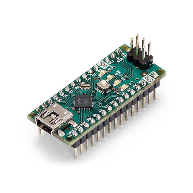
Arduino Arduino Nano
The Arduino Nano is a small, complete, and breadboard-friendly board based on the ATmega328 (Arduino Nano 3.x). It has more or less the same functionality of the Arduino Duemilanove but in a different package. It lacks only a DC power jack and works with a Mini-B USB cable instead of a standard one. Specifications Microcontroller ATmega328 Operating Voltage (logic level) 5 V Input Voltage (recommended) 7-12 V Input Voltage (limits) 6-20 V Digital I/O Pins 14 (of which 6 provide PWM output) Analog Input Pins 8 DC Current per I/O Pin 40 mA Flash Memory 16 KB (ATmega168) or 32 KB (ATmega328) of which 2 KB used by bootloader SRAM 1 KB (ATmega168) or 2 KB (ATmega328) EEPROM 512 bytes (ATmega168) or 1 KB (ATmega328) Clock Speed 16 MHz Dimensions 0.73 x 1.70' (18 x 45 mm) Power The Arduino Nano can be powered via the Mini-B USB connection, 6-20 V unregulated external power supply (pin 30), or 5 V regulated external power supply (pin 27). The power source is automatically selected to the highest voltage source. Memory The ATmega168 has 16 KB of flash memory for storing code (of which 2 KB is used for the bootloader), 1 KB of SRAM and 512 bytes of EEPROM The ATmega328 has 32 KB of flash memory for storing code, (also with 2 KB used for the bootloader), 2 KB of SRAM and 1 KB of EEPROM. Input and Output Each of the 14 digital pins on the Nano can be used as an input or output, using pinMode(), digitalWrite(), and digitalRead() functions. They operate at 5 V. Each pin can provide or receive a maximum of 40 mA and has an internal pull-up resistor (disconnected by default) of 20-50 kOhms. Communication The Arduino Nano has a number of facilities for communicating with a computer, another Arduino, or other microcontrollers. The ATmega168 and ATmega328 provide UART TTL (5V) serial communication, which is available on digital pins 0 (RX) and 1 (TX). An FTDI FT232RL on the board channels this serial communication over USB and the FTDI drivers (included with the Arduino software) provide a virtual com port to software on the computer. The Arduino software includes a serial monitor which allows simple textual data to be sent to and from the Arduino board. The RX and TX LEDs on the board will flash when data is being transmitted via the FTDI chip and USB connection to the computer (but not for serial communication on pins 0 and 1). A SoftwareSerial library allows for serial communication on any of the Nano's digital pins. Programming The Arduino Nano can be programmed with the Arduino software (download). The ATmega168 or ATmega328 on the Arduino Nano comes with a bootloader that allows you to upload new code to it without the use of an external hardware programmer. It communicates using the original STK500 protocol (reference, C header files). You can also bypass the bootloader and program the microcontroller through the ICSP (In-Circuit Serial Programming) header using Arduino ISP or similar; see these instructions for details. Automatic (Software) Reset Rather than requiring a physical press of the reset button before an upload, the Arduino Nano is designed in a way that allows it to be reset by software running on a connected computer. One of the hardware flow control lines (DTR) of theFT232RL is connected to the reset line of the ATmega168 or ATmega328 via a 100 nF capacitor. When this line is asserted (taken low), the reset line drops long enough to reset the chip. The Arduino software uses this capability to allow you to upload code by simply pressing the upload button in the Arduino environment. This means that the bootloader can have a shorter timeout, as the lowering of DTR can be well-coordinated with the start of the upload.
€ 22,95
Members € 20,66
-

Elektor Digital Arduino & Co – Measure, Control, and Hack (E-book)
Clever Tricks with ATmega328 Pro Mini Boards With a simple Pro Mini board and a few other components, projects that 20 or 30 years ago were unthinkable (or would have cost a small fortune) are realized easily and affordably in this book: From simple LED effects to a full battery charging and testing station that will put a rechargeable through its paces, there’s something for everyone. All the projects are based on the ATmega328 microcontroller, which offers endless measuring, switching, and control options with its 20 input and output lines. For example, with a 7-segment display and a few resistors, you can build a voltmeter or an NTC-based thermometer. The Arduino platform offers the perfect development environment for programming this range of boards. Besides these very practical projects, the book also provides the necessary knowledge for you to create projects based on your own ideas. How to measure, and what? Which transistor is suitable for switching a certain load? When is it better to use an IC? How do you switch mains voltage? Even LilyPad-based battery-operated projects are discussed in detail, as well as many different motors, from simple DC motors to stepper motors. Sensors are another exciting topic: For example, a simple infrared receiver that can give disused remote controls a new lease on life controlling your home, and a tiny component that can actually measure the difference in air pressure between floor and table height!
€ 32,95
Members € 26,36
-
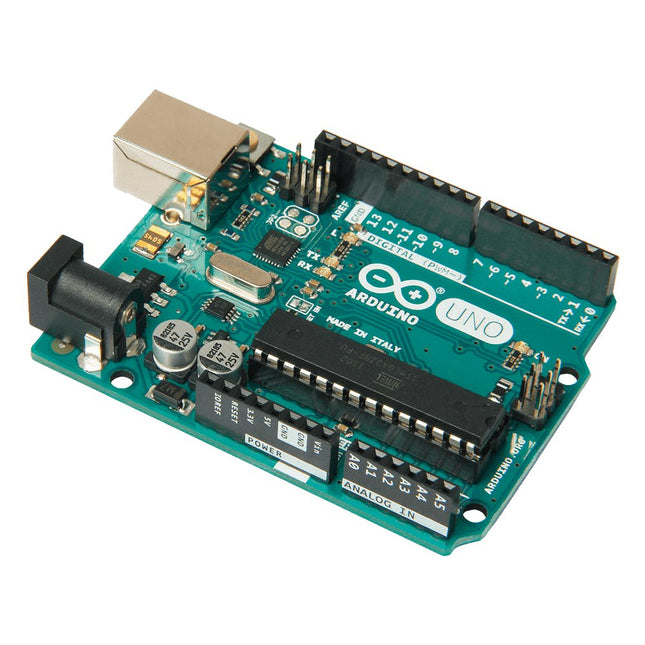
Arduino Arduino Uno Rev3
Arduino Uno is an open-source microcontroller board based on the ATmega328P. It has 14 digital input/output pins (of which 6 can be used as PWM outputs), 6 analog inputs, a 16 MHz ceramic resonator (CSTCE16M0V53-R0), a USB connection, a power jack, an ICSP header and a reset button. It contains everything needed to support the microcontroller; simply connect it to a computer with a USB cable or power it with a AC-to-DC adapter or battery to get started. You can tinker with your Uno without worring too much about doing something wrong, worst case scenario you can replace the chip for a few dollars and start over again. 'Uno' means one in Italian and was chosen to mark the release of Arduino Software (IDE) 1.0. The Uno board and version 1.0 of Arduino Software (IDE) were the reference versions of Arduino, now evolved to newer releases. The Uno board is the first in a series of USB Arduino boards, and the reference model for the Arduino platform; for an extensive list of current, past or outdated boards see the Arduino index of boards. Specifications Microcontroller ATmega328P Operating Voltage 5 V Input Voltage (recommended) 7-12 V Input Voltage (limit) 6-20 V Digital I/O Pins 14 (of which 6 provide PWM output) PWM Digital I/O Pins 6 Analog Input Pins 6 DC Current per I/O Pin 20 mA DC Current for 3.3 V Pin 50 mA Flash Memory 32 KB (ATmega328P) of which 0.5 KB used by bootloader SRAM 2 KB (ATmega328P) EEPROM 1 KB (ATmega328P) Clock Speed 16 MHz LED_BUILTIN 13 Dimensions 68.6 x 53.4 mm Weight 25 g
€ 24,95
Members identical
-
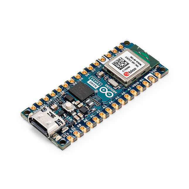
Arduino Arduino Nano ESP32
The Arduino Nano ESP32 (with and without headers) is a Nano form factor board based on the ESP32-S3 (embedded in the NORA-W106-10B from u-blox). This is the first Arduino board to be based fully on an ESP32, and features Wi-Fi, Bluetooth LE, debugging via native USB in the Arduino IDE as well as low power. The Nano ESP32 is compatible with the Arduino IoT Cloud, and has support for MicroPython. It is an ideal board for getting started with IoT development. Features Tiny footprint: Designed with the well-known Nano form factor in mind, this board's compact size makes it perfect for embedding in standalone projects. Wi-Fi and Bluetooth: Harness the power of the ESP32-S3 microcontroller, well-known in the IoT realm, with full Arduino support for wireless and Bluetooth connectivity. Arduino and MicroPython support: Seamlessly switch between Arduino and MicroPython programming with a few simple steps. Arduino IoT Cloud compatible: Quickly and easily create IoT projects with just a few lines of code. The setup takes care of security, allowing you to monitor and control your project from anywhere using the Arduino IoT Cloud app. HID support: Simulate human interface devices, such as keyboards or mice, over USB, opening up new possibilities for interacting with your computer. Specifications Microcontroller u-blox NORA-W106 (ESP32-S3) USB connector USB-C Pins Built-in LED pins 13 Built-in RGB LED pins 14-16 Digital I/O pins 14 Analog input pins 8 PWM pins 5 External interrupts All digital pins Connectivity Wi-Fi u-blox NORA-W106 (ESP32-S3) Bluetooth u-blox NORA-W106 (ESP32-S3) Communication UART 2x I²C 1x, A4 (SDA), A5 (SCL) SPI D11 (COPI), D12 (CIPO), D13 (SCK). Use any GPIO for Chip Select (CS) Power I/O Voltage 3.3 V Input voltage (nominal) 6-21 V Source Current per I/O pin 40 mA Sink Current per I/O pin 28 mA Clock speed Processor Up to 240 MHz Memory ROM 384 kB SRAM 512 kB External Flash 128 Mbit (16 MB) Dimensions 18 x 45 mm Downloads Datasheet Schematics
€ 23,95€ 17,95
Members identical
-
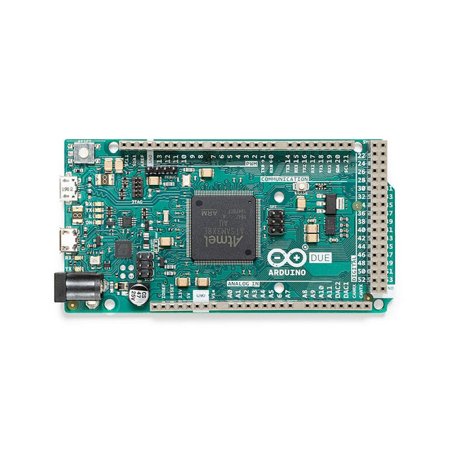
Arduino Arduino Due with Headers
The board contains everything needed to support the microcontroller; simply connect it to a computer with a micro-USB cable or power it with an AC-to-DC adapter or battery to get started. The Due is compatible with all Arduino shields that work at 3.3V and are compliant with the 1.0 Arduino pinout. The Due follows the 1.0 pinout: TWI: SDA and SCL pins that are near to the AREF pin. IOREF: allows an attached shield with the proper configuration to adapt to the voltage provided by the board. This enables shield compatibility with a 3.3V board like the Due and AVR-based boards which operate at 5V. An unconnected pin, reserved for future use. Specifications Operating Voltage 3.3 V Input Voltage 7-12 V Digital I/O 54 Analog Input Pins 12 Analog Output Pins 2 (DAC) Total DC Output Current on all I/O Lines 130 mA DC Current per I/O Pin 20 mA DC Current for 3.3 V Pin 800 mA DC Current for 5 V Pin 800 mA Flash Memory 512 KB all available for the user applications SRAM 96 KB Clock Speed 84 MHz Length 101.52 mm Width 53.3 mm Weight 36 g Please note: Unlike most Arduino boards, the Arduino Due board runs at 3.3V. The maximum voltage that the I/O pins can tolerate is 3.3V. Applying voltages higher than 3.3V to any I/O pin could damage the board.
€ 44,95
Members € 40,46
-
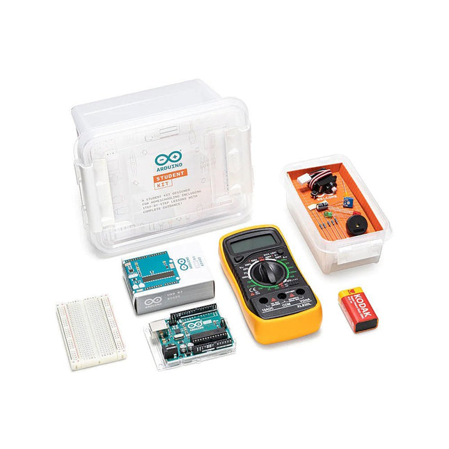
Arduino Arduino Student Kit
The Arduino Student Kit is a hands-on, step-by-step remote learning tool for ages 11+: get started with the basics of electronics, programming, and coding at home. No prior knowledge or experience is necessary as the kit guides you through step by step. Educators can teach their class remotely using the kits, and parents can use the kit as a homeschool tool for their child to learn at their own pace. Everyone will gain confidence in programming and electronics with guided lessons and open experimentation. Learn the basics of programming, coding and electronics including current, voltage, and digital logic. No prior knowledge or experience is necessary as the kit guides you through step by step. You’ll get all the hardware and software you need for one person, making it ideal to use for remote teaching, homeschooling, and for self-learning. There are step-by-step lessons, exercises, and for a complete and in-depth experience, there’s also extra content including invention spotlights, concepts, and interesting facts about electronics, technology, and programming. Lessons and projects can be paced according to individual abilities, allowing them to learn from home at their own level. The kit can also be integrated into different subjects such as physics, chemistry, and even history. In fact, there’s enough content for an entire semester. How educators can use the kit for remote teaching The online platform contains all the content you need to teach remotely: exclusive learning guidance content, tips for remote learning, nine 90-minute lessons, and two open-ended projects. Each lesson builds off the previous one, providing a further opportunity to apply the skills and concepts students have already learned. They also get a logbook to complete as they work through the lessons. The beginning of each lesson provides an overview, estimated completion times, and learning objectives. Throughout each lesson, there are tips and information that will help to make the learning experience easier. Key answers and extension ideas are also provided. How the kit helps parents homeschool their children This is your hands-on, step-by-step remote learning tool that will help your child learn the basics of programming, coding, and electronics at home. As a parent, you don’t need any prior knowledge or experience as you are guided through step-by-step. The kit is linked directly into the curriculum so you can be confident that your children are learning what they should be, and it provides the opportunity for them to become confident in programming and electronics. You’ll also be helping them learn vital skills such as critical thinking and problem-solving. Self-learning with the Arduino Student Kit Students can use this kit to teach themselves the basics of electronics, programming, and coding. As all the lessons follow step-by-step instructions, it’s easy for them to work their way through and learn on their own. They can work at their own pace, have fun with all the real-world projects, and increase their confidence as they go. They don’t need any previous knowledge as everything is clearly explained, coding is pre-written, and there’s a vocabulary of concepts to refer to. The Arduino Student Kit comes with several parts and components that will be used to build circuits while completing the lessons and projects throughout the course. Included in the kit Access code to exclusive online content including learning guidance notes, step-by-step lessons and extra materials such as resources, invention spotlights and a digital logbook with solutions. 1x Arduino Uno 1x USB cable 1x Board mounting base 1x Multimeter 1x 9 V battery snap 1x 9 V battery 20x LEDs (5x red, 5x green, 5x yellow & 5x blue ) 5x Resistors 560 Ω 5x Resistors 220 Ω 1x Breadboard 400 points 1x Resistor 1 kΩ 1x Resistor 10 kΩ 1x Small Servo motor 2x Potentiometers 10 kΩ 2x Knob potentiometers 2x Capacitors 100 uF Solid core jumper wires 5x Pushbuttons 1x Phototransistor 2x Resistors 4.7 kΩ 1x Jumper wire black 1x Jumper wire red 1x Temperature sensor 1x Piezo 1x Jumper wire female to male red 1x Jumper wire female to male black 3x Nuts and Bolts
€ 79,95€ 59,95
Members identical
-

Arduino Arduino MKR Zero
The Arduino MKR Zero is a development board for music makers! With an SD card holder and dedicated SPI interfaces (SPI1), you are able to play music files without extra hardware. The MKR Zero brings you the power of a Zero in the smaller format established by the MKR form factor. The MKR Zero board acts as a great educational tool for learning about 32-bit application development. It has an on-board SD connector with dedicated SPI interfaces (SPI1) that allows you to play with MUSIC files with no extra hardware! The board is powered by Atmel’s SAMD21 MCU, which features a 32-bit ARM Cortex M0+ core. The board contains everything needed to support the microcontroller; simply connect it to a computer with a micro-USB cable or power it by a LiPo battery. The battery voltage can also be monitored since a connection between the battery and the analog converter of the board exists. Specifications Microcontroller SAMD21 ARM Cortex-M0+ 32-bit low power Board power supply (USB/VIN) 5 V Supported battery Li-Po single cell, 3.7 V, 700 mAh minimum DC current for 3.3 V pin 600 mA DC current for 5 V pin 600 mA Circuit operating voltage 3.3 V Digital I/O pins 22 PWM pins 12 (0, 1, 2, 3, 4, 5, 6, 7, 8, 10, A3 - or 18 -, A4 -or 19) UART 1 SPI 1 I²C 1 Analog input pins 7 (ADC 8/10/12 bit) Analog output pins 1 (DAC 10 bit) External interrupts 10 (0, 1, 4, 5, 6, 7, 8, A1 -or 16-, A2 - or 17) DC current per I/O pin 7 mA Flash memory 256 KB Flash memory for bootloader 8 KB SRAM 32 KB EEPROM No Clock speed 32.768 kHz (RTC), 48 MHz LED_BUILTIN 32 Downloads Datasheet Eagle Files Schematics Fritzing Pinout
€ 36,95
Members € 33,26
-
Arduino Arduino Portenta HAT Carrier
Portenta HAT Carrier is a reliable and robust carrier that transforms Portenta X8 into an industrial single board computer compatible with Raspberry Pi HATs and cameras. It is ideal for multiple industrial applications such as building automation and machine monitoring. Compatible also with Portenta H7 and Portenta C33, Portenta HAT Carrier provides easy access to multiple peripherals – including CAN, Ethernet, microSD and USB – and further extends any Portenta application. It is great for prototyping and ready for scaling up, it extends the features found on a typical Raspberry Pi Model B. Debug quickly with dedicated JTAG pins and keeps heat manageable under intense workloads with a PWM fan connector. Control actuators or read analog sensors via the additional 16x analog I/Os. Add industrial machine vision solutions to any project by leveraging the onboard camera connector. Features Add Raspberry Pi HATs to your Portenta projects Quickly access CAN, USB, and Ethernet peripherals Leverage onboard MicroSD card to log data Enjoy simple debugging through the onboard JTAG pins Easily control actuators and read sensors via 16x analog I/Os Leveraging the onboard camera connector for machine vision Portenta takes you from prototype to high-performance Portenta HAT Carrier offers you a frictionless Linux prototyping experience and unlocks the ability for integrated real-time MCU solutions. Portenta HAT Carrier extends Portenta SOMs for faster, easier and more efficient testing for your ideas while also ensuring the capabilities and industrial-grade performances the Portenta range is known for. Extend the Raspberry Pi ecosystem for commercial applications Combine the ease of use, accessibility and incredible support from both the Arduino and Raspberry Pi communities for your next project with the carrier designed to combine and extend MPU and MCU applications for the development of advanced commercial solutions. Specifications Connectors High-density connectors compatible with Portenta products 1x USB-A female connector 1x Gigabit Ethernet connector (RJ45) 1x CAN FD with onboard transceiver 1x MIPI Camera connector 1x MicroSD card slot 1x PWM fan connector 40-pin header connector allowing compatibility with Raspberry Pi HATs 16-pin analog header connectors, including: 8x analog inputs 1x GPIO 1xUART without flow control 2x PWM pins 1x LICELL pin for Portenta's RTC power Interfaces CAN FD UART SAI ANALOG GPIO SPI I²C I²S PWM Debugging Onboard 10x pin 1.27 mm JTAG connector Power From onboard screw terminal block allowing: 7-32 V power supply, powering both the carrier and the connected Portenta 5 V power supply From USB-C on Portenta From 5 V on 40-pin header connector Dimensions 85 x 56 mm Downloads Datasheet Schematics
€ 54,95€ 39,95
Members identical
-
Arduino Arduino MKR WAN 1310
Ever wanted an automated house? Or a smart garden? Well, now it’s easy with the Arduino IoT Cloud compatible boards. It means: you can connect devices, visualize data, control and share your projects from anywhere in the world. Whether you’re a beginner or a pro, we have a wide range of plans to make sure you get the features you need. Connect your sensors and actuators over long distances harnessing the power of the LoRa wireless protocol or throughout LoRaWAN networks. The Arduino MKR WAN 1310 board provides a practical and cost effective solution to add LoRa connectivity to projects requiring low power. This open source board can be connected to the Arduino IoT Cloud. Better and More Efficient The MKR WAN 1310, brings in a series of improvements when compared to its predecessor, the MKR WAN 1300. While still based on the Microchip SAMD21 low power processor, the Murata CMWX1ZZABZ LoRa module, and the MKR family’s characteristic crypto chip (the ECC508), the MKR WAN 1310 includes a new battery charger, a 2 MByte SPI Flash, and improved control of the board’s power consumption. Improved Battery Power The latest modifications have considerably improved the battery life on the MKR WAN 1310. When properly configured, the power consumption is now as low as 104 uA! It is also possible to use the USB port to supply power (5 V) to the board; run the board with or without batteries – the choice is yours. On-board Storage Data logging and other OTA (Over The Air) functions are now possible since the inclusion of the on board 2 MByte Flash. This new exciting feature will let you transfer configuration files from the infrastructure onto the board, create your own scripting commands, or simply store data locally to send it whenever the connectivity is best. Whilst the MKR WAN 1310’s crypto chip adds further security by storing credentials & certificates in the embedded secure element. These features make it the perfect IoT node and building block for low-power wide-area IoT devices. Specifications The Arduino MKR WAN 1310 is based on the SAMD21 microcontroller. Microcontroller SAMD21 Cortex-M0+ 32-bit low power ARM MCU (datasheet) Radio module CMWX1ZZABZ (datasheet) Board power supply (USB/VIN) 5 V Secure element ATECC508 (datasheet) Supported batteries Rechargeable Li-Ion, or Li-Po, 1024 mAh minimum capacity Circuit operating voltage 3.3 V Digital I/O pins 8 PWM pins 13 (0 .. 8, 10, 12, 18 / A3, 19 / A4) UART 1 SPI 1 I²C 1 Analog input pins 7 (ADC 8/10/12 bit) Analog output pins 1 (DAC 10 bit) External interrupts 8 (0, 1, 4, 5, 6, 7, 8, 16 / A1, 17 / A2) DC current per I/O pin 7 mA CPU flash memory 256 KB (internal) QSPI flash memory 2 MByte (external) SRAM 32 KB EEPROM No Clock speed 32.768 kHz (RTC), 48 MHz LED_BUILTIN 6 USB Full-Speed USB Device and embedded Host Antenna gain 2 dB (bundled pentaband antenna) Carrier frequency 433/868/915 MHz Dimensions 67.64 x 25 mm Weight 32 g Downloads Eagle Files Schematics Fritzing Pinout
€ 59,95
Members € 53,96
-
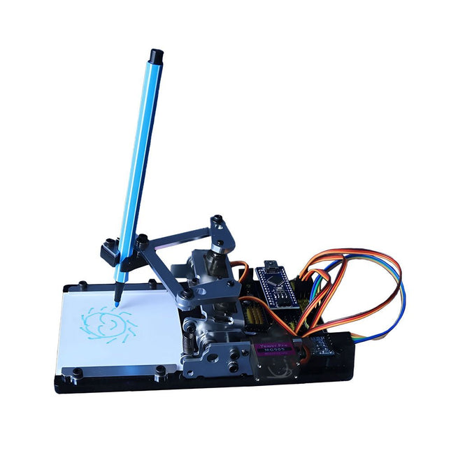
Generic Arduino-controlled Drawing Robot
This versatile plotter robot arm DIY kit for Arduino is equipped with MG90S metal gear servo motors to ensure precise and stable drawing movements. Features Fully compatible with Arduino IDE, includes complete source code for easy development and customization. Equipped with robust MG90S metal gear servo motors for accuracy and durability. Includes a Bluetooth module enabling wireless operation via a dedicated app. Specially designed robotic arm tip securely holds pens or markers with a diameter of 8-10 mm, ideal for sketches and detailed drawings. Included Arduino-compatible Nano motherboard Nano expansion board Bluetooth module MG90S all-metal gear servo motors Aluminum structural frame Thickened stable base plate Screw and fastening accessories Connecting wires USB data cable
€ 64,95€ 44,95
Members identical
-
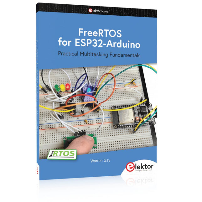
Elektor Publishing FreeRTOS for ESP32-Arduino
Practical Multitasking Fundamentals Programming embedded systems is difficult because of resource constraints and limited debugging facilities. Why develop your own Real-Time Operating System (RTOS) as well as your application when the proven FreeRTOS software is freely available? Why not start with a validated foundation? Every software developer knows that you must divide a difficult problem into smaller ones to conquer it. Using separate preemptive tasks and FreeRTOS communication mechanisms, a clean separation of functions is achieved within the entire application. This results in safe and maintainable designs. Practicing engineers and students alike can use this book and the ESP32 Arduino environment to wade into FreeRTOS concepts at a comfortable pace. The well-organized text enables you to master each concept before starting the next chapter. Practical breadboard experiments and schematics are included to bring the lessons home. Experience is the best teacher. Each chapter includes exercises to test your knowledge. The coverage of the FreeRTOS Application Programming Interface (API) is complete for the ESP32 Arduino environment. You can apply what you learn to other FreeRTOS environments, including Espressif’s ESP-IDF. The source code is available from GitHub. All of these resources put you in the driver’s seat when it is time to develop your next uber-cool ESP32 project. What you will learn: How preemptive scheduling works within FreeRTOS The Arduino startup “loopTask” Message queues FreeRTOS timers and the IDLE task The semaphore, mutex, and their differences The mailbox and its application Real-time task priorities and its effect Interrupt interaction and use with FreeRTOS Queue sets Notifying tasks with events Event groups Critical sections Task local storage The gatekeeper task
€ 44,95
Members € 40,46


