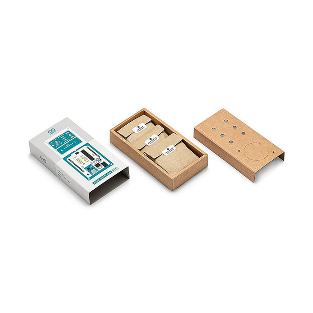
Learn the basics of electronics by assembling manually your Arduino Uno, become familiar with soldering by mounting every single component, and then unleash your creativity with the only kit that becomes a synth!
The Arduino Make-Your-Uno kit is really the best way to learn how to solder. And when you are done, the packaging allows you to build a synth and make your music.
A kit with all the components to build your very own Arduino Uno and audio synthesizer shield.
The Make-Your-Uno kit comes with a complete set of instructions in a dedicated content platform. This includes video material, a 3D interactive viewer for following detailed instructions, and how to program your board once it is finished.
This kit contains:
Arduino Make-Your-Uno
1x Make-Your-Uno PCB
1x USB C Serial adapter Board
7x Resistors 1k Ohm
2x Resistors 10k Ohm
2x Resistors 1M Ohm
1x Diode (1N4007)
1x 16 MHz Crystal
4x Yellow LEDs
1x Green LED
1x Push-Button
1x MOSFET
1x LDO (3.3 V)
1x LDO (5 V)
3x Ceramic capacitors (22pF)
3x Electrolytic capacitors (47uF)
7x Polyester capacitors (100nF)
1x Socket for ATMega 328p
2x I/O Connectors
1x Connector header 6 pins
1x Barrel jack connector
1x ATmega 328p Microcontroller
Arduino Audio Synth
1x Audio Synth PCB
1x Resistor 100k Ohm
1x Resistor 10 Ohm
1x Audio amplifier (LM386)
1x Ceramic capacitors (47nF)
1x Electrolytic capacitors (47uF)
1x Electrolytic capacitors (220uF)
1x Polyester capacitor (100nF)
4x connectors pin header
6x potentiometer 10k Ohm with plastic knobs
Spare parts
2x Electrolytic capacitors (47uF)
2x Polyester capacitor (100nF)
2x Ceramic capacitors (22pF)
1x Push-Button
1x Yellow LEDs
1x Green LED
Mechanical parts
5x Spacers 12 mm
11x Spacers 6 mm
5x screw nuts
2x screws 12 mm
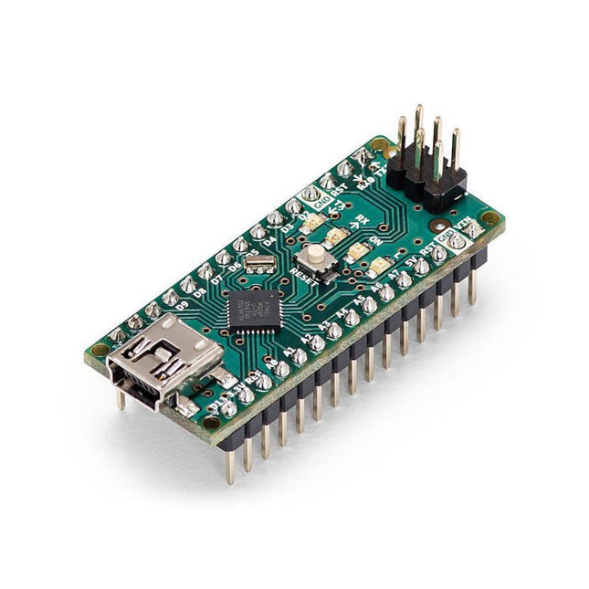
The Arduino Nano is a small, complete, and breadboard-friendly board based on the ATmega328 (Arduino Nano 3.x). It has more or less the same functionality of the Arduino Duemilanove but in a different package. It lacks only a DC power jack and works with a Mini-B USB cable instead of a standard one.
Specifications
Microcontroller
ATmega328
Operating Voltage (logic level)
5 V
Input Voltage (recommended)
7-12 V
Input Voltage (limits)
6-20 V
Digital I/O Pins
14 (of which 6 provide PWM output)
Analog Input Pins
8
DC Current per I/O Pin
40 mA
Flash Memory
16 KB (ATmega168) or 32 KB (ATmega328) of which 2 KB used by bootloader
SRAM
1 KB (ATmega168) or 2 KB (ATmega328)
EEPROM
512 bytes (ATmega168) or 1 KB (ATmega328)
Clock Speed
16 MHz
Dimensions
0.73 x 1.70' (18 x 45 mm)
Power
The Arduino Nano can be powered via the Mini-B USB connection, 6-20 V unregulated external power supply (pin 30), or 5 V regulated external power supply (pin 27). The power source is automatically selected to the highest voltage source.
Memory
The ATmega168 has 16 KB of flash memory for storing code (of which 2 KB is used for the bootloader), 1 KB of SRAM and 512 bytes of EEPROM
The ATmega328 has 32 KB of flash memory for storing code, (also with 2 KB used for the bootloader), 2 KB of SRAM and 1 KB of EEPROM.
Input and Output
Each of the 14 digital pins on the Nano can be used as an input or output, using pinMode(), digitalWrite(), and digitalRead() functions. They operate at 5 V.
Each pin can provide or receive a maximum of 40 mA and has an internal pull-up resistor (disconnected by default) of 20-50 kOhms.
Communication
The Arduino Nano has a number of facilities for communicating with a computer, another Arduino, or other microcontrollers.
The ATmega168 and ATmega328 provide UART TTL (5V) serial communication, which is available on digital pins 0 (RX) and 1 (TX). An FTDI FT232RL on the board channels this serial communication over USB and the FTDI drivers (included with the Arduino software) provide a virtual com port to software on the computer.
The Arduino software includes a serial monitor which allows simple textual data to be sent to and from the Arduino board. The RX and TX LEDs on the board will flash when data is being transmitted via the FTDI chip and USB connection to the computer (but not for serial communication on pins 0 and 1).
A SoftwareSerial library allows for serial communication on any of the Nano's digital pins.
Programming
The Arduino Nano can be programmed with the Arduino software (download).
The ATmega168 or ATmega328 on the Arduino Nano comes with a bootloader that allows you to upload new code to it without the use of an external hardware programmer. It communicates using the original STK500 protocol (reference, C header files).
You can also bypass the bootloader and program the microcontroller through the ICSP (In-Circuit Serial Programming) header using Arduino ISP or similar; see these instructions for details.
Automatic (Software) Reset
Rather than requiring a physical press of the reset button before an upload, the Arduino Nano is designed in a way that allows it to be reset by software running on a connected computer.
One of the hardware flow control lines (DTR) of theFT232RL is connected to the reset line of the ATmega168 or ATmega328 via a 100 nF capacitor. When this line is asserted (taken low), the reset line drops long enough to reset the chip.
The Arduino software uses this capability to allow you to upload code by simply pressing the upload button in the Arduino environment. This means that the bootloader can have a shorter timeout, as the lowering of DTR can be well-coordinated with the start of the upload.
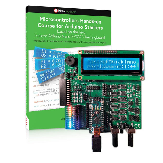
Realize your own projects with the Elektor Arduino Nano MCCAB Training Board
The microcontroller is probably the most fascinating subfield of electronics. Due to the multitude of functions, it combines on its chip, it is a universal multi-tool for developers to realize their projects. Practically every device of daily use today is controlled by a microcontroller. However, for an electronic layman, realizing his own ideas with a microcontroller has so far remained a pipe dream due to its complexity. The Arduino concept has largely simplified the use of microcontrollers, so that now even laymen can realize their own electronics ideas with a microcontroller.
Book & Hardware in the Bundle: 'Learning by Doing'
This book, which is included in the bundle, shows how you can realize your own projects with a microcontroller even without much experience in electronics and programming languages. It is a microcontrollers hands-on course for starters, because after an overview of the internals of the microcontroller and an introduction to the programming language C, the focus of the course is on the practical exercises. The reader acquires the necessary knowledge by 'learning by doing': in the extensive practical section with 12 projects and 46 exercises, what is learned in the front part of the book is underpinned with many examples. The exercises are structured in such a way that the user is given a task to solve using the knowledge built up in the theoretical part of the book. Each exercise is followed by a sample solution that is explained and commented on in detail, which helps the user to solve problems and compare it with his own solution.
Arduino IDE
The Arduino IDE is a software development environment that can be downloaded for free to your own PC and that contains the entire software package needed for your own microcontroller projects. You write your programs ('apps') with the IDE’s editor in the C programming language. You translate them into the bits and bytes that the microcontroller understands using the Arduino IDE's built-in compiler, and then load them into the microcontroller's memory on the Elektor Arduino MCCAB Nano Training Board via a USB cable.
Query or control external sensors, motors or assemblies
In addition to an Arduino Nano microcontroller module, the Elektor Arduino Nano MCCAB Training Board contains all the components required for the exercises, such as light-emitting diodes, switches, pushbuttons, acoustic signal transmitters, etc. External sensors, motors or assemblies can also be queried or controlled with this microcontroller training system.
Specifications (Arduino Nano MCCAB Training Board)
Power Supply
Via the USB connection of the connected PC or an external power supply unit (not included)
Operating Voltage
+5 Vcc
Input Voltage
All inputs
0 V to +5 V
VX1 and VX2
+8 V to +12 V (only when using an external power supply)
Hardware periphery
LCD
2x16 characters
Potentiometer P1 & P2
JP3: selection of operating voltage of P1 & P2
Distributor
SV4: Distributor for the operating voltagesSV5, SV6: Distributor for the inputs/outputs of the microcontroller
Switches and buttons
RESET button on the Arduino Nano module 6x pushbutton switches K1 ... K6 6x slide switches S1 ... S6 JP2: Connection of the switches with the inputs of the microcontroller
Buzzer
Piezo buzzer Buzzer1 with jumper on JP6
Indicator lights
11 x LED: Status indicator for the inputs/outputs LED L on the Arduino Nano module, connected to GPIO D13 JP6: Connection of LEDs LD10 ... LD20 with GPIOs D2 ... D12
Serial interfacesSPI & I²C
JP4: Selection of the signal at pin X of the SPI connector SV12 SV9 to SV12: SPI interface (3.3 V/5 V) or I²C interface
Switching output for external devices
SV1, SV7: Switching output (maximum +24 V/160 mA, externally supplied) SV2: 2x13 pins for connection of external modules
3x3 LED matrix(9 red LEDs)
SV3: Columns of the 3x3 LED matrix (outputs D6 ... D8) JP1: Connection of the rows with the GPIOs D3 ... D5
Software
Library MCCABLib
Control of hardware components (switches, buttons, LEDs, 3x3 LED matrix, buzzer) on the MCCAB Training Board
Operating Temperature
Up to +40 °C
Dimensions
100 x 100 x 20 mm
Specifications (Arduino Nano)
Microcontroller
ATmega328P
Architecture
AVR
Operating Voltage
5 V
Flash Memory
32 KB, of which 2 KB used by bootloader
SRAM
2 KB
Clock Speed
16 MHz
Analog IN Pins
8
EEPROM
1 KB
DC Current per I/O Pins
40 mA on one I/O pin, total maximum 200 mA on all pins together
Input Voltage
7-12 V
Digital I/O Pins
22 (6 of which are PWM)
PWM Output
6
Power Consumption
19 mA
Dimensions
18 x 45 mm
Weight
7 g
Included
1x Elektor Arduino Nano MCCAB Training Board
1x Arduino Nano
1x Book: Microcontrollers Hands-on Course for Arduino Starters
The Elektor MultiCalculator Kit is an Arduino-based multifunction calculator that goes beyond basic calculations. It offers 22 functions including light and temperature measurement, differential temperature analysis, and NEC IR remote control decoding. The Elektor MultiCalculator is a handy tool for use in your projects or for educational purposes.
The kit features a Pro Mini module as the computing unit. The PCB is easy to assemble using through-hole components. The enclosure consists of 11 acrylic panels and mounting materials for easy assembly. Additionally, the device is equipped with a 16x2 alphanumeric LCD, 20 buttons, and temperature sensors.
The Elektor MultiCalculator is programmable with the Arduino IDE through a 6-way PCB header. The available software is bilingual (English and Dutch). The calculator can be programmed with a programming adapter, and it is powered through USB-C.
Modes of Operation
Calculator
4-Ring Resistor Code
5-Ring Resistor Code
Decimal to Hexadecimal and Character (ASCII) conversion
Hexadecimal to Decimal and Character (ASCII) conversion
Decimal to Binary and Character (ASCII) conversion
Binary to Decimal and Hexadecimal conversion
Hz, nF, capacitive reactance (XC) calculation
Hz, µH, inductive reactance (XL) calculation
Resistance calculation of two resistors connected in parallel
Resistance calculation of two resistors connected in series
Calculation of unknown parallel resistor
Temperature measurement
Differential temperature measurement T1&T2 and Delta (δ)
Light measurement
Stopwatch with lap time function
Item counter
NEC IR remote control decoding
AWG conversion (American Wire Gauge)
Rolling Dice
Personalize startup message
Temperature calibration
Specifications
Menu languages: English, Dutch
Dimensions: 92 x 138 x 40 mm
Build time: approx. 5 hours
Included
PCB and though-hole components
Precut acrylic sheets with all mechanical parts
Pro Mini microcontroller module (ATmega328/5 V/16 MHz)
Programming adapter
Waterproof temperature sensors
USB-C cable
Downloads
Software
The Arduino MKR Zero is a development board for music makers! With an SD card holder and dedicated SPI interfaces (SPI1), you are able to play music files without extra hardware.
The MKR Zero brings you the power of a Zero in the smaller format established by the MKR form factor. The MKR Zero board acts as a great educational tool for learning about 32-bit application development. It has an on-board SD connector with dedicated SPI interfaces (SPI1) that allows you to play with MUSIC files with no extra hardware! The board is powered by Atmel’s SAMD21 MCU, which features a 32-bit ARM Cortex M0+ core.
The board contains everything needed to support the microcontroller; simply connect it to a computer with a micro-USB cable or power it by a LiPo battery. The battery voltage can also be monitored since a connection between the battery and the analog converter of the board exists.
Specifications
Microcontroller
SAMD21 ARM Cortex-M0+ 32-bit low power
Board power supply (USB/VIN)
5 V
Supported battery
Li-Po single cell, 3.7 V, 700 mAh minimum
DC current for 3.3 V pin
600 mA
DC current for 5 V pin
600 mA
Circuit operating voltage
3.3 V
Digital I/O pins
22
PWM pins
12 (0, 1, 2, 3, 4, 5, 6, 7, 8, 10, A3 - or 18 -, A4 -or 19)
UART
1
SPI
1
I²C
1
Analog input pins
7 (ADC 8/10/12 bit)
Analog output pins
1 (DAC 10 bit)
External interrupts
10 (0, 1, 4, 5, 6, 7, 8, A1 -or 16-, A2 - or 17)
DC current per I/O pin
7 mA
Flash memory
256 KB
Flash memory for bootloader
8 KB
SRAM
32 KB
EEPROM
No
Clock speed
32.768 kHz (RTC), 48 MHz
LED_BUILTIN
32
Downloads
Datasheet
Eagle Files
Schematics
Fritzing
Pinout
Arduino MKR NB 1500 allows you to build your next smart project.
Ever wanted an automated house? Or a smart garden? Well, now it’s easy with the Arduino IoT Cloud compatible boards. It means: you can connect devices, visualize data, control and share your projects from anywhere in the world. Whether you’re a beginner or a pro, we have a wide range of plans to make sure you get the features you need.
Add Narrowband communication to your project with the MKR NB 1500. It's the perfect choice for devices in remote locations without an Internet connection, or in situations in which power isn't available like on-field deployments, remote metering systems, solar-powered devices, or other extreme scenarios.
The board's main processor is a low power ARM Cortex-M0 32-bit SAMD21, like in the other boards within the Arduino MKR family. The Narrowband connectivity is performed with a module from u-blox, the SARA-R410M-02B, a low power chipset operating in the de different bands of the IoT LTE cellular range. On top of those, secure communication is ensured through the Microchip ECC508 crypto chip. Besides that, the pcb includes a battery charger, and a connector for an external antenna.
This board is designed for global use, providing connectivity on LTE's Cat M1/NB1 bands 1, 2, 3, 4, 5, 8, 12, 13, 18, 19, 20, 25, 26, 28. Operators offering service in that part of the spectrum include: Vodafone, AT&T, T-Mobile USA, Telstra, and Verizon, among others.
Specifications
The Arduino MKR NB 1500 is based on the SAMD21 microcontroller.
Microcontroller
SAMD21 Cortex-M0+ 32-bit low power ARM MCU (datasheet)
Radio module
u-blox SARA-R410M-02B (datasheet summary)
Secure element
ATECC508 (datasheet)
Board power supply (USB/VIN)
5 V
Supported battery
Li-Po Single Cell, 3.7 V, 1500 mAh Minimum
Circuit operating voltage
3.3 V
Digital I/O pins
8
PWM pins
13 (0 .. 8, 10, 12, 18 / A3, 19 / A4)
UART
1
SPI
1
I²C
1
Analog input pins
7 (ADC 8/10/12 bit)
Analog output pins
1 (DAC 10 bit)
External interrupts
8 (0, 1, 4, 5, 6, 7, 8, 16 / A1, 17 / A2)
DC current per I/O pin
7 mA
Flash memory
256 KB (internal)
SRAM
32 KB
EEPROM
No
Clock speed
32.768 kHz (RTC), 48 MHz
LED_BUILTIN
6
USB
Full-speed USB device and embedded host
Antenna gain
2 dB
Carrier frequency
LTE bands 1, 2, 3, 4, 5, 8, 12, 13, 18, 19, 20, 25, 26, 28
Power class (radio)
LTE Cat M1 / NB1: Class 3 (23 dBm)
Data rate (LTE M1 halp-duplex)
UL 375 kbps / DL 300 kbps
Data rate (LTE NB1 full-duplex)
UL 62.5 kbps / DL 27.2 kbps
Working region
Multiregion
Device location
GNSS via modem
Power consumption (LTE M1)
min 100 mA / max 190 mA
Power consumption (LTE NB1)
min 60 mA / max 140 mA
SIM card
MicroSIM (not included with the board)
Dimensions
67.6 x 25 mm
Weight
32 g
Downloads
Eagle Files
Schematics
Pinout
This USB Stick contains more than 300 Arduino-related articles published in Elektor Magazine. The content includes both background articles and projects on the following topics:
Software & hardware development: Tutorials on Arduino software development using Arduino IDE, Atmel Studio, Shields, and essential programming concepts.
Learning: The Microcontroller Bootcamp offers a structured approach to programming embedded systems.
Data acquisition & measurement: Projects such as a 16-bit data logger, lathe tachometer, and an AC grid analyzer for capturing and analyzing real-time signals.
Wireless communication: Learn how to implement wireless networks, create an Android interface, and communicate effectively with microcontrollers.
Robotics and automation: This covers the Arduino Nano Robot Controller, supporting boards for automation, and explores various Arduino shields to enhance functionality.
Self-build projects: Unique projects such as laser projection, Numitron clock and thermometer, ELF receiver, Theremino, and touch LED interfaces highlight creative applications.
Whether you're a beginner or an experienced maker, this collection is a valuable resource for learning, experimenting, and pushing the boundaries of Arduino technology.
The Pimoroni Explorer Starter Kit is an electronic adventure playground for physical computing based on the RP2350 chip. It includes a 2.8-inch LCD screen, a speaker, a mini breadboard and much more. It's ideal for tinkering, experiments, and building small prototypes.
Features
Mini breadboard for wiring up components
Servo headers
Analog inputs
Built-in speaker
Plenty of general purpose inputs/outputs
Connectors for attaching crocodile leads
Qw/ST connectors for attaching I²C breakouts
Specifications
Powered by RP2350B (Dual Arm Cortex-M33 running at up to 150 MHz with 520 KB of SRAM)
16 MB of QSPI flash supporting XiP
2.8" IPS LCD screen (320 x 240 pixels)
Driver IC: ST7789V
Luminance: 250 cd/m²
Active area: 43.2 x 57.5 mm
USB-C connector for programming and power
Mini breadboard
Piezo speaker
6x user-controllable switches
Reset and boot buttons
Easy access GPIO headers (6x GPIOs and 3x ADCs, plus 3.3 V power and grounds)
6x Crocodile clip terminals (3x ADCs, plus 3.3 V power and grounds)
4x 3-pin servo outputs
2x Qw/ST (Qwiic/STEMMA QT) connector
2-pin JST-PH connector for adding a battery
Lanyard slot!
Includes 2x desktop stand feet
Fully-assembled (no soldering required)
Programmable with C/C++ or MicroPython
Included
1x Pimoroni Explorer
1x Multi-Sensor Stick – a fancy new all-in-one super sensor suite for environmental, light and movement sensing
Selection of different colored LEDs to get blinky with (including red, yellow, green, blue, white and RGB)
1x Potentiometer (for analog amusements)
3x 12 mm switches with different coloured caps
2x Continuous rotation servos
2x 60 mm wheels for attaching to your servos
1x AAA battery holder (batteries not included)
1x Velcro to stick the battery holder to the back of Explorer
20x Pin to pin and 20x pin to socket jumper wires for making connections on your breadboard
1x Qw/ST cable to plug in the Multi-Sensor Stick
1x Silicon USB-C cable
Downloads
GitHub
Schematic
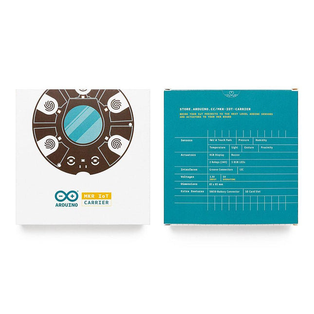
The MKR IoT Carrier comes equipped with 5 RGB LEDs, 5 capacitive touch buttons, a colored display, IMU and a variety of quality sensors. It also features a battery holder for a 18650 Li-Ion battery, SD card holder and Grove connectors.
Data Capture: Map the environment around the carrier using the integrated temperature, humidity, and pressure sensors and collect data about movement using the 6 axis IMU and light, gesture, and proximity sensors. Easily add more external sensors to capture more data from more sources via the on-board Grove connectors (x3).
Data Storage: Capture and store all the data locally on an SD card, or connect to the Arduino IoT Cloud for real-time data capture, storage, and visualization.
Data Visualisation: Locally view real-time sensor readings on the built-in OLED Color Display and create visual or sound prompts using the embedded LEDs and buzzer.
Total Control: Directly control small-voltage electronic appliances using the onboard relays and the five tactile buttons, with the integrated display providing a handy on-device interface for immediate control.
Programming and Projects for the Minima and WiFi
Based on the low-cost 8-bit ATmega328P processor, the Arduino Uno R3 board is likely to score as the most popular Arduino family member, and this workhorse has been with us for many years. Eleven years later, the long-overdue successor, the Arduino Uno R4, was released. It is built around a 48 MHz, 32-bit Arm Cortex-M4 microcontroller and provides significantly expanded SRAM and Flash memory. Additionally, a higher-precision ADC and a new DAC are added to the design. The Uno R4 board also supports the CAN Bus with an interface.
Two versions of the board are available: Uno R4 Minima, and Uno R4 WiFi. This book is about using these new boards to develop many different and interesting projects with just a handful of parts and external modules. All projects described in the book have been fully tested on the Uno R4 Minima or the Uno R4 WiFi board, as appropriate.
The project topics include the reading, control, and driving of many components and modules in the kit as well as on the relevant Uno R4 board, including
LEDs
7-segment displays (using timer interrupts)
LCDs
Sensors
RFID Reader
4x4 Keypad
Real-time clock (RTC)
Joystick
8×8 LED matrix
Motors
DAC (Digital-to-analog converter)
LED matrix
WiFi connectivity
Serial UART
CAN bus
Infrared controller and receiver
Simulators
… all in creative and educational ways with the project operation and associated software explained in great detail.
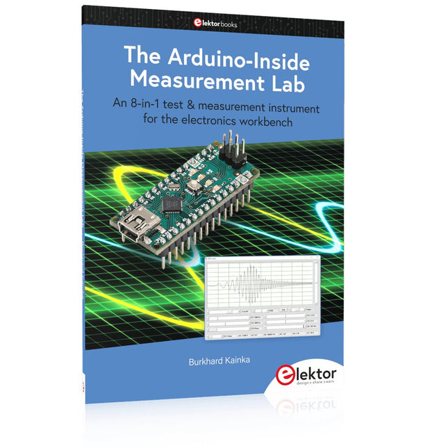
An 8-in-1 test & measurement instrument for the electronics workbench
A well-equipped electronics lab is crammed with power supplies, measuring devices, test equipment and signal generators. Wouldn‘t it be better to have one compact device for almost all tasks? Based on the Arduino, a PC interface is to be developed that’s as versatile as possible for measurement and control. It simply hangs on a USB cable and – depending on the software – forms the measuring head of a digital voltmeter or PC oscilloscope, a signal generator, an adjustable voltage source, a frequency counter, an ohmmeter, a capacitance meter, a characteristic curve recorder, and much more.
The circuits and methods collected here are not only relevant for exactly these tasks in the "MSR" electronics lab, but many details can also be used within completely different contexts.
Errata/Updates
In the programs printed, all instances of “be()” should read: sei().
,
by Lobna Belarbi
Must-Have Boards, Kits & Tools to Start Your Arduino Journey with Elektor
Whether you're a newcomer eager to explore the world of microcontrollers or an experienced maker seeking to expand your toolkit, Elektor offers a curated selection...