Elektor GREEN and GOLD members can download their digital edition here.
Not a member yet? Click here.
Arduino Portenta Machine Control and Arduino Portenta H7A CAN-to-MQTT Gateway Demo Project
Unboxing the Elektor LCR Meter with David Cuartielles
MicroPython Enters the World of Arduino
Connected Projects, SimplifiedDive Into the Arduino Cloud
Introduction to TinyMLBig Is Not Always Better
Arduino K-Way
Writing Arduino Sketches Just Got Better
Get to Know Arduino
Getting Started with the Portenta X8Manage Software Securely with Containers
Build, Deploy, and Maintain Scalable, Secure ApplicationsWith Arduino Portenta X8 Featuring NXP’s i.MX 8M Mini Applications Processor and EdgeLock SE050 Secure Element
How I Automated My HomeArduino CEO Fabio Violante Shares Solutions
Altair 8800 SimulatorHardware Simulation of a Vintage Computer
MS-DOS on the Portenta H7Run Old-School Software on Contemporary Hardware
Grow It YourselfA Digitally Controlled, Single-Box Solution for Indoor Farming
Save the Planet With Home Automation?MQTT on the Arduino Nano RP2040 Connect
Go Professional with Arduino Pro
Smart Ovens Take a Leap Into the Future
Tagvance Builds Safer Construction Sites with Arduino
Santagostino Breathes Easywith Remote Monitoring that Leverages AI for Predictive Maintenance
Security Flies High with RIoT Secure’s MKR-Based Solution
Open-Source Brings a New Generation of Water Management to the World
SensoDetect Deforestation with Sound Analysis
The Mozzi Arduino Library for Sound SynthesisInsights from Tim Barrass
The New Portenta X8 (with Linux!) and Max Carrier Redefine What’s Possible
How Using Arduino Helps Students Build Future Skills
Must-Haves for Your Electronics Workspace
The Importance of Robotics in Education
Dependable IoT Based Upon LoRa
Unboxing the Portenta Machine Control
8-Bit Gaming with Arduboy
Reducing Water Usage at Horseback Riding TracksAn IoT to Constantly Monitor Soil Humidity and Temperature Levels
The Panettone ProjectA sourdough starter management and maintenance system
Supporting Arduino Resellers
Space Invaders with Arduino
Art with ArduinoInspiring Insights from Artists and Designers
Arduino Product Catalogue
The Future of Arduino
Make your project dreams come true: an odometer for the hamster wheel, a fully automatic control of your ant farm with web interface, or the Sandwich-O-Mat – a machine that toasts and grills sandwiches of your choice.
With the Arduino and the DIY or Maker movement, not only did entry into microcontroller programming become child's play, but a second development also took place: Resourceful developers brought small boards – so-called shields or modules – to the market, which greatly simplified the use of additional hardware. The small modules contain all the important electronic parts to be connected to the microcontroller with a few plug-in cables, eliminating the need for a fiddly and time-consuming assembly on the plug-in board. In addition, it is also possible to handle tiny components that do not have any connecting legs (so-called SMDs).
Projects Discussed
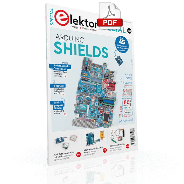
Arduino seeks connection
BMP and introduction to libraries, I²C
Learn I/O basics with the multi-purpose shield
I²C LCD adapter and DOT matrix displays
LCD keypad shield
Level converter
W5100: Internet connection
I/O expansion shield
Relays and solid-state relays
The multi-function shield: A universal control unit
Connecting an SD card reader via SPI
Keys and 7-segment displays
16-bit ADC
MCP4725 DAC
16-way PWM servo driver
MP3 player
GPS data logger using an SD card
Touch sensor
Joystick
SHT31: Temperature and humidity
VEML6070 UV-A sensor
VL53L0X time-of-flight
Ultrasonic distance meter
MAX7219-based LED DOT matrix display
DS3231 RTC
Port expander MCP23017
433 MHz radio
MPU-650 gyroscope
ADXL345 accelerometer
WS2812 RGB LEDs
Power supply
MQ-xx gas sensors
CO2 gas sensor
ACS712 current sensor
INA219 current sensor
L298 motor driver
MFRC522 RFID
28BYJ-48 stepper motor
TMC2209 silent step stick
X9C10x digital potentiometer
ST7735 in a color TFT display
e-Paper display
Bluetooth
Geiger counter
SIM800L GSM module
I²C multiplexer
Controller Area Network
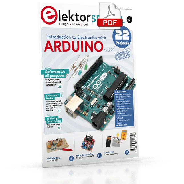
Although the Arduino isn’t a novelty any longer, there are still many beginners who want to try programming and development with a microcontroller, and to them, it is all new. All beginnings can be difficult, though they should be light and enjoyable.
You do not need much or expensive equipment for the examples. The circuits are built on a small breadboard, and, if necessary, connected to an Arduino Uno, which you can program on a Windows PC. You will find clear examples of how to build all circuits, ensuring easy and error-free reproduction.
Projects Discussed
Current & Voltage – How it all began
Arduino Hardware
Arduino Programming
The Electrical Circuit
Measuring with the Multimeter
Circuit Diagrams and Breadboards
Creating Circuit Diagrams
Breadboard Views with Fritzing
Online Circuit Simulation
Indispensable: Resistors (Part 1)
Hands-on with Resistors (Part 2)
Variable Resistors
Diodes: One-way Street for Current
The Transistor Switch
Electromagnetism
Relays and Motors
op-amps: Operational Amplifiers
Capacitors
The NE555 Timer
PWM and Analogue Values with Arduino
7-Segment Temperature Display
Introduction to Soldering and LCDs
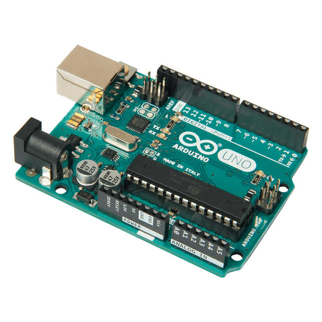
Arduino Uno is an open-source microcontroller board based on the ATmega328P. It has 14 digital input/output pins (of which 6 can be used as PWM outputs), 6 analog inputs, a 16 MHz ceramic resonator (CSTCE16M0V53-R0), a USB connection, a power jack, an ICSP header and a reset button. It contains everything needed to support the microcontroller; simply connect it to a computer with a USB cable or power it with a AC-to-DC adapter or battery to get started. You can tinker with your Uno without worring too much about doing something wrong, worst case scenario you can replace the chip for a few dollars and start over again.
'Uno' means one in Italian and was chosen to mark the release of Arduino Software (IDE) 1.0. The Uno board and version 1.0 of Arduino Software (IDE) were the reference versions of Arduino, now evolved to newer releases. The Uno board is the first in a series of USB Arduino boards, and the reference model for the Arduino platform; for an extensive list of current, past or outdated boards see the Arduino index of boards.
Specifications
Microcontroller
ATmega328P
Operating Voltage
5 V
Input Voltage (recommended)
7-12 V
Input Voltage (limit)
6-20 V
Digital I/O Pins
14 (of which 6 provide PWM output)
PWM Digital I/O Pins
6
Analog Input Pins
6
DC Current per I/O Pin
20 mA
DC Current for 3.3 V Pin
50 mA
Flash Memory
32 KB (ATmega328P) of which 0.5 KB used by bootloader
SRAM
2 KB (ATmega328P)
EEPROM
1 KB (ATmega328P)
Clock Speed
16 MHz
LED_BUILTIN
13
Dimensions
68.6 x 53.4 mm
Weight
25 g
The Elektor MultiCalculator Kit is an Arduino-based multifunction calculator that goes beyond basic calculations. It offers 22 functions including light and temperature measurement, differential temperature analysis, and NEC IR remote control decoding. The Elektor MultiCalculator is a handy tool for use in your projects or for educational purposes.
The kit features a Pro Mini module as the computing unit. The PCB is easy to assemble using through-hole components. The enclosure consists of 11 acrylic panels and mounting materials for easy assembly. Additionally, the device is equipped with a 16x2 alphanumeric LCD, 20 buttons, and temperature sensors.
The Elektor MultiCalculator is programmable with the Arduino IDE through a 6-way PCB header. The available software is bilingual (English and Dutch). The calculator can be programmed with a programming adapter, and it is powered through USB-C.
Modes of Operation
Calculator
4-Ring Resistor Code
5-Ring Resistor Code
Decimal to Hexadecimal and Character (ASCII) conversion
Hexadecimal to Decimal and Character (ASCII) conversion
Decimal to Binary and Character (ASCII) conversion
Binary to Decimal and Hexadecimal conversion
Hz, nF, capacitive reactance (XC) calculation
Hz, µH, inductive reactance (XL) calculation
Resistance calculation of two resistors connected in parallel
Resistance calculation of two resistors connected in series
Calculation of unknown parallel resistor
Temperature measurement
Differential temperature measurement T1&T2 and Delta (δ)
Light measurement
Stopwatch with lap time function
Item counter
NEC IR remote control decoding
AWG conversion (American Wire Gauge)
Rolling Dice
Personalize startup message
Temperature calibration
Specifications
Menu languages: English, Dutch
Dimensions: 92 x 138 x 40 mm
Build time: approx. 5 hours
Included
PCB and though-hole components
Precut acrylic sheets with all mechanical parts
Pro Mini microcontroller module (ATmega328/5 V/16 MHz)
Programming adapter
Waterproof temperature sensors
USB-C cable
Downloads
Software
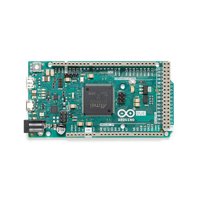
The board contains everything needed to support the microcontroller; simply connect it to a computer with a micro-USB cable or power it with an AC-to-DC adapter or battery to get started. The Due is compatible with all Arduino shields that work at 3.3V and are compliant with the 1.0 Arduino pinout.
The Due follows the 1.0 pinout:
TWI: SDA and SCL pins that are near to the AREF pin.
IOREF: allows an attached shield with the proper configuration to adapt to the voltage provided by the board. This enables shield compatibility with a 3.3V board like the Due and AVR-based boards which operate at 5V.
An unconnected pin, reserved for future use.
Specifications
Operating Voltage
3.3 V
Input Voltage
7-12 V
Digital I/O
54
Analog Input Pins
12
Analog Output Pins
2 (DAC)
Total DC Output Current on all I/O Lines
130 mA
DC Current per I/O Pin
20 mA
DC Current for 3.3 V Pin
800 mA
DC Current for 5 V Pin
800 mA
Flash Memory
512 KB all available for the user applications
SRAM
96 KB
Clock Speed
84 MHz
Length
101.52 mm
Width
53.3 mm
Weight
36 g
Please note: Unlike most Arduino boards, the Arduino Due board runs at 3.3V. The maximum voltage that the I/O pins can tolerate is 3.3V. Applying voltages higher than 3.3V to any I/O pin could damage the board.
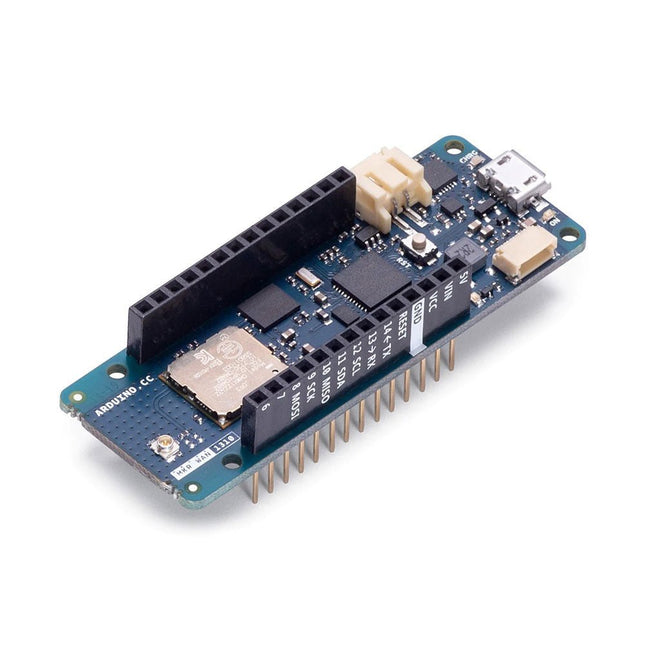
The board's main processor is a low-power ARM Cortex-M0 32-bit SAMD21, like in the other boards within the Arduino MKR family. The WiFi and Bluetooth connectivity is performed with a module from u-blox, the NINA-W10, a low-power chipset operating in the 2.4 GHz range. On top of that, secure communication is ensured through the Microchip ECC508 crypto chip. Besides that, you can find a battery charger, and an RGB LED on-board.
Official Arduino WiFi Library
You can get your board to connect to any kind of existing WiFi network, or use it to create your own Arduino Access Point. The specific set of examples we provide for the MKR WiFi 1010 can be consulted at the WiFiNINA library reference page.
Compatible with other Cloud Services
It is also possible to connect your board to different Cloud services, Arduino's own among others. Here are some examples of how to get the MKR WiFi 1010 to connect to:
Blynk: a simple project from the Arduino community connecting to Blynk to operate your board from a phone with little code
IFTTT: in-depth case of building a smart plug connected to IFTTT
AWS IoT Core: Arduino made this example on how to connect to Amazon Web Services
Azure: visit this GitHub repository explaining how to connect a temperature sensor to Azure's Cloud
Firebase: you want to connect to Google's Firebase, this Arduino library will show you how
Specifications
Microcontroller
SAMD21 Cortex-M0+ 32bit low power ARM MCU
Radio Module
u-blox NINA-W102
Power Supply
5 V
Secure Element
ATECC508
Supported Battery
Li-Po Single Cell, 3.7 V, 1024 mAh Minimum
Operating Voltage
3.3 V
Digital I/O Pins
8
PWM Pins
13
UART
1
SPI
1
I2C
1
Analog Input Pins
7
Analog Output Pins
1
External Interrupts
10
Flash Memory
256 KB
SRAM
32 KB
EEPROM
No
Clock Speed
32.768 kHz, 48 MHz
LED_Builtin
6
USB
Full-Speed USB Device and embedded Host
Length
61.5 mm
Width
25 mm
Weight
32 g
The Arduino MKR Zero is a development board for music makers! With an SD card holder and dedicated SPI interfaces (SPI1), you are able to play music files without extra hardware.
The MKR Zero brings you the power of a Zero in the smaller format established by the MKR form factor. The MKR Zero board acts as a great educational tool for learning about 32-bit application development. It has an on-board SD connector with dedicated SPI interfaces (SPI1) that allows you to play with MUSIC files with no extra hardware! The board is powered by Atmel’s SAMD21 MCU, which features a 32-bit ARM Cortex M0+ core.
The board contains everything needed to support the microcontroller; simply connect it to a computer with a micro-USB cable or power it by a LiPo battery. The battery voltage can also be monitored since a connection between the battery and the analog converter of the board exists.
Specifications
Microcontroller
SAMD21 ARM Cortex-M0+ 32-bit low power
Board power supply (USB/VIN)
5 V
Supported battery
Li-Po single cell, 3.7 V, 700 mAh minimum
DC current for 3.3 V pin
600 mA
DC current for 5 V pin
600 mA
Circuit operating voltage
3.3 V
Digital I/O pins
22
PWM pins
12 (0, 1, 2, 3, 4, 5, 6, 7, 8, 10, A3 - or 18 -, A4 -or 19)
UART
1
SPI
1
I²C
1
Analog input pins
7 (ADC 8/10/12 bit)
Analog output pins
1 (DAC 10 bit)
External interrupts
10 (0, 1, 4, 5, 6, 7, 8, A1 -or 16-, A2 - or 17)
DC current per I/O pin
7 mA
Flash memory
256 KB
Flash memory for bootloader
8 KB
SRAM
32 KB
EEPROM
No
Clock speed
32.768 kHz (RTC), 48 MHz
LED_BUILTIN
32
Downloads
Datasheet
Eagle Files
Schematics
Fritzing
Pinout
Ever wanted an automated house? Or a smart garden? Well, now it’s easy with the Arduino IoT Cloud compatible boards. It means: you can connect devices, visualize data, control and share your projects from anywhere in the world. Whether you’re a beginner or a pro, we have a wide range of plans to make sure you get the features you need.
Connect your sensors and actuators over long distances harnessing the power of the LoRa wireless protocol or throughout LoRaWAN networks.
The Arduino MKR WAN 1310 board provides a practical and cost effective solution to add LoRa connectivity to projects requiring low power. This open source board can be connected to the Arduino IoT Cloud.
Better and More Efficient
The MKR WAN 1310, brings in a series of improvements when compared to its predecessor, the MKR WAN 1300. While still based on the Microchip SAMD21 low power processor, the Murata CMWX1ZZABZ LoRa module, and the MKR family’s characteristic crypto chip (the ECC508), the MKR WAN 1310 includes a new battery charger, a 2 MByte SPI Flash, and improved control of the board’s power consumption.
Improved Battery Power
The latest modifications have considerably improved the battery life on the MKR WAN 1310. When properly configured, the power consumption is now as low as 104 uA! It is also possible to use the USB port to supply power (5 V) to the board; run the board with or without batteries – the choice is yours.
On-board Storage
Data logging and other OTA (Over The Air) functions are now possible since the inclusion of the on board 2 MByte Flash. This new exciting feature will let you transfer configuration files from the infrastructure onto the board, create your own scripting commands, or simply store data locally to send it whenever the connectivity is best. Whilst the MKR WAN 1310’s crypto chip adds further security by storing credentials & certificates in the embedded secure element.
These features make it the perfect IoT node and building block for low-power wide-area IoT devices.
Specifications
The Arduino MKR WAN 1310 is based on the SAMD21 microcontroller.
Microcontroller
SAMD21 Cortex-M0+ 32-bit low power ARM MCU (datasheet)
Radio module
CMWX1ZZABZ (datasheet)
Board power supply (USB/VIN)
5 V
Secure element
ATECC508 (datasheet)
Supported batteries
Rechargeable Li-Ion, or Li-Po, 1024 mAh minimum capacity
Circuit operating voltage
3.3 V
Digital I/O pins
8
PWM pins
13 (0 .. 8, 10, 12, 18 / A3, 19 / A4)
UART
1
SPI
1
I²C
1
Analog input pins
7 (ADC 8/10/12 bit)
Analog output pins
1 (DAC 10 bit)
External interrupts
8 (0, 1, 4, 5, 6, 7, 8, 16 / A1, 17 / A2)
DC current per I/O pin
7 mA
CPU flash memory
256 KB (internal)
QSPI flash memory
2 MByte (external)
SRAM
32 KB
EEPROM
No
Clock speed
32.768 kHz (RTC), 48 MHz
LED_BUILTIN
6
USB
Full-Speed USB Device and embedded Host
Antenna gain
2 dB (bundled pentaband antenna)
Carrier frequency
433/868/915 MHz
Dimensions
67.64 x 25 mm
Weight
32 g
Downloads
Eagle Files
Schematics
Fritzing
Pinout
Arduino MKR NB 1500 allows you to build your next smart project.
Ever wanted an automated house? Or a smart garden? Well, now it’s easy with the Arduino IoT Cloud compatible boards. It means: you can connect devices, visualize data, control and share your projects from anywhere in the world. Whether you’re a beginner or a pro, we have a wide range of plans to make sure you get the features you need.
Add Narrowband communication to your project with the MKR NB 1500. It's the perfect choice for devices in remote locations without an Internet connection, or in situations in which power isn't available like on-field deployments, remote metering systems, solar-powered devices, or other extreme scenarios.
The board's main processor is a low power ARM Cortex-M0 32-bit SAMD21, like in the other boards within the Arduino MKR family. The Narrowband connectivity is performed with a module from u-blox, the SARA-R410M-02B, a low power chipset operating in the de different bands of the IoT LTE cellular range. On top of those, secure communication is ensured through the Microchip ECC508 crypto chip. Besides that, the pcb includes a battery charger, and a connector for an external antenna.
This board is designed for global use, providing connectivity on LTE's Cat M1/NB1 bands 1, 2, 3, 4, 5, 8, 12, 13, 18, 19, 20, 25, 26, 28. Operators offering service in that part of the spectrum include: Vodafone, AT&T, T-Mobile USA, Telstra, and Verizon, among others.
Specifications
The Arduino MKR NB 1500 is based on the SAMD21 microcontroller.
Microcontroller
SAMD21 Cortex-M0+ 32-bit low power ARM MCU (datasheet)
Radio module
u-blox SARA-R410M-02B (datasheet summary)
Secure element
ATECC508 (datasheet)
Board power supply (USB/VIN)
5 V
Supported battery
Li-Po Single Cell, 3.7 V, 1500 mAh Minimum
Circuit operating voltage
3.3 V
Digital I/O pins
8
PWM pins
13 (0 .. 8, 10, 12, 18 / A3, 19 / A4)
UART
1
SPI
1
I²C
1
Analog input pins
7 (ADC 8/10/12 bit)
Analog output pins
1 (DAC 10 bit)
External interrupts
8 (0, 1, 4, 5, 6, 7, 8, 16 / A1, 17 / A2)
DC current per I/O pin
7 mA
Flash memory
256 KB (internal)
SRAM
32 KB
EEPROM
No
Clock speed
32.768 kHz (RTC), 48 MHz
LED_BUILTIN
6
USB
Full-speed USB device and embedded host
Antenna gain
2 dB
Carrier frequency
LTE bands 1, 2, 3, 4, 5, 8, 12, 13, 18, 19, 20, 25, 26, 28
Power class (radio)
LTE Cat M1 / NB1: Class 3 (23 dBm)
Data rate (LTE M1 halp-duplex)
UL 375 kbps / DL 300 kbps
Data rate (LTE NB1 full-duplex)
UL 62.5 kbps / DL 27.2 kbps
Working region
Multiregion
Device location
GNSS via modem
Power consumption (LTE M1)
min 100 mA / max 190 mA
Power consumption (LTE NB1)
min 60 mA / max 140 mA
SIM card
MicroSIM (not included with the board)
Dimensions
67.6 x 25 mm
Weight
32 g
Downloads
Eagle Files
Schematics
Pinout
This USB Stick contains more than 300 Arduino-related articles published in Elektor Magazine. The content includes both background articles and projects on the following topics:
Software & hardware development: Tutorials on Arduino software development using Arduino IDE, Atmel Studio, Shields, and essential programming concepts.
Learning: The Microcontroller Bootcamp offers a structured approach to programming embedded systems.
Data acquisition & measurement: Projects such as a 16-bit data logger, lathe tachometer, and an AC grid analyzer for capturing and analyzing real-time signals.
Wireless communication: Learn how to implement wireless networks, create an Android interface, and communicate effectively with microcontrollers.
Robotics and automation: This covers the Arduino Nano Robot Controller, supporting boards for automation, and explores various Arduino shields to enhance functionality.
Self-build projects: Unique projects such as laser projection, Numitron clock and thermometer, ELF receiver, Theremino, and touch LED interfaces highlight creative applications.
Whether you're a beginner or an experienced maker, this collection is a valuable resource for learning, experimenting, and pushing the boundaries of Arduino technology.
The Arduino Pro Portenta Vision Shield LoRa brings industry-rated features to your Portenta. This hardware add-on will let you run embedded computer vision applications, connect wirelessly via LoRa to the Arduino Cloud or your own infrastructure, and activate your system upon the detection of sound events.
The shield comes with:
a 320x320 pixels camera sensor: use one of the cores in Portenta to run image recognition algorithms using the OpenMV for Arduino editor
long range 868/915 MHz LoRa wireless connectivity: get your Portenta H7 connected to the Internet of Things with low power consumption
two on-board microphones for directional sound detection: capture and analyse sound in real-time
JTAG connector: perform low-level debugging of your Portenta board or special firmware updates using an external programmer
SD-Card connector: store your captured data in the card, or read configuration files
The Vision Shield LoRa has been designed to work with the Arduino Portenta H7. The Portenta boards feature multicore 32-bit ARM Cortex processors running at hundreds of megahertz, with megabytes of program memory and RAM. Portenta boards come with WiFi and Bluetooth.
Specifications
Camera
Himax HM-01B0 camera module (manufacturer site)
Resolution
320 x 320 active pixel resolution with support for QVGA
Image sensor
High sensitivity 3.6μ BrightSense pixel technology
Microphone
2x MP34DT05 (datasheet)
Connectivity
868/915MHz ABZ-093 LoRa Module with ARM Cortex-M0+ (datasheet)
Dimensions
66 x 25 mm
Weight
8 g
Downloads
Datasheet
Schematics