Search results for "45 OR elektronik OR projekte OR fur OR den OR raspberry OR pi OR pdf"
-
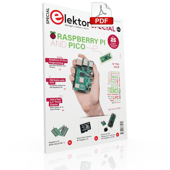
Elektor Digital Elektor Special: Raspberry Pi and Pico (PDF)
Contents Projects PicoVoiceVoice alienation and sound effects with the Raspberry Pi Pico Navigation with Vibration Feedback POV Display Pulse Width Modulation (PWM) with the Raspberry Pi Pico Wi-Fi with the Raspberry Pi Pico 'Hello World' from the Raspberry Pi Pico and RP2040A look at the Raspberry Pi Foundation’s first microcontroller Simple On-Off Temperature Controller with Raspberry Pi HAT Multitasking with the Raspberry PiShowcase: a traffic lights controller The Raspberry Pi Ruler GadgetFun with a time-of-flight sensor Raspberry Pi Buffer Board (Mk. 1)Never blow up the I/O again FM radio with RDSA top HAT project for the Raspberry Pi LoRa with the Raspberry Pi PicoFun with MicroPython! Tutorials Qt for the Raspberry Pi Raspberry Pi Pico Programmingwith MicroPython and Thonny Raspberry Pi Full StackRPi and RF24 at the heart of a sensor network Raspberry Pi Bash Command Cheat Sheet Community Java on the Raspberry PiAn interview with Frank Delporte Reviews Introducing the New Raspberry Pi Pico W, H, and WH Secure Boot Solution for Raspberry PiRetrofit security at a reasonable price Review: SmartPi – Smart Meter Extension for Raspberry Pi Review: The Enviro+ Raspberry Pi HATMeasuring environmental data with Raspberry Pi and the HAT Enviro+ Review: Meet the Raspberry Pi 4All new but still good? Raspberry Pi Gets a Fast 3.5' Touch DisplayMore power at no extra charge Book Launch: Raspberry Pi for Radio Amateurs
€ 11,95
Members € 10,76
-
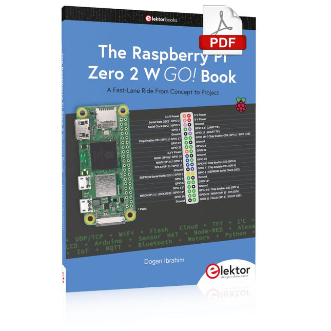
Elektor Digital The Raspberry Pi Zero 2 W GO! Book (PDF)
A Fast-Lane Ride From Concept to Project The core of the book explains the use of the Raspberry Pi Zero 2 W running the Python programming language, always in simple terms and backed by many tested and working example projects. On part of the reader, familiarity with the Python programming language and some experience with one of the Raspberry Pi computers will prove helpful. Although previous electronics experience is not required, some knowledge of basic electronics is beneficial, especially when venturing out to modify the projects for your own applications. Over 30 tested and working hardware-based projects are given in the book, covering the use of Wi-Fi, communication with smartphones and with a Raspberry Pi Pico W computer. Additionally, there are Bluetooth projects including elementary communication with smartphones and with the popular Arduino Uno. Both Wi-Fi and Bluetooth are key features of the Raspberry Pi Zero 2 W. Some of the topics covered in the book are: Raspberry Pi OS installation on an SD card Python program creation and execution on the Raspberry Pi Zero 2 W Software-only examples of Python running on the Raspberry Pi Zero 2 W Hardware-based projects including LCD and Sense HAT interfacing UDP and TCP Wi-Fi based projects for smartphone communication UDP-based project for Raspberry Pi Pico W communication Flask-based webserver project Cloud storage of captured temperature, humidity, and pressure data TFT projects Node-RED projects Interfacing to Alexa MQTT projects Bluetooth-based projects for smartphone and Arduino Uno communications
€ 32,95
Members € 26,36
-
Raspberry Pi Foundation Bumper for Raspberry Pi 5
The Raspberry Pi Bumper is a snap-on silicone cover that protects the bottom and edges of the Raspberry Pi 5. Features One-piece flexible silicone rubber bumper Enables easy access to the power button Mounting holes remain accessible underneath the bumper Downloads Datasheet
€ 3,50€ 1,40
Members identical
-
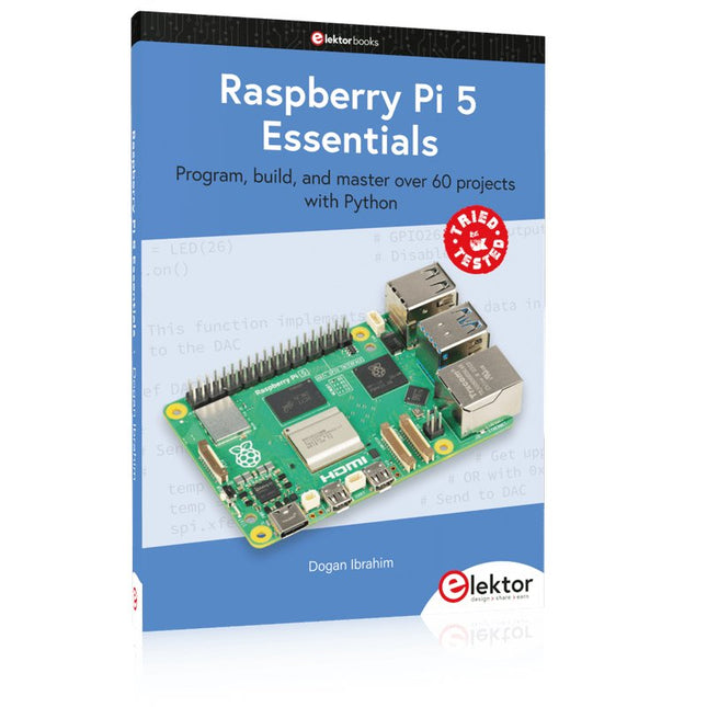
Elektor Publishing Raspberry Pi 5 Essentials
Program, build, and master over 60 projects with Python The Raspberry Pi 5 is the latest single-board computer from the Raspberry Pi Foundation. It can be used in many applications, such as in audio and video media centers, as a desktop computer, in industrial controllers, robotics, and in many domestic and commercial applications. In addition to the well-established features found in other Raspberry Pi computers, the Raspberry Pi 5 offers Wi-Fi and Bluetooth (classic and BLE), which makes it a perfect match for IoT as well as in remote and Internet-based control and monitoring applications. It is now possible to develop many real-time projects such as audio digital signal processing, real-time digital filtering, real-time digital control and monitoring, and many other real-time operations using this tiny powerhouse. The book starts with an introduction to the Raspberry Pi 5 computer and covers the important topics of accessing the computer locally and remotely. Use of the console language commands as well as accessing and using the desktop GUI are described with working examples. The remaining parts of the book cover many Raspberry Pi 5-based hardware projects using components and devices such as LEDs and buzzers LCDs Ultrasonic sensors Temperature and atmospheric pressure sensors The Sense HAT Camera modules Example projects are given using Wi-Fi and Bluetooth modules to send and receive data from smartphones and PCs, and sending real-time temperature and atmospheric pressure data to the cloud. All projects given in the book have been fully tested for correct operation. Only basic programming and electronics experience are required to follow the projects. Brief descriptions, block diagrams, detailed circuit diagrams, and full Python program listings are given for all projects described.
€ 39,95
Members € 35,96
-
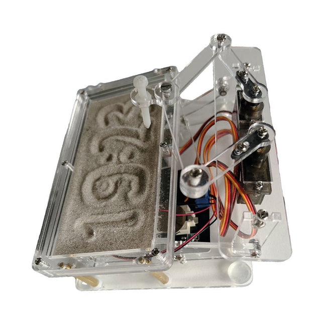
Elektor Labs Elektor Sand Clock for Raspberry Pi Pico
Raspberry Pi-based Eye Catcher A standard sand clock just shows how time passes. In contrast, this Raspberry Pi Pico-controlled sand clock shows the exact time by “engraving” the four digits for hour and minute into the layer of sand. After an adjustable time the sand is flattened out by two vibration motors and everything begins all over again. At the heart of the sand clock are two servo motors driving a writing pen through a pantograph mechanism. A third servo motor lifts the pen up and down. The sand container is equipped with two vibration motors to flatten the sand. The electronic part of the sand clock consists of a Raspberry Pi Pico and an RTC/driver board with a real-time clock, plus driver circuits for the servo motors. A detailed construction manual is available for downloading. Features Dimensions: 135 x 110 x 80 mm Build time: approx. 1.5 to 2 hours Included 3x Precut acrylic sheets with all mechanical parts 3x Mini servo motors 2x Vibration motors 1x Raspberry Pi Pico 1x RTC/driver board with assembled parts Nuts, bolts, spacers, and wires for the assembly Fine-grained white sand
€ 49,95€ 39,95
Members identical
-
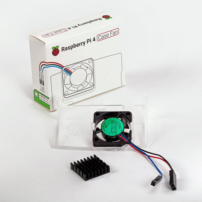
Raspberry Pi Foundation Raspberry Pi 4 Case Fan
Designed for overclockers and other power users, this fan keeps your Raspberry Pi 4 at a comfortable operating temperature even under heavy load. The temperature-controlled fan delivers up to 1.4 CFM of airflow over the processor, memory, and power management IC. The bundled heatsink (18 x 8 x 10 mm) with self-adhesive pad improves heat transfer from the processor. The Raspberry Pi 4 Case Fan works with Raspberry Pi 4 and the official Raspberry Pi 4 case.
€ 6,95€ 2,78
Members identical
-

Elektor Digital Explore the Raspberry Pi in 45 Electronics Projects (3rd Edition | E-book)
3rd Edition – Fully updated for Raspberry Pi 4 The Raspberry Pi is a very cheap but complete computer system that allows all sorts of electronics parts and extensions to be connected. This book addresses one of the strongest aspects of the Raspberry Pi: the ability to combine hands-on electronics and programming. Combine hands-on electronics and programming After a short introduction to the Raspberry Pi you proceed with installing the required software. The SD card that can be purchased in conjunction with this book contains everything to get started with the Raspberry Pi. At the side of the (optional) Windows PC, software is used which is free for downloading. The book continues with a concise introduction to the Linux operating system, after which you start programming in Bash, Python 3 and Javascript. Although the emphasis is on Python, the coverage is brief and to the point in all cases – just enabling you to grasp the essence of all projects and start adapting them to your requirements. All set, you can carry on with fun projects. The book is ideal for self-study No fewer than 45 exciting and compelling projects are discussed and elaborated in detail. From a flashing lights to driving an electromotor; from processing and generating analog signals to a lux meter and a temperature control. We also move to more complex projects like a motor speed controller, a web server with CGI, client-server applications and Xwindows programs. Each project has details of the way it got designed that way The process of reading, building, and programming not only provides insight into the Raspberry Pi, Python, and the electronic parts used, but also enables you to modify or extend the projects any way you like. Also, feel free to combine several projects into a larger design.
€ 32,95
Members € 26,36
-
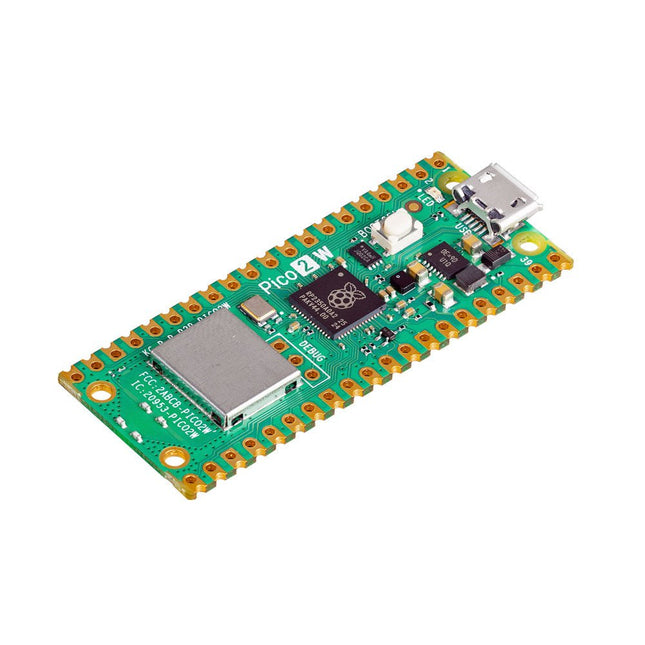
Raspberry Pi Foundation Raspberry Pi Pico 2 W
The Raspberry Pi Pico 2 W is a microcontroller board based on the RP2350 featuring 2.4 GHz 802.11n wireless LAN and Bluetooth 5.2. It gives you even more flexibility in your IoT or smart product designs and expanding the possibilities for your projects. The RP2350 provides a comprehensive security architecture built around Arm TrustZone for Cortex-M. It incorporates signed boot, 8 KB of antifuse OTP for key storage, SHA-256 acceleration, a hardware TRNG, and fast glitch detectors. The unique dual-core, dual-architecture capability of the RP2350 allows users to choose between a pair of industry-standard Arm Cortex-M33 cores and a pair of open-hardware Hazard3 RISC-V cores. Programmable in C/C++ and Python, and supported by detailed documentation, the Raspberry Pi Pico 2 W is the ideal microcontroller board for both enthusiasts and professional developers. Specifications CPU Dual Arm Cortex-M33 or dual RISC-V Hazard3 processors @ 150 MHz Wireless On-board Infineon CYW43439 single-band 2.4 GHz 802.11n wireless Lan and Bluetooth 5.2 Memory 520 KB on-chip SRAM; 4 MB on-board QSPI flash Interfaces 26 multi-purpose GPIO pins, including 4 that can be used for AD Peripherals 2x UART 2x SPI controllers 2x I²C controllers 24x PWM channels 1x USB 1.1 controller and PHY, with host and device support 12x PIO state machines Input power 1.8-5.5 V DC Dimensions 21 x 51 mm Downloads Datasheet Pinout Schematic
€ 7,95
Members identical
-
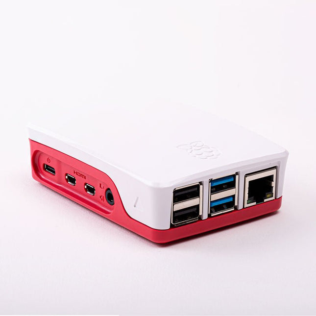
Raspberry Pi Foundation Official Case for Raspberry Pi 4 (white/red)
Official Case for Raspberry Pi 4 (white/red)
€ 7,95€ 3,18
Members identical
-
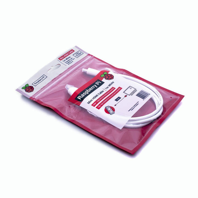
Raspberry Pi Foundation Official Mini-HDMI Cable for Raspberry Pi Zero
The official Raspberry Pi mini-HDMI to HDMI (A/M) cable designed for all Raspberry Pi Zero models. 19-pin HDMI Type D(M) to 19-pin HDMI Type A(M) 1 m cable (white) Nickel-plated plugs 4Kp60 compliant RoHS compliant 3 Mohm 300 VDC insulation, withstands 300 VDC for 0.1s
€ 3,95€ 1,58
Members identical
-

Raspberry Pi Foundation Official Case for Raspberry Pi 3 A+ (white/red)
The Raspberry Pi A+ Case has been designed to fit both the Pi 3 Model A+ and the Pi 1 Model A+. The high-quality ABS construction consists of two parts. The base features cut-outs to allow access to the microSD Card and the the HDMI, audio/video and USB ports, as well as the power connector.
€ 6,95€ 2,78
Members identical
-
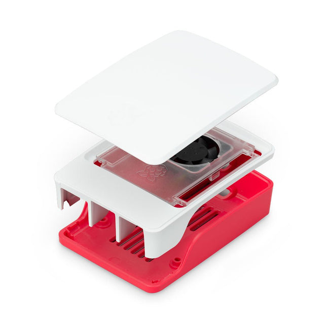
Raspberry Pi Foundation Official Case for Raspberry Pi 5 (white/red)
The Raspberry Pi 5 case is a refinement of the Raspberry Pi 4 case with improved thermal features to support the higher peak power consumption of the Raspberry Pi 5. It integrates a variable speed fan that is powered and controlled via a dedicated connector on the Raspberry Pi 5.
€ 11,95€ 4,78
Members identical


