Search results for "pages"
-
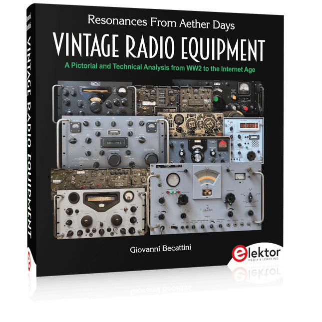
Elektor Publishing Vintage Radio Equipment
Resonances From Aether Days A Pictorial and Technical Analysis from WWII to the Internet Age From the birth of radio to the late 1980s, much of real life unfolded through shortwave communication. World War II demonstrated—beyond a shadow of a doubt—that effective communications equipment was a vital prerequisite for military success. In the postwar years, shortwave became the backbone on which many of the world's most critical services depended every day. All the radio equipment—through whose cathodes, grids, plates, and transistors so much of human history has flowed—is an exceptional subject of study and enjoyment for those of us who are passionate about vintage electronics. In this book, which begins in the aftermath of World War II, you’ll find a rich collection of information: descriptions, tips, technical notes, photos, and schematics that will be valuable for anyone interested in restoring—or simply learning about—these extraordinary witnesses to one of the most remarkable eras in technological history. My hope is that these pages will help preserve this vast treasure of knowledge, innovation, and history—a heritage that far transcends the purely technical.
€ 79,95
Members € 71,96
-
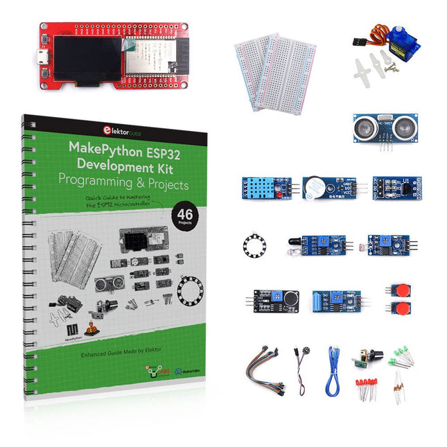
Elektor Bundles MakePython ESP32 Development Kit (EN)
Learn how to use the ESP32 Microcontroller and MicroPython programming in your future projects! The project book, written by well-known Elektor author Dogan Ibrahim, holds many software- and hardware-based projects especially developed for the MakePython ESP32 Development Kit. The kit comes with several LEDs, sensors, and actuators. The kit will help you acquire the basic knowledge to create IoT projects. The book’s fully evaluated projects feature all the supplied components. Each project includes a block diagram, a circuit diagram, a full program listing, and a complete program description. Included in the kit 1x MakePython ESP32 development board with LCD 1x Ultrasonic ranging module 1x Temperature and humidity sensor 1x Buzzer module 1x DS18B20 module 1x Infrared module 1x Potentiometer 1x WS2812 module 1x Sound sensor 1x Vibration sensor 1x Photosensitive resistance module 1x Pulse sensor 1x Servo motor 1x USB cable 2x Button 2x Breadboard 45x Jumper wire 10x Resistor 330R 10x LED (Red) 10x LED (Green) 1x Project book (206 pages) 46 Projects in the Book LED Projects Blinking LED Flashing SOS Blinking LED – using a timer Alternately flashing LEDs Button control Changing the LED flashing rate using pushbutton interrupts Chasing-LEDs Binary-counting LEDs Christmas lights (random-flashing 8 LEDs) Electronic dice Lucky day of the week Pulsewidth Modulation (PWM) Projects Generate a 1000-Hz PWM waveform with 50% duty cycle LED brightness control Measuring the frequency and duty cycle of a PWM waveform Melody maker Simple electronic organ Servo motor control Servo motor DS18B20 thermometer Analog To Digital Converter (ADC) Projects Voltmeter Plotting the analog input voltage ESP32 internal temperature sensor Ohmmeter Photosensitive resistance module Digital To Analog Converter (DAC) Projects Generating fixed voltages Generating a sawtooth-wave signal Generating a triangular-wave signal Arbitrary periodic waveform Generating a sinewave signal Generating accurate sinewave signal using timer interrupts Using The OLED Display Seconds counter Event counter DS18B20 OLED based digital thermometer ON-OFF temperature controller Measuring the temperature and humidity Ultrasonic distance measurement Height of a person (stadiometer) Heart rate (pulse) measurement Other Sensors Supplied with the Kit Theft alarm Sound-activated light Infrared obstacle avoidance with buzzer WS2812 RGB LED ring Timestamping temperature and humidity readings Network Programming Wi-Fi scanner Remote control from the Internet browser (using a smartphone or PC) – Web Server Storing temperature and humidity data in the Cloud Low-Power Operation Using a timer to wake up the processor
€ 89,95€ 69,95
Members identical
-
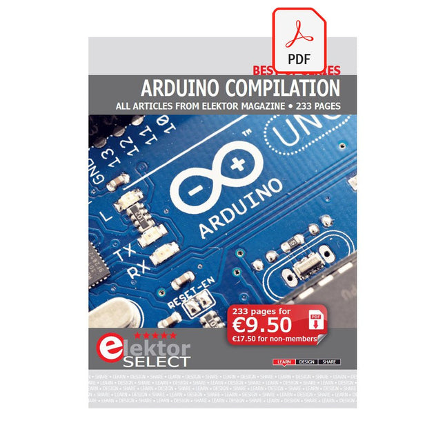
Elektor Digital Arduino Compilation (EN) | E-book
This 233-page e-book is packed with Arduino ideas, explanations, tips, diagrams, programs, PCB layouts, and more – enough to provide days of informative, inspiring, and stimulating reading pleasure! The PDF document includes a table of contents with links to the individual projects, allowing you to easily navigate to the sections you’re most interested in. This way, you can quickly and effortlessly switch between projects and find exactly what you’re looking for.
€ 9,95
Members € 7,96
-

Elektor Labs Elektor AM Transmitter Kit
Build Your Own Vintage Radio Broadcaster The Elektor AM Transmitter Kit allows streaming audio to vintage AM radio receivers. Based on a Raspberry Pi Pico microcontroller module, the AM Transmitter can transmit on 32 frequencies in the AM band, from 500 kHz up to 1.6 MHz in 32 steps of approx. 35 kHz. The frequency is selected with a potentiometer and shown on a 0.96" OLED display. A pushbutton allows toggles the transmitting mode between On and Off. The range of the transmitter depends on the antenna. The onboard antenna provides a range of a few centimeters, requiring the AM Transmitter to be placed close to or inside the radio. An external loop antenna (not included) can be connected to increase the range. The Elektor AM Transmitter Kit comes as a kit of parts that you must solder to the board yourself. Features The board is compatible with a Hammond 1593N enclosure (not included).A 5 VDC power supply with micro-USB connector (e.g., an old phone charger) is needed to power the kit (not included). Current consumption is 100 mA. The Arduino software (requiring Earle Philhower’s RP2040 Boards Package) for the Elektor AM Transmitter Kit plus more information is available at the Elektor Labs page of this project. Component List Resistors R1, R4 = 100 Ω R2, R3, R8 = 10 kΩ R5, R6, R9, R10, R11 = 1 kΩ R7 = optional (not included) P1 = potentiometer 100 kΩ, linear Capacitors C1 = 22 µF 16V C2, C4 = 10 nF C3 = 150 pF Miscellaneous K1 = 4×1 pin socket K2, K3 = 3.5 mm socket Raspberry Pi Pico pushbutton, angle mount 0.96" monochrome I²C OLED display PCB 150292-1
€ 34,95€ 29,95
Members identical
-

Elektor Classics The Complete Linear Audio Library (USB Stick)
Jan Didden created Linear Audio in 2010 and published 14 Volumes between 2010 and 2017. Each 200-page Volume contains on average 10 articles by expert authors in the field of audio, acoustics, and instrumentation. Whether you are interested in tube amplifiers, solid-state equipment, loudspeaker design, capacitor and resistor distortion or distortion measurement, you are certain to find helpful advice and interesting discussions. From beginner to advanced level, for the audio professional or the serious hobbyist, this ExpertCollection will advance your understanding and offer new perspectives on common issues. Bonus material included with this collection is a 5-part YouTube series on negative feedback as applied to audio by renowned author Jan Didden, and nine additional landmark audio articles and presentations. If you are seriously interested in audio, acoustics, and instrumentation, you can’t afford to miss this! The published material is indexed and fully searchable and will provide an almost limitless resource for many years to come. You can read about Linear Audio’s authors, and the Table of Contents of each Volume, at linearaudio.net.
€ 149,95€ 74,95
Members identical
-

Elektor Academy Pro ESP32 by Example (Learning Course)
Complete ESP32 microcontroller learning course featuring a custom-designed MCU expansion board, hands-on projects, and a comprehensive online guide – perfect for learning hardware, programming, and connectivity step by step. A Practical Introduction to Embedded Systems with the ESP32 This course is designed for readers who are new to embedded systems and looking for a structured, example-driven way to get started. If you’ve explored general-purpose electronics or Arduino-based materials but found them too broad or lacking in practical guidance, this course offers a more focused alternative. Using the "ESP32 by Example Kit" (EEK) – a compact and affordable set of components featuring LEDs, sensors, an OLED display, and a motion processor – you’ll work with a consistent hardware setup throughout the course. Once assembled, the EEK stays mostly unchanged, allowing you to concentrate on learning and experimentation without constant reconfiguration. Topics include: Understanding and programming the ESP32 microcontroller Writing and deploying code with the Arduino IDE Exploring cyber-physical systems, culminating in basic drone control No prior experience with Arduino or embedded development is required. Each section features hands-on examples and mini-projects designed to reinforce key concepts and inspire deeper exploration. By the end of the course, you’ll be able not only to reproduce the book’s examples but also to build on them with your own ideas and applications. Whether you're interested in embedded programming, interactive systems, or introductory drone control, this course provides a clear and practical path to getting started. What you'll learn? Embedded programming with the ESP32 using the Arduino IDE Real-time sensor input and control via buttons, LEDs, and displays Gesture-based interaction using the MPU6050 motion sensor Bluetooth gamepad integration and drone control simulation Wi-Fi and UDP networking, local web servers, and NTP MQTT communication with cloud platforms like AWS and Arduino IoT How to build and deploy full-featured IoT systems Perfect for Students and self-learners exploring embedded systems Makers and IoT enthusiasts looking to improve their hardware skills Educators and trainers seeking ready-to-teach material Developers moving beyond Raspberry Pi or Arduino basics Support when you need it Access to instructors via Elektor Academy Helpful community forums and essential documentation What's inside the Box (Course)? New 384-page book: "ESP32 by Example" (valued at €45) Elektor ESP32 by Example Kit (EEK): Microcontroller Extension Board with 6 LEDs and 6 Buttons installed + OLED Display, MPU6050 3-axis Accelerometer and Gyroscope Module (valued at €40) Adafruit HUZZAH32 – ESP32 Feather MCU Board (valued at €30) ESP32 Cheap Yellow Display Board (valued at €25) DHT11 Humidity & Temperature Sensor Breadboard Jumper wires USB-C cable Access to the full course on the Elektor Academy Pro Learning Platform Instructional videos Downloadable Arduino project files for every module Learning Material (of this Box/Course) ▶ Click here to open Module 1 – Getting Started with the ESP32 & EEK Module 2 – Digital Output – LEDs and GPIO Module 3 – Switches and Input Handling Module 4 – EEK and PWM Module 5 – OLED and Display Output Module 6 – Motion Sensing with the MPU6050 Module 7 – Capstone Project (EEK in Action) Module 8 – WiFi and Web Control with ESP32 Module 9 – Cloud Concepts using EEK Module 10 – Hands-on: Arduino IoT Cloud and EEK Module 11 – BlueTooth and EEK GamePad Integration Module 12 – Why Drones? Module 13 – Drone Simulator Concepts Module 14 – Simple Drone Flight Control Module 15 – Real-Time Drone Flight Control Module 16 – Drone Control Mini-Projects Module 17 – Middleware and Python Scripting Module 18 – Python Applications for Drone Control Module 19 – Capstone EEK Control Project and Presentation About the Author Dr. Jim Solderitsch is an educator, software architect, systems developer, and cybersecurity researcher with a focus on cyber-physical systems. He currently serves as an Adjunct Professor in Computing Sciences at Villanova University in Pennsylvania. What is Elektor Academy Pro? Elektor Academy Pro delivers specialized learning solutions designed for professionals, engineering teams, and technical experts in the electronics and embedded systems industry. It enables individuals and organizations to expand their practical knowledge, enhance their skills, and stay ahead of the curve through high-quality resources and hands-on training tools. From real-world projects and expert-led courses to in-depth technical insights, Elektor empowers engineers to tackle today’s electronics and embedded systems challenges. Our educational offerings include Academy Books, Pro Boxes, Webinars, Conferences, and industry-focused B2B magazines – all created with professional development in mind. Whether you're an engineer, R&D specialist, or technical decision-maker, Elektor Academy Pro bridges the gap between theory and practice, helping you master emerging technologies and drive innovation within your organization.
€ 269,00€ 219,00
Members identical
-

Elektor Digital Renewable Energy at Home (E-book)
A Hands-on Guide to Crafting Your Own Power Plant The book you are about to read provides a step-by-step guide for building a renewable energy power plant at home. Our goal was to make the book as practical as possible. The material is intended for immediate application with a small amount of theory. Yet, the theory is important as a foundation that saves time and effort by disabusing the readers of potential misconceptions. Specifically, upon having a firm understanding of photovoltaic physics, you will not be inclined to fruitlessly search for 90% efficient solar panels! We want our readers to be the “doers”. If the book gets covered in grime and some pages become torn while you are building your power plant – this is the best compliment to us. The book covers solar and wind energy. Also, a curious power source based on manure is discussed as well, giving the doers an opportunity to further develop the manure fuel cell. It is important to note that there are many companies offering installation of complete solar solutions. Upon installing the panels, the system is not owned by the customer. Therefore, there is no freedom for experimentation and optimization. Also, none can beat the cost of a DIY solution as well as the ultimate satisfaction. All that is written here is a result of us building a renewable energy solution in Southern California. As the book was completed, the energy began flowing!
€ 24,95
Members € 19,96
-

Elektor Publishing Renewable Energy at Home
A Hands-on Guide to Crafting Your Own Power Plant The book you are about to read provides a step-by-step guide for building a renewable energy power plant at home. Our goal was to make the book as practical as possible. The material is intended for immediate application with a small amount of theory. Yet, the theory is important as a foundation that saves time and effort by disabusing the readers of potential misconceptions. Specifically, upon having a firm understanding of photovoltaic physics, you will not be inclined to fruitlessly search for 90% efficient solar panels! We want our readers to be the “doers”. If the book gets covered in grime and some pages become torn while you are building your power plant – this is the best compliment to us. The book covers solar and wind energy. Also, a curious power source based on manure is discussed as well, giving the doers an opportunity to further develop the manure fuel cell. It is important to note that there are many companies offering installation of complete solar solutions. Upon installing the panels, the system is not owned by the customer. Therefore, there is no freedom for experimentation and optimization. Also, none can beat the cost of a DIY solution as well as the ultimate satisfaction. All that is written here is a result of us building a renewable energy solution in Southern California. As the book was completed, the energy began flowing!
€ 29,95
Members € 26,96
-
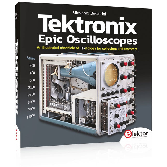
Elektor Publishing Tektronix Epic Oscilloscopes
An illustrated chronicle of Teknology for collectors and restorers Oscilloscopes have made a major contribution to the advancement of human knowledge, not only in electronics, but in all sciences, whenever a physical quantity can be converted into a timerelated electrical signal. This book traces the history of a crucial instrument through many Tektronix products. This is the company that invented and patented most of the functions found in all oscilloscopes today. Tek is and will always be synonymous with the oscilloscope. In nearly 600 pages, with hundreds of gorgeous photos, diagrams, anecdotes, and technical data, you'll travel through the history of Tektronix in a superb collector's edition with a technical point of view. The author is not afraid to get his hands dirty restoring his own Tek equipment. The journey starts in the early 1950s. It ends in the '90s, after exploring the ins and outs of the most interesting models in the 300, 400, 500, 5000, 7000, and 11000 series, from tubes to advanced hybrid technologies. Downloads NEW: Free Supplement (136 pages, 401 MB)
€ 79,95
Members € 71,96
-

Elektor Digital Analogue Video (E-book)
This book is intended for electronics enthusiasts and professionals alike, who want a much deeper understanding of the incredible technology conquests over the pre-digital decades that created video. It details evolution of analogue video electronics and technology from the first electro-mechanical television, through advancements in Cathode Ray Tubes, transistor circuits and signal processing, up to the latest analogue, colour-rich TV, entertainment devices and calibration equipment. Key technological advances that enabled monochrome video and, eventually, colour are explained. The importance, compromises and techniques of maintaining crucial backward legacy compatibilities are described. The generation, signal processing and playback of analogue video signals in numerous capture, display, recording and playback devices together with operating principles and practices are examined. Technical and, often, political merits and deficiencies of key national and international video standards are highlighted. Several formats are shown to win and ultimately to co-exist. This book begins at fairly basic levels; concepts are introduced with human physiological perceptions of light and colour explained. This leads to the subject matter of luminance and chrominance; their equations and the circuits to process. There is full, detailed analysis of waveform shapes and timings inside video equipment and relevant popular connections e.g. S-video. Several analogue video projects which you can build yourself are also included in this book; with schematics, circuit board layouts and calibration steps to help you obtain the best results. The book makes use of many colour pages where the subject matter demands it (e.g. test cards). If you really want a deeper understanding of analogue video then this book is for you!
€ 24,95
Members € 19,96
-
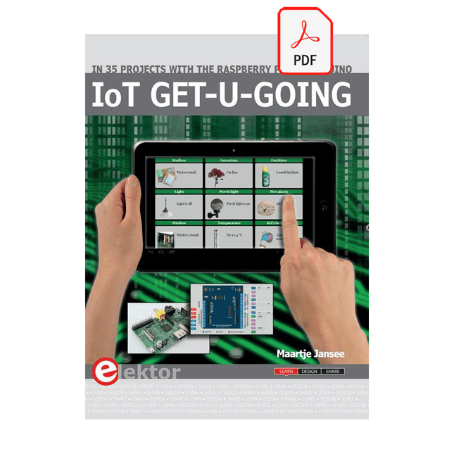
Elektor Digital IoT GET-U-GOING (E-book)
In 35 Projects with the Raspberry Pi and Arduino The Internet of Things (IoT) is a trend with a strong technological impulse. At home, we want to do everything on our tablets, from browsing Facebook to watching TV, from operating lights to keeping an eye on the temperature. In 35 fun projects, this book will show you how to build your own Internet of Things system. We'll cover the hardware (primarily the Raspberry Pi and Arduino) and the software that makes control via Internet possible. We employ Wi-Fi and radio links so no requirement any longer to install cabling crisscross through your home. Assuming the projects in the book are finished, you have a complete Internet of Things system that allows you to control and view of everything in your home. For example, if there's something in the mail box or the car is securely in the garage. Also, you can switch on the lights and the alarm from your couch. The crisp explanations allow the projects to be customized with ease, for example, to turn on your coffee machine or TV remotely. The index gives easy access to creative projects that can serve as an example, enabling you to do all the connecting to the IoT independently. All project software can be downloaded free of charge from the Elektor website. In this unique book, Raspberry Pi, Arduino and HTML webpages with stylesheets and JavaScript come together in clearly-described, easy-to-build projects. This special book is an essential part of your collection!
€ 34,95
Members € 27,96
-
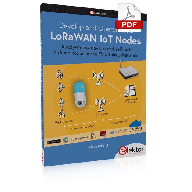
Elektor Digital Develop and Operate Your LoRaWAN IoT Nodes (E-book)
Ready-to-use devices and self-built Arduino nodes in the 'The Things Network' LoRaWAN has developed excellently as a communication solution in the IoT. The Things Network (TTN) has contributed to this. The Things Network was upgraded to The Things Stack Community Edition (TTS (CE)). The TTN V2 clusters were closed towards the end of 2021. This book shows you the necessary steps to operate LoRaWAN nodes using TTS (CE) and maybe extend the network of gateways with an own gateway. Meanwhile, there are even LoRaWAN gateways suitable for mobile use with which you can connect to the TTN server via your cell phone. The author presents several commercial LoRaWAN nodes and new, low-cost and battery-powered hardware for building autonomous LoRaWAN nodes. Registering LoRaWAN nodes and gateways in the TTS (CE), providing the collected data via MQTT and visualization via Node-RED, Cayenne, Thingspeak, and Datacake enable complex IoT projects and completely new applications at very low cost. This book will enable you to provide and visualize data collected with battery-powered sensors (LoRaWAN nodes) wirelessly on the Internet. You will learn the basics for smart city and IoT applications that enable, for example, the measurement of air quality, water levels, snow depths, the determination of free parking spaces (smart parking), and the intelligent control of street lighting (smart lighting), among others.
€ 32,95
Members € 26,36


