Search results for "mendocino OR motor OR ar OR o OR 8"
-
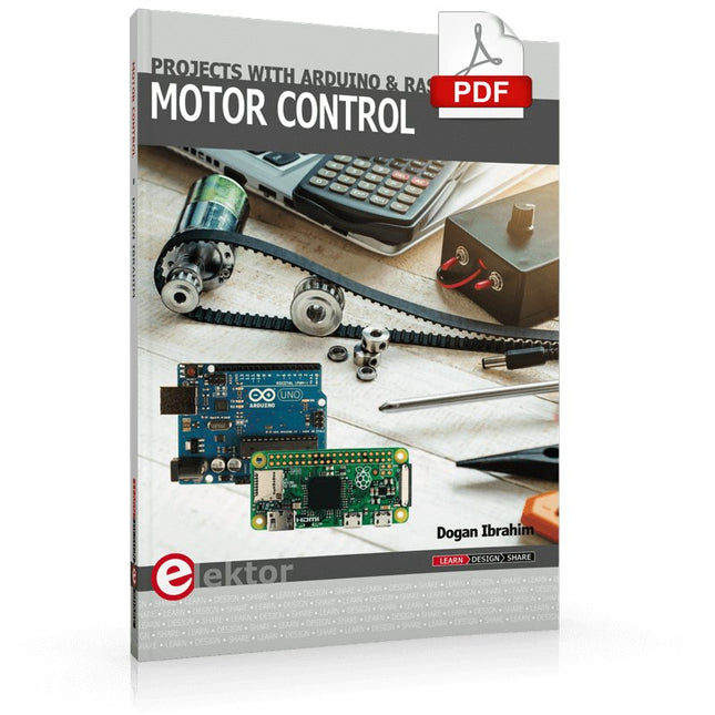
Elektor Digital Motor Control - Projects with Arduino & Raspberry Pi (E-book)
This book is about DC electric motors and their use in Arduino and Raspberry Pi Zero W based projects. The book includes many tested and working projects where each project has the following sub-headings: Title of the project Description of the project Block diagram Circuit diagram Project assembly Complete program listing of the project Full description of the program The projects in the book cover the standard DC motors, stepper motors, servo motors, and mobile robots. The book is aimed at students, hobbyists, and anyone else interested in developing microcontroller based projects using the Arduino Uno or the Raspberry Pi Zero W. One of the nice features of this book is that it gives complete projects for remote control of a mobile robot from a mobile phone, using the Arduino Uno as well as the Raspberry Pi Zero W development boards. These projects are developed using Wi-Fi as well as the Bluetooth connectivity with the mobile phone. Readers should be able to move a robot forward, reverse, turn left, or turn right by sending simple commands from a mobile phone. Full program listings of all the projects as well as the detailed program descriptions are given in the book. Users should be able to use the projects as they are presented, or modify them to suit to their own needs.
€ 29,95
Members: € 23,96
-

Elektor Digital Power Electronics in Motor Drives (E-book)
This book is for people who want to understand how AC drives (also known as inverter drives) work and how they are used in industry by showing mainly the practical design and application of drives. The key principles of power electronics are described and presented in a simple way, as are the basics of both DC and AC motors. The different parts of an AC drive are explained, together with the theoretical background and the practical design issues such as cooling and protection. An important part of the book gives details of the features and functions often found in AC drives and gives practical advice on how and where to use these. Also described is future drive technology, including a matrix inverter. The mathematics is kept to an essential minimum. Some basic understanding of mechanical and electrical theory is presumed, and a basic knowledge of single andthree phase AC systems would be useful. Anyone who uses or installs drives, or is just interested in how these powerful electronic products operate and control modern industry, will find this book fascinating and informative.
€ 29,95
Members: € 23,96
-
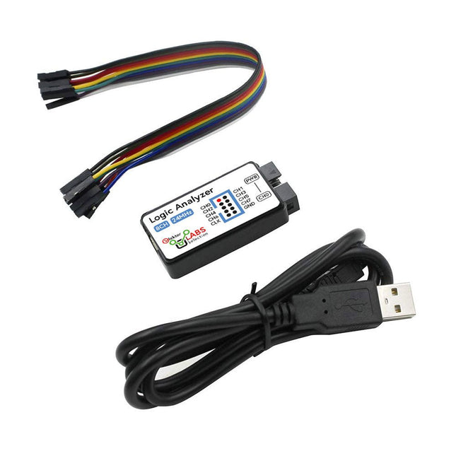
Elektor Labs USB Logic Analyzer (8-ch, 24 MHz)
This USB Logic Analyzer is an 8-channel logic analyzer with each input dual purposed for analog data recording. It is perfect for debugging and analyzing signals like I²C, UART, SPI, CAN and 1-Wire. It operates by sampling a digital input connected to a device under test (DUT) at a high sample rate. The connection to the PC is via USB. Specifications Channels 8 digital channels Maximum sampling rate 24 MHz Maximum input voltage 0~5 V Operating temperature 0~70°C Input impedance 1 MΩ || 10 pF Supported protocols I²C, SPI, UART, CAN, 1-Wire, etc. PC connection USB Dimensions 55 x 28 x 14 mm Included USB Logic Analyzer (8-ch, 24 MHz) USB Cable Jumper Wire Ribbon Cable Downloads Software
€ 14,95
Members: € 13,46
-

Elektor Digital Arduino 8-bit Sound Generation (E-book)
Arduinonext is an initiative powered by an electronics and microcontrollers specialist team aiming to help all those who are entering in the technology world, using the well-known Arduino platform to take the next step in electronics. We strive to bring you the necessary knowledge and experience for developing your own electronics applications; interacting with environment; measuring physical parameters; processing them and performing the necessary control actions. This is the first title in the 'Hands-On' series in which Arduino platform co-founder, David Cuartielles, introduces board programming, and demonstrates the making of an 8-bit Sound Generator.
€ 7,95
Members: € 6,36
-

JOY-iT Joy-Pi Advanced Development Platform (incl. Raspberry Pi 4, 8 GB)
For a limited time, the Joy-Pi Advanced is available in a great-value bundle with a Raspberry Pi 4 (8 GB)! The Joy-Pi Advanced is a compact and powerful device that allows you to realize your projects quickly and easily. Whether you already have a lot of experience, or next to none, the Joy-Pi Advanced lets you unleash your creativity. Thanks to its compatibility with a wide range of platforms, including Raspberry Pi, Raspberry Pi Pico, Arduino Nano, BBC micro:bit, and NodeMCU ESP32, you can easily and quickly access your preferred platform. In addition, the Joy-Pi Advanced features more than 30 stations, lessons, and modules, giving you an unlimited variety of ways to get your projects done. With the self-developed learning center, you can not only improve your skills but also create new projects. The learning center offers a wealth of information and tutorials that will guide you step by step through your projects. Joy-Pi Advanced is characterized in particular by its intelligent switch units, which allow an extended use of the available pins. A total of three switch units are integrated, each equipped with 12 individual switches that provide precise control of the connected sensors and modules. This system solves the well-known problem of limited pin count that occurs with conventional microcontrollers. The switch units allow you to operate a large number of sensors and modules in parallel by switching them on and off individually. This simulates multiple pin assignment, allowing you to exploit the full power of your projects without compromising functionality. By combining innovative adapter boards and the micro:bit slot, you can achieve seamless compatibility with a wide range of microcontrollers such as Raspberry Pi Pico, NodeMCU ESP32, micro:mit and Arduino Nano. The specially developed adapter boards are designed to perfectly match the respective microcontroller. By plugging the microcontroller onto the appropriate adapter board and then plugging it into the micro:bit slot, the Joy-Pi Advanced quickly and easily becomes compatible with the different microcontrollers. This allows seamless integration of your preferred platform and the ability to combine the strengths of the different microcontrollers in your projects. This way, you can fully focus on your creative projects without worrying about the compatibility of different microcontrollers. The Joy-Pi Advanced simplifies the development process and gives you the possibility to design your projects flexibly and individually. Features Highly integrated development platform & learning center Fast, easy & wireless combination of various sensors & actuators Installation option for Raspberry Pi 4 Compatible with various microcontrollers Self-developed, didactic learning platform for Raspberry Pi & Windows Specifications Compatible to Raspberry Pi 4, Arduino Nano, NodeMCU ESP32, BBC micro:bit, Raspberry Pi Pico Installed sensors, actuators & components 39 Learning platform Over 40 entries in the know-ledge database, 10 projects, 10 learning tasks, 14 visions Displays 7-segment display, 16x2 display, 1.8“ TFT display, 0.96" OLED display, 8x8 RGB matrix Sensors DS18B20, shock sensor, hall sensor, barometer, sound sensor, gyroscope, PIR sensor, Light barrier, NTC, Light sensor, 6x touch sensor, color sensor, ultrasonic distance sensor, DHT11 temperature & humidity sensor Control Joystick, 5x switches, potentiometer, rotary encoder, 4x4 button matrix, relays, PWM fan Motors Servo interface, Stepper motor interface, Vibration motor Measuring & conversion modules Analog-Digital Converter, Level converter, voltmeter, Variable voltage supply Other components RTC real time clock, buzzer, EEPROM memory, infrared receiver, breadboard, RFID reader Adapter boards Adapter for NodeMCU ESP32, Arduino Nano & Raspberry Pi Pico, Board connectors for Raspberry Pi & External Boards Electronic components Infrared remote control, RFID chip, RFID card, 6x alligator clips, microSD card reader, servo motor, stepper motor, 32 GB microSD card Components 40x resistors, 3x green LEDs, 3x yellow LEDs, 3x red LEDs, 1x transistor, 5x buttons, 1x potentiometer, 2x capacitors Other accessories Screw assortment, screwdriver, accessory storage bag, power supply & power cable, servo mount Power supply Built-in power supply: 36 W, 12 V, 3 A Case connector: Small device plug C8 Voltage outputs 12 V, 5 V, 3.3 V, Variable voltage output (2-11 V) Data buses & signal outputs I²C, SPI, Analog to digital converter Battery (RTC) CR2032 Dimensions 327 x 200 x 52 mm Included Raspberry Pi 4 (8 GB RAM) Downloads Joy-Pi website Datasheet Manual
€ 519,00€ 419,00
Best Price
-
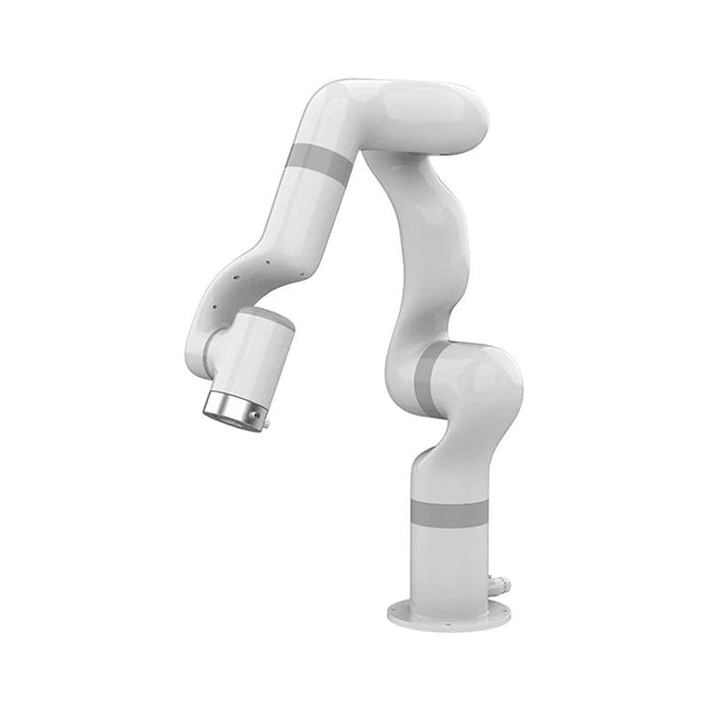
UFactory UFactory 850 Robotic Arm
UFactory 850 is the most powerful robot with industrial grade performance. Features 6DoF Payload: 5 kg Reach: 850 mm Repeatability: 0.02 mm Weight: 20 kg Applications Glambot Welding Screwdriving Robot Vision Industrial Production Designed for both mobile platforms and your workbench The AC control box contains an AC-DC adapter inside, 100-240 V AC is all ready to go. The DC control box supports 48-72 V wide inputs, it perfectly fits the battery system on your mobile platform. Flexible Deployment With Safe Feature Hand teaching, space-saving and easy to re-deploy to multiple applications without changing your production layout. Perfectly for recurrent tasks. Collision detection is available for all of our cobots. Your safety is always the top priority. Graphical Interface For Beginner-Friendly Programming Compatible with various operation systems, including macOS and Windows. Web-based technology compatible with all major browsers. Drag and drop to create your code in minutes. Powerful And Open Source SDK At Your Fingertips Fully functional open-source Python/C++ SDK provides more flexible programming. ROS/ROS2 packages are ready-to-go. Example codes help you to deploy the robotic arm smoothly. Specifications UFactory 850 xArm 5 xArm 6 xArm 7 Payload 5 kg 3 kg 5 kg 3.5 kg Reach 850 mm 700 mm 700 mm 700 mm Degrees of freedom 6 5 6 7 Repeatability ±0.02 mm ±0.1 mm ±0.1 mm ±0.1 mm Maximum Speed 1 m/s 1 m/s 1 m/s 1 m/s Weight (robot arm only) 20 kg 11.2 kg 12.2 kg 13.7 kg Maximum Speed 180°/s 180°/s 180°/s 180°/s Joint 1 ±360° ±360° ±360° ±360° Joint 2 -132°~132° -118°~120° -118°~120° -118°~120° Joint 3 -242°~3.5° -225°~11° -225°~11° ±360° Joint 4 ±360° -97°~180° ±360° -11°~225° Joint 5 -124°~124° ±360° -97°~180° ±360° Joint 6 ±360° ±360° -97°~180° Joint 7 ±360° Hardware Ambient Temperature Range 0-50°C Power Consumption Typical 240 W, max 1000 W Input Power Supply 48 V DC, 20.8 A Footprint Ø 190 mm Materials Aluminum, Carbon Fiber Base Connector Type M8x4 ISO Class Cleanroom 5 Robot Mounting Any End Effector Communication Protocol Modbus RTU End Effector I/O 2x DI / 2x DO / 2x AI / 1x RS485 Communication Mode Ethernet Included 1x UFactory 850 robotic arm 1x AC control box 1x Control box power cable
€ 11.779,00
Best Price
-

Holybro Holybro X500 V2 ARF Drone Kit
The X500 V2 ARF Kit is an affordable, lightweight, and robust carbon fiber professional drone kit that is easy to assemble (less than 15 minutes). It comes with the X500 V2 Frame Kit and motors, ESCs, power distribution boards and propellers preinstalled. It is perfectly compatible with various flight controllers such as the Holybro Pixhawk series, Durandal, Pix32 V5, etc. There are numerous improvements compared the previous model. Specifications Wheelbase: 500 mm Motor mount pattern: 16x16 mm Frame body: 144x144 mm, 2 mm thick Landing gear height: 215 mm Space between top and bottom plates: 28 mm Weight: 610 g Flight time: ~18 minutes hover with no additional payload. Tested with 5000 mAh battery. Payload: 1500 g (without battery, 70% throttle) Battery recommendation: 4S 3000-5000 mAh 20C+ with XT60 Lipo battery (not Included) Included X500 V2 Frame Kit With Preinstalled Items: 4x Motors: Holybro 2216 KV920 Motor (4 pcs) with XT30 Plug 4x ESCs (BLHeli S ESC 20A) 6x 1045 Propellers Power Distribution Board – XT60 plug for battery & XT30 plug for ESCs & peripherals Note: Depth camera mount is sold separately.
€ 379,95
Best Price
-
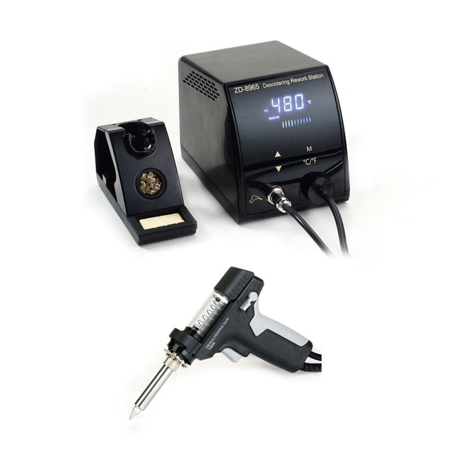
Zhongdi ZD-8965 Desoldering Station
The ZD-8965 is a digital temperature-controlled desoldering station equipped with ground protection and an LCD screen for temperature display. Despite its compact and robust design, this high-power desoldering station is easy to operate with just one hand. The ZD-8965 features a soldering gun with an integrated filter that captures any extracted material, allowing for continuous operation by simply replacing the filters. Additionally, a temperature sensor is embedded in the tip, enabling rapid response to temperature fluctuations for consistent performance. Features Effortlessly adjust the temperature between 160°C and 480°C using the convenient up/down buttons on the front panel. LED display to indicate the temperature in °C/°F Features an ergonomic pistol grip with a trigger for quick and efficient solder waste removal. The upgraded soldering gun includes a rear trigger, making it exceptionally convenient for replacing and cleaning components. Comes with a high-quality soldering gun and a sturdy holder. Equipped with a heavy-duty heater that ensures optimal desoldering performance every time. Specifications Station Voltage supply 220-240 V Power 140 W Vakuum pressure 600 mm HG Desoldering Gun Power 140 W (18 V DC)Heat up rating: 140 W Temperature 160-480°C (320-896°F) Heating element Ceramic heater Included 1x ZD-8965 Desoldering station 2x Spare soldering tips 3x Cleaning needles for desoldering tips 3x Spare filter for desoldering gun 1x Spare filter for desoldering station 1x Manual
€ 99,00
-

Zhongdi ZD-8962B ESD Soldering Station (70 W)
The ZD-8962B soldering station features an adjustable temperature range of 160°C to 480°C with an output power of 70 W. Equipped with an integrated heating element in the soldering tip, the station reaches the desired operating temperature in just 8 seconds. A large digital display provides real-time monitoring, showing both the preset target and the actual temperature of the iron for precision control. Additionally, the station is ESD-safe, ensuring sensitive electronic components are fully protected from electrostatic discharge during use. Specifications Power 70 W Input voltage 220-240 V AC/50 Hz Output voltage 20 V Temperature range 160°C – 480°C (320°F – 896°F) Heating time ~8 s Display Large, two-line LED display for showing target and actual temperature Special features ESD protection, Sleep mode/energy-saving function, Switch between °C and °F Included ZD-8962B Soldering station unit Soldering iron Soldering tip N12-1 Soldering iron stand with copper brush and sponge Soldering wire stand with lead-free soldering wire (10 g) Power cable (EU) Manual
€ 69,95€ 59,95
Best Price


-
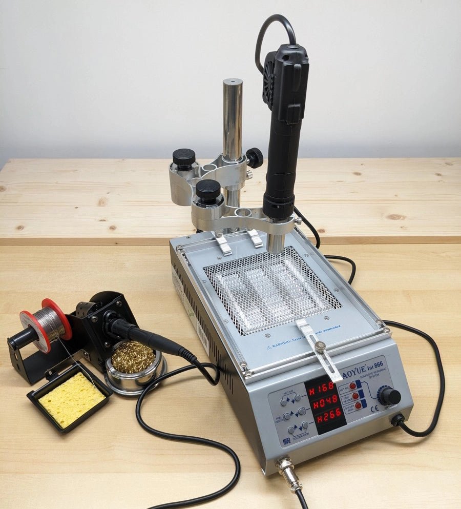
, by Jean-François Simon Mastering Electronics: An In-Depth Look at the Aoyue Int 866 Rework Station
In the ever-evolving world of electronics, soldering remains a crucial skill. Addressing this need, the Aoyue 866 rework station steps up with a multifunctional approach,...
-
, by Mathias Claussen Review: 2-in-1 SMD Hot Air Rework Station (ZD-8922)
The ZD-8922 2-in-1 SMD Hot Air Rework Station is a tool that makes soldering less of a hassle – especially if you are dealing with...
-

, by Jean-François Simon The RC-RICK-868-EV Wireless Modem: A Compelling Addition to Your Workbench
In this review, we're exploring the RC-RICK-868-EV, a specialized evaluation kit by Radiocontrolli designed for their RC-RICK-868 radio modem. This device stands out by employing...


