Search results for "lego OR rpi OR board OR 159010 OR 91"
-
Elektor Publishing Nucleo Boards Programming with the STM32CubeIDE
Hands-on in more than 50 projects STM32 Nucleo family of processors are manufactured by STMicroelectronics. These are low-cost ARM microcontroller development boards. This book is about developing projects using the popular STM32CubeIDE software with the Nucleo-L476RG development board. In the early Chapters of the book the architecture of the Nucleo family is briefly described. The book covers many projects using most features of the Nucleo-L476RG development board where the full software listings for the STM32CubeIDE are given for each project together with extensive descriptions. The projects range from simple flashing LEDs to more complex projects using modules, devices, and libraries such as GPIO, ADC, DAC, I²C, SPI, LCD, DMA, analogue inputs, power management, X-CUBE-MEMS1 library, DEBUGGING, and others. In addition, several projects are given using the popular Nucleo Expansion Boards. These Expansion Boards plug on top of the Nucleo development boards and provide sensors, relays, accelerometers, gyroscopes, Wi-Fi, and many others. Using an expansion board together with the X-CUBE-MEMS1 library simplifies the task of project development considerably. All the projects in the book have been tested and are working. The following sub-headings are given for each project: Project Title, Description, Aim, Block Diagram, Circuit Diagram, and Program Listing for the STM32CubeIDE. In this book you will learn about STM32 microcontroller architecture; the Nucleo-L476RG development board in projects using the STM32CubeIDE integrated software development tool; external and internal interrupts and DMA; DEBUG, a program developed using the STM32CubeIDE; the MCU in Sleep, Stop, and in Standby modes; Nucleo Expansion Boards with the Nucleo development boards. What you need a PC with Internet connection and a USB port; STM32CubeIDE software (available at STMicroelectronics website free of charge) the project source files, available from the book’s webpage hosted by Elektor; Nucleo-L476RG development board; simple electronic devices such as LEDs, temperature sensor, I²C and SPI chips, and a few more; Nucleo Expansion Boards (optional).
€ 49,95
Members: € 44,96
-
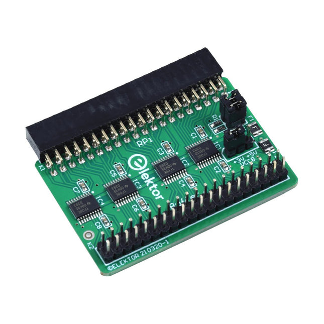
Elektor Labs Elektor Raspberry Pi Buffer Board
When you experiment with the Raspberry Pi on a regular basis and you connect a variety of external hardware to the GPIO port via the header you may well have caused some damage in the past. The Elektor Raspberry Pi Buffer Board is there to prevent this! The board is compatible with Raspberry Pi Zero, Zero 2 (W), 3, 4, 5, 400 and 500. All 26 GPIOs are buffered with bi-directional voltage translators to protect the Raspberry Pi when experimenting with new circuits. The PCB is intended to be inserted in the back of Raspberry Pi 400/500. The connector to connect to the Raspberry Pi is a right angled 40-way receptacle (2x20). The PCB is only a fraction wider. A 40-way flat cable with appropriate 2x20 headers can be connected to the buffer output header to experiment for instance with a circuit on a breadboard or PCB. The circuit uses 4x TXS0108E ICs by Texas Instruments. The PCB can also be put upright on a Raspberry Pi. Downloads Schematics Layout
€ 34,95€ 29,95
Best Price
-

Pinecone Pinecone BL602 Evaluation Board
Features Build in USB to Serial interface Build-in PCB antenna Powered by Pineseed BL602 SoC using Pinenut model: 12S stamp 2 MB Flash USB-C connection Suitable to breadboard BIY project On board three color LEDs output Dimensions: 25.4 x 44.0 mm Note: USB cable is not included.
€ 8,95€ 3,50
Best Price
-

Elektor Digital Programming with STM32 Nucleo Boards (E-book)
STM32 Nucleo family of processors are manufactured by STMicroelectronics. These are low-cost ARM microcontroller development boards. This book is about developing projects using the popular Nucleo development board. In the early chapters of the book, the architecture of the Nucleo family is briefly described. Software development tools that can be used with the Nucleo boards such as the Mbed, Keil MDK, TrueSTUDIO, and the System Workbench are described briefly in later Chapters. The book covers many projects using most features of the STM32 Nucleo development boards where the full software listings for Mbed and System Workbench are given for every project. The projects range from simple flashing LEDs to more complex projects using modules and devices such as GPIO, ADC, DAC, I²C, LCD, analog inputs and others. In addition, several projects are given using the Nucleo Expansion Boards, including popular expansion boards such as solid-state relay, MEMS and environmental sensors, DC motor driver, Wi-Fi, and stepper motor driver. These Expansion Boards plug on top of the Nucleo development boards and simplify the task of project development considerably. Features of this book Learn the architecture of the STM32 microcontrollers Learn how to use the Nucleo development board in projects using Mbed and System Workbench Toolchains Learn how to use the Nucleo Expansion Boards with the Nucleo development boards Update The Mbed compiler has been replaced with two software packages: The Mbed Studio and Keil Studio Cloud. Both of these software packages are free of charge and are available on the Internet. If you need assistance using the Keil Studio Cloud, please download the Guide below.
€ 34,95
Members: € 27,96
-
Elektor Publishing H0W2: Get Started with the MAX78000FTHR Development Board
Build your own AI microcontroller applications from scratch The MAX78000FTHR from Maxim Integrated is a small development board based on the MAX78000 MCU. The main usage of this board is in artificial intelligence applications (AI) which generally require large amounts of processing power and memory. It marries an Arm Cortex-M4 processor with a floating-point unit (FPU), convolutional neural network (CNN) accelerator, and RISC-V core into a single device. It is designed for ultra-low power consumption, making it ideal for many portable AI-based applications. This book is project-based and aims to teach the basic features of the MAX78000FTHR. It demonstrates how it can be used in various classical and AI-based projects. Each project is described in detail and complete program listings are provided. Readers should be able to use the projects as they are, or modify them to suit their applications. This book covers the following features of the MAX78000FTHR microcontroller development board: Onboard LEDs and buttons External LEDs and buttons Using analog-to-digital converters I²C projects SPI projects UART projects External interrupts and timer interrupts Using the onboard microphone Using the onboard camera Convolutional Neural Network
€ 39,95
Members: € 35,96
-

Elektor Digital H0W2: Get Started with the MAX78000FTHR Development Board (E-book)
Build your own AI microcontroller applications from scratch The MAX78000FTHR from Maxim Integrated is a small development board based on the MAX78000 MCU. The main usage of this board is in artificial intelligence applications (AI) which generally require large amounts of processing power and memory. It marries an Arm Cortex-M4 processor with a floating-point unit (FPU), convolutional neural network (CNN) accelerator, and RISC-V core into a single device. It is designed for ultra-low power consumption, making it ideal for many portable AI-based applications. This book is project-based and aims to teach the basic features of the MAX78000FTHR. It demonstrates how it can be used in various classical and AI-based projects. Each project is described in detail and complete program listings are provided. Readers should be able to use the projects as they are, or modify them to suit their applications. This book covers the following features of the MAX78000FTHR microcontroller development board: Onboard LEDs and buttons External LEDs and buttons Using analog-to-digital converters I²C projects SPI projects UART projects External interrupts and timer interrupts Using the onboard microphone Using the onboard camera Convolutional Neural Network
€ 32,95
Members: € 26,36
-

Elektor Digital Nucleo Boards Programming with the STM32CubeIDE (E-book)
Hands-on in more than 50 projects STM32 Nucleo family of processors are manufactured by STMicroelectronics. These are low-cost ARM microcontroller development boards. This book is about developing projects using the popular STM32CubeIDE software with the Nucleo-L476RG development board. In the early Chapters of the book the architecture of the Nucleo family is briefly described. The book covers many projects using most features of the Nucleo-L476RG development board where the full software listings for the STM32CubeIDE are given for each project together with extensive descriptions. The projects range from simple flashing LEDs to more complex projects using modules, devices, and libraries such as GPIO, ADC, DAC, I²C, SPI, LCD, DMA, analogue inputs, power management, X-CUBE-MEMS1 library, DEBUGGING, and others. In addition, several projects are given using the popular Nucleo Expansion Boards. These Expansion Boards plug on top of the Nucleo development boards and provide sensors, relays, accelerometers, gyroscopes, Wi-Fi, and many others. Using an expansion board together with the X-CUBE-MEMS1 library simplifies the task of project development considerably. All the projects in the book have been tested and are working. The following sub-headings are given for each project: Project Title, Description, Aim, Block Diagram, Circuit Diagram, and Program Listing for the STM32CubeIDE. In this book you will learn about STM32 microcontroller architecture; the Nucleo-L476RG development board in projects using the STM32CubeIDE integrated software development tool; external and internal interrupts and DMA; DEBUG, a program developed using the STM32CubeIDE; the MCU in Sleep, Stop, and in Standby modes; Nucleo Expansion Boards with the Nucleo development boards. What you need a PC with Internet connection and a USB port; STM32CubeIDE software (available at STMicroelectronics website free of charge) the project source files, available from the book’s webpage hosted by Elektor; Nucleo-L476RG development board; simple electronic devices such as LEDs, temperature sensor, I²C and SPI chips, and a few more; Nucleo Expansion Boards (optional).
€ 39,95
Members: € 31,96
-

Elektor Labs Elektor Arduino Nano MCCAB Training Board
The Elektor Arduino Nano MCCAB Training Board contains all the components (incl. Arduino Nano) required for the exercises in the "Microcontrollers Hands-on Course for Arduino Starters", such as light-emitting diodes, switches, pushbuttons, acoustic signal transmitters, etc. External sensors, motors or assemblies can also be queried or controlled with this microcontroller training system. Specifications (Arduino Nano MCCAB Training Board) Power Supply Via the USB connection of the connected PC or an external power supply unit (not included) Operating Voltage +5 Vcc Input Voltage All inputs 0 V to +5 V VX1 and VX2 +8 V to +12 V (only when using an external power supply) Hardware periphery LCD 2x16 characters Potentiometer P1 & P2 JP3: selection of operating voltage of P1 & P2 Distributor SV4: Distributor for the operating voltagesSV5, SV6: Distributor for the inputs/outputs of the microcontroller Switches and buttons RESET button on the Arduino Nano module 6x pushbutton switches K1 ... K6 6x slide switches S1 ... S6 JP2: Connection of the switches with the inputs of the microcontroller Buzzer Piezo buzzer Buzzer1 with jumper on JP6 Indicator lights 11 x LED: Status indicator for the inputs/outputs LED L on the Arduino Nano module, connected to GPIO D13 JP6: Connection of LEDs LD10 ... LD20 with GPIOs D2 ... D12 Serial interfacesSPI & I²C JP4: Selection of the signal at pin X of the SPI connector SV12 SV9 to SV12: SPI interface (3.3 V/5 V) or I²C interface Switching output for external devices SV1, SV7: Switching output (maximum +24 V/160 mA, externally supplied) SV2: 2x13 pins for connection of external modules 3x3 LED matrix(9 red LEDs) SV3: Columns of the 3x3 LED matrix (outputs D6 ... D8) JP1: Connection of the rows with the GPIOs D3 ... D5 Software Library MCCABLib Control of hardware components (switches, buttons, LEDs, 3x3 LED matrix, buzzer) on the MCCAB Training Board Operating Temperature Up to +40 °C Dimensions 100 x 100 x 20 mm Specifications (Arduino Nano) Microcontroller ATmega328P Architecture AVR Operating Voltage 5 V Flash Memory 32 KB, of which 2 KB used by bootloader SRAM 2 KB Clock Speed 16 MHz Analog IN Pins 8 EEPROM 1 KB DC Current per I/O Pins 40 mA on one I/O pin, total maximum 200 mA on all pins together Input Voltage 7-12 V Digital I/O Pins 22 (6 of which are PWM) PWM Output 6 Power Consumption 19 mA Dimensions 18 x 45 mm Weight 7 g Included 1x Elektor Arduino Nano Training Board MCCAB 1x Arduino Nano
€ 79,95
Members: € 71,96


-
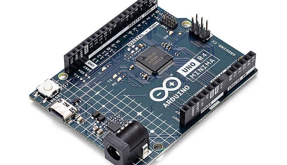
, by Clemens Valens Two New Arduino UNO R4 Boards: Minima and WiFi
The Arduino UNO R4 Minima and the Arduino UNO R4 WiFi have finally hit the shelves, introducing an exciting new chapter for Arduino enthusiasts and...
-
, by Lobna Belarbi Must-Have Boards, Kits & Tools to Start Your Arduino Journey with Elektor
Whether you're a newcomer eager to explore the world of microcontrollers or an experienced maker seeking to expand your toolkit, Elektor offers a curated selection...
-
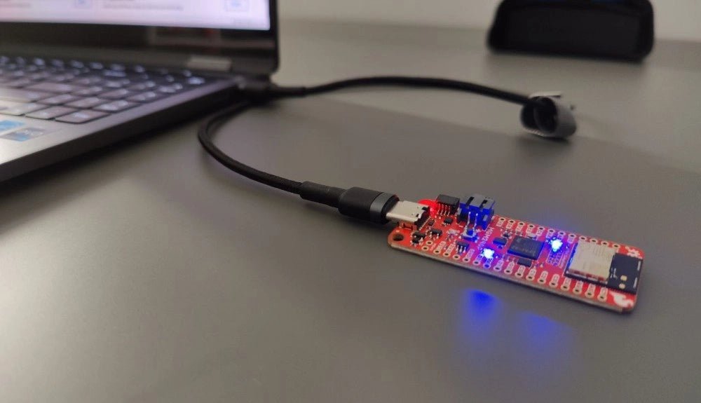
, by Saad Imtiaz SparkFun Thing Plus Matter (MGM240P): A Versatile Matter-Based IoT Development Board (Review)
The SparkFun Thing Plus Matter (MGM240P) is a versatile and feature-rich development board designed for creating Matter-based IoT devices. Matter, formerly known as Project CHIP...
-
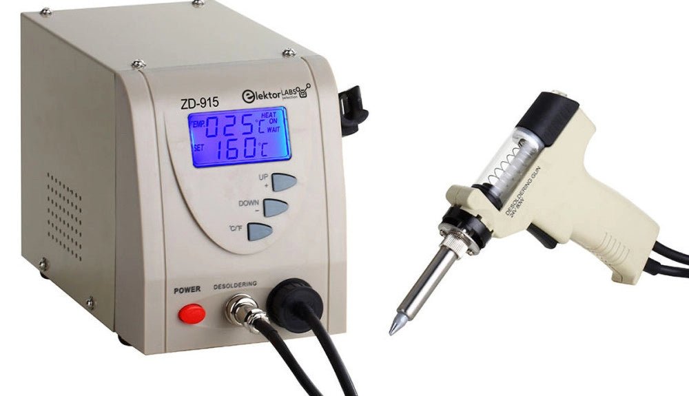
, by Harry Baggen Review: ZD-915 Desoldering Station
Soldering a circuit together is usually a fun and rewarding job, but desoldering components on an (old) printed circuit board takes a bit more effort,...


