Search results for "laserclock OR based OR on OR sand OR clock OR kit OR of OR parts"
-
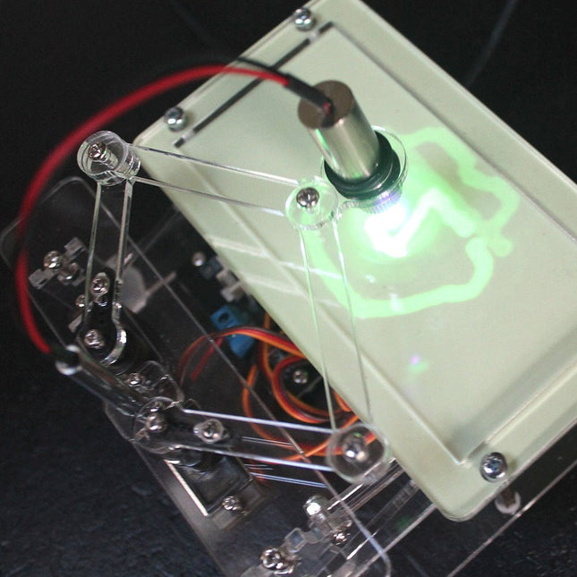
Elektor Labs Elektor Laser Head Upgrade for Sand Clock
The Elektor Laser Head transforms the Elektor Sand Clock into a clock that writes the time on glow-in-the-dark film instead of sand. In addition to displaying the time, it can also be used to create ephemeral drawings. The 5 mW laser pointer, with a wavelength of 405 nm, produces bright green drawings on the glow-in-the-dark film. For best results, use the kit in a dimly lit room. Warning: Never look directly into the laser beam! The kit includes all the necessary components, but soldering three wires is required. Note: This kit is also compatible with the original Arduino-based Sand Clock from 2017. For more details, see Elektor Magazine 1-2/2017 and Elektor Magazine 1-2/2018.
€ 34,95€ 24,95
Best Price
-
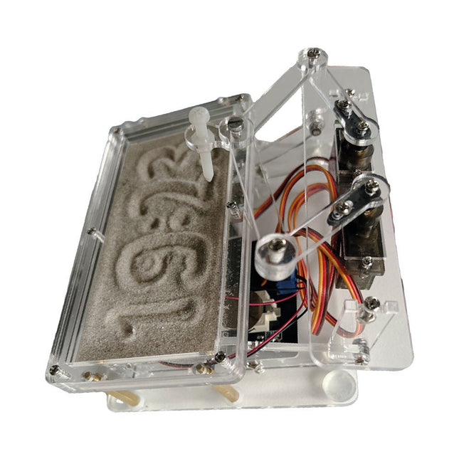
Elektor Labs Elektor Sand Clock for Raspberry Pi Pico
Raspberry Pi-based Eye Catcher A standard sand clock just shows how time passes. In contrast, this Raspberry Pi Pico-controlled sand clock shows the exact time by “engraving” the four digits for hour and minute into the layer of sand. After an adjustable time the sand is flattened out by two vibration motors and everything begins all over again. At the heart of the sand clock are two servo motors driving a writing pen through a pantograph mechanism. A third servo motor lifts the pen up and down. The sand container is equipped with two vibration motors to flatten the sand. The electronic part of the sand clock consists of a Raspberry Pi Pico and an RTC/driver board with a real-time clock, plus driver circuits for the servo motors. A detailed construction manual is available for downloading. Features Dimensions: 135 x 110 x 80 mm Build time: approx. 1.5 to 2 hours Included 3x Precut acrylic sheets with all mechanical parts 3x Mini servo motors 2x Vibration motors 1x Raspberry Pi Pico 1x RTC/driver board with assembled parts Nuts, bolts, spacers, and wires for the assembly Fine-grained white sand
€ 49,95€ 39,95
Best Price
-

Elektor Digital Linux PC-based Measurement Electronics (E-book)
This book is intended as a highly-practical guide for Hobbyists, Engineers and Scientists wishing to build measurement and control systems to be controlled by a local or remote Personal Computer running the Linux operating system. Both hardware and software aspects of designing typical embedded systems are covered in detail with schematics, code listings and full descriptions. Numerous examples have been designed to show clearly how straightforward it can be to create the interfaces between digital and analog electronics, with programming techniques for creating control software for both local and remote systems. Hardware developers will appreciate the variety of circuits, including a novel, low cost modulated wireless link and will discover how using Matlab® overcomes the need for specialist programming skills. Software developers will appreciate how a better understanding of circuits plus the freedom offered by Linux to directly control at the register level enables them to optimize related programs. There is no need to buy special equipment or expensive software tools in order to create embedded projects covered in this book. You can build such quality systems quickly using popular low-cost electronic components and free distributed or low-cost software tools. Some knowledge of basic electronics plus the very basics of C programming only is required. Many projects in this book are developed using Matlab® being a very popular worldwide computational tool for research in engineering and science. The book provides a detailed description of how to combine the power of Matlab® with practical electronics. With an emphasis on learning by doing, readers are encouraged by examples to program with ease; the book provides clear guidelines as to the appropriate programming techniques “on the fly”. Complete and well-documented source code is provided for all projects. If you want to learn how to quickly build Linux-based applications able to collect, process and display data on a PC from various analog and digital sensors, how to control circuitry attached to a computer, then even how to pass data via a network or control your embedded system wirelessly and more – then this is the book for you! Features of this Book Use the power, flexibility and control offered only by a Linux operating system on a PC. Use a free, distributed downloadable GNU C compiler Use (optional) a low-cost Student Version of Matlab®. Use low-cost electronic sub-assemblies for projects. Improve your skills in electronics, programming, networking and wireless design. A full chapter is dedicated to controlling your sound card for audio input and output purposes. Program sound using OSS and ALSA. Learn how to combine electronic circuits, software, networks and wireless technologies in the complete embedded system.
€ 29,95
Members: € 23,96
-

Elektor Labs Elektor Sand Clock for Raspberry Pi Pico (incl. Laser Head Upgrade)
This bundle contains the popular Elektor Sand Clock for Raspberry Pi Pico and the new Elektor Laser Head Upgrade, offering even more options for displaying the time. Not only can you "engrave" the current time in sand, you can now alternatively write it on a glow-in-the-dark foil or create green drawings. Contents of the bundle Elektor Sand Clock for Raspberry Pi Pico (normal price: €50) Elektor Laser Head Upgrade for Sand Clock (normal price: €35) Elektor Sand Clock for Raspberry Pi (Raspberry Pi-based Eye Catcher) A standard sand clock just shows how time passes. In contrast, this Raspberry Pi Pico-controlled sand clock shows the exact time by "engraving" the four digits for hour and minute into the layer of sand. After an adjustable time the sand is flattened out by two vibration motors and everything begins all over again. At the heart of the sand clock are two servo motors driving a writing pen through a pantograph mechanism. A third servo motor lifts the pen up and down. The sand container is equipped with two vibration motors to flatten the sand. The electronic part of the sand clock consists of a Raspberry Pi Pico and an RTC/driver board with a real-time clock, plus driver circuits for the servo motors. A detailed construction manual is available for downloading. Features Dimensions: 135 x 110 x 80 mm Build time: approx. 1.5 to 2 hours Included 3x Precut acrylic sheets with all mechanical parts 3x Mini servo motors 2x Vibration motors 1x Raspberry Pi Pico 1x RTC/driver board with assembled parts Nuts, bolts, spacers, and wires for the assembly Fine-grained white sand Elektor Laser Head Upgrade for Sand Clock The new Elektor Laser Head transforms the Sand Clock into a clock that writes the time on glow-in-the-dark film instead of sand. In addition to displaying the time, it can also be used to create ephemeral drawings. The 5 mW laser pointer, with a wavelength of 405 nm, produces bright green drawings on the glow-in-the-dark film. For best results, use the kit in a dimly lit room. Warning: Never look directly into the laser beam! The kit includes all the necessary components, but soldering three wires is required. Note: This kit is also compatible with the original Arduino-based Sand Clock from 2017. For more details, see Elektor Magazine 1-2/2017 and Elektor Magazine 1-2/2018.
€ 84,95€ 69,95
Best Price
-
Elektor Publishing PID-based Practical Digital Control with Raspberry Pi and Arduino Uno
The Arduino Uno is an open-source microcontroller development system encompassing hardware, an Integrated Development Environment (IDE), and a vast number of libraries. It is supported by an enormous community of programmers, electronic engineers, enthusiasts, and academics. The libraries in particular really smooth Arduino programming and reduce programming time. What’s more, the libraries greatly facilitate testing your programs since most come fully tested and working. The Raspberry Pi 4 can be used in many applications such as audio and video media devices. It also works in industrial controllers, robotics, games, and in many domestic and commercial applications. The Raspberry Pi 4 also offers Wi-Fi and Bluetooth capability which makes it great for remote and Internet-based control and monitoring applications. This book is about using both the Raspberry Pi 4 and the Arduino Uno in PID-based automatic control applications. The book starts with basic theory of the control systems and feedback control. Working and tested projects are given for controlling real-life systems using PID controllers. The open-loop step time response, tuning the PID parameters, and the closed-loop time response of the developed systems are discussed together with the block diagrams, circuit diagrams, PID controller algorithms, and the full program listings for both the Raspberry Pi and the Arduino Uno. The projects given in the book aim to teach the theory and applications of PID controllers and can be modified easily as desired for other applications. The projects given for the Raspberry Pi 4 should work with all other models of Raspberry Pi family. The book covers the following topics: Open-loop and closed-loop control systems Analog and digital sensors Transfer functions and continuous-time systems First-order and second-order system time responses Discrete-time digital systems Continuous-time PID controllers Discrete-time PID controllers ON-OFF temperature control with Raspberry Pi and Arduino Uno PID-based temperature control with Raspberry Pi and Arduino Uno PID-based DC motor control with Raspberry Pi and Arduino Uno PID-based water level control with Raspberry Pi and Arduino Uno PID-based LED-LDR brightness control with Raspberry Pi and Arduino Uno
€ 39,95
Members: € 35,96
-
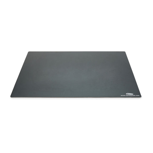
Sensepeek Sensepeek 4021 Insulated XL Base Plate
Components are both shrinking and getting increasingly finer pitch year after year but your PCBs might have grown in size or the number of interconnected PCBs or the number of handsfree PCBite probes needed to test your design may have increased making it crowded on our other smaller base plates. Features With a size of 297 x 420 mm (DIN A3) the extra large baseplate has room for most PCBs and many handsfree PCBite probes for those measurements sessions where more channels than available is needed. So if you are looking for more space, extra protection or just want to clean up your work surface then this accessory is a perfect match. Designed to be used with Sensepeeks magnetic PCBite line of products including PCB holders, hands free probes and magnifier. Included 1x XL base plate (DIN A3) with pre-fitted insulation cover
€ 71,39
-

Elektor Labs Elektor AM Transmitter Kit
Build Your Own Vintage Radio Broadcaster The Elektor AM Transmitter Kit allows streaming audio to vintage AM radio receivers. Based on a Raspberry Pi Pico microcontroller module, the AM Transmitter can transmit on 32 frequencies in the AM band, from 500 kHz up to 1.6 MHz in 32 steps of approx. 35 kHz. The frequency is selected with a potentiometer and shown on a 0.96" OLED display. A pushbutton allows toggles the transmitting mode between On and Off. The range of the transmitter depends on the antenna. The onboard antenna provides a range of a few centimeters, requiring the AM Transmitter to be placed close to or inside the radio. An external loop antenna (not included) can be connected to increase the range. The Elektor AM Transmitter Kit comes as a kit of parts that you must solder to the board yourself. Features The board is compatible with a Hammond 1593N enclosure (not included).A 5 VDC power supply with micro-USB connector (e.g., an old phone charger) is needed to power the kit (not included). Current consumption is 100 mA. The Arduino software (requiring Earle Philhower’s RP2040 Boards Package) for the Elektor AM Transmitter Kit plus more information is available at the Elektor Labs page of this project. Component List Resistors R1, R4 = 100 Ω R2, R3, R8 = 10 kΩ R5, R6, R9, R10, R11 = 1 kΩ R7 = optional (not included) P1 = potentiometer 100 kΩ, linear Capacitors C1 = 22 µF 16V C2, C4 = 10 nF C3 = 150 pF Miscellaneous K1 = 4×1 pin socket K2, K3 = 3.5 mm socket Raspberry Pi Pico pushbutton, angle mount 0.96" monochrome I²C OLED display PCB 150292-1
€ 34,95€ 29,95
Best Price
-

iFixit iFixit Manta Driver Kit
This kit includes iFixit's widest assortment of bits, complete with every driver head you’ll need to tackle any repair or DIY project. It includes standard bits like Phillips and Flathead in a full range of sizes to handle everything from precision electronics repair to home DIY projects. And it wouldn’t be an iFixit bit set if it didn’t include all the exotic bits from Pentalobes for Apple iPhone and MacBook repair to Gamebits for your vintage Nintendo consoles. All of the next-gen bit sets have been re-designed in order to maximize convenience and usability. The bit set lid is held in place with magnets to increase product lifespan (no more broken hinges or clasps) and also mounts to the back of the bit set case to keep it out of the way while you do your work. If you need help keeping your screws and parts organized, you can use the lid’s integrated sorting tray. The 4 mm bits have been adjusted and have now a longer neck for a deeper and more precise reach. Toolkit Includes Easy-to-Open Magnetized Case Lid with Built-in Sorting Tray 4 mm Aluminum Bit Driver 1/4' Aluminum Bit Driver 4 mm Screwdriver Bits Phillips - 000, 00, 0 Flathead - 1, 1.5, 2, 2.5, 3, 3.5 mm Torx - T2, T3, T4, T5 Torx Security - TR6, TR7, TR8 Pentalobe - P2, P5, P6 JIS - 000, 00, 0, 1 Hex - 0.7, 0.9, 1.3, 1.5 mm Hex Security - 2, 2.5, 3, 3.5 mm Tri-point - Y000, Y00, Y0, Y1 Nut driver - 2.5, 3, 3.5, 4, 4.5, 5, 5.5 mm Gamebit - 3.8, 4.5 mm Spanner - 4, 6 Triangle - 2, 2.2, 2.6, 3 mm Oval Bit iPhone Standoff Bit Sim Eject Bit Magnetic Pickup Bit 1/4' Screwdriver Bits Phillips - 1, 2, 3 Flathead - 4, 5, 6, 7, 8 mm Hex Security - 4, 5, 6, 7, 8 mm Hex Security SAE - 1/8, 9/64, 5/32, 3/16, 7/32, 1/4 Pozidriv - PZ0, PZ1, PZ2, PZ3 Torq-set - 6, 8, 10 Spanner - 8, 10, 12 Square - 0, 1, 2, 3 Spline - M5, M6, M8 Torx Security - TR9, TR10, TR15, TR20, TR25, TR27, TR30, TR35, TR40 Tri-wing 1, 2, 3, 4 Clutch 1, 2, 3 Schrader Valve Hook Drive 1/4' to 4 mm Adapter 1/4' Driver to 1/4' Socket 1/4' Driver to 3/8' Socket 1/4' Socket to 1/4' Driver Specifications Bit Metal: 6150 Steel Driver Material: Anodized Aluminum Case Material: ABS Foam: EVA
€ 64,95


-
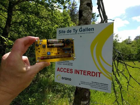
, by Clemens Valens Review: Detect Radiation with the MightyOhm Geiger Counter Kit
The MightyOhm Geiger Counter is a device for detecting beta and gamma radiation levels. Because radiation is so harmful, you may want to keep an...
-
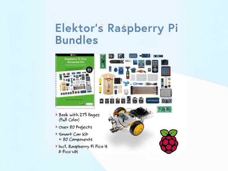
, by Lobna Belarbi Elektor’s Raspberry Pi Bundles: From Beginner-Friendly to Advanced Kits
Find the Perfect Raspberry Pi Bundle for Your Skill Level Whether you're a beginner eager to explore the world of Raspberry Pi or an advanced...
-
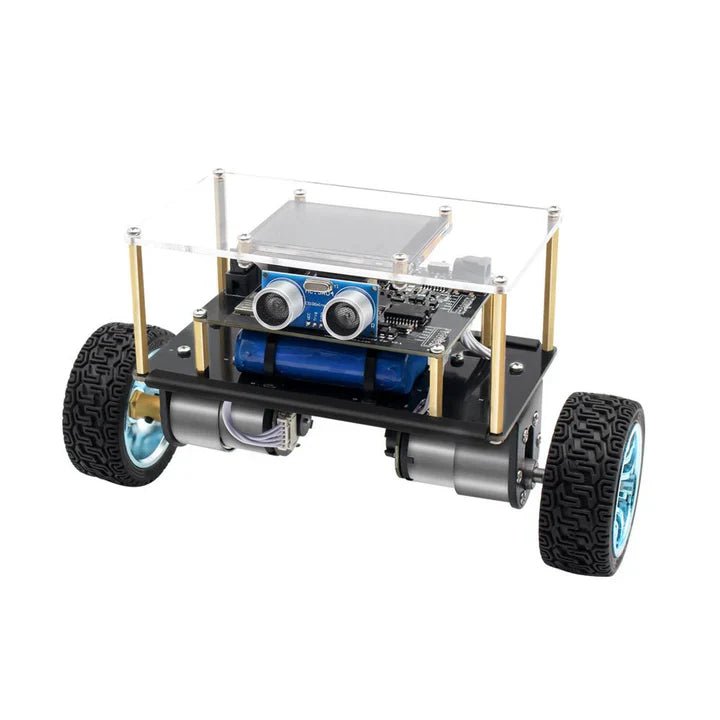
, by Lobna Belarbi Affordable Robot Kits to Kickstart Your Robotics Journey
Robotics is an exciting and rewarding field, but getting started can be intimidating—especially when it comes to choosing the right kit. Fortunately, Elektor offers a...
-

, by Lobna Belarbi Must-Have Boards, Kits & Tools to Start Your Arduino Journey with Elektor
Whether you're a newcomer eager to explore the world of microcontrollers or an experienced maker seeking to expand your toolkit, Elektor offers a curated selection...


