Search results for "inside OR an OR open OR source OR processor"
-

Elektor Digital Inside an Open-Source Processor (E-book)
An Introduction to RISC-V RISC-V is an Instruction Set Architecture (ISA) that is both free and open. This means that the RISC-V ISA itself does not require a licensing fee, although individual implementations may do so. The RISC-V ISA is curated by a non-profit foundation with no commercial interest in products or services that use it, and it is possible for anyone to submit contributions to the RISC-V specifications. The RISC-V ISA is suitable for applications ranging from embedded microcontrollers to supercomputers. This book will first describe the 32-bit RISC-V ISA, including both the base instruction set as well as the majority of the currently-defined extensions. The book will then describe, in detail, an open-source implementation of the ISA that is intended for embedded control applications. This implementation includes the base instruction set as well as a number of standard extensions. After the description of the CPU design is complete the design is expanded to include memory and some simple I/O. The resulting microcontroller will then be implemented in an affordable FPGA development board (available from Elektor) along with a simple software application so that the reader can investigate the finished design.
€ 32,95
Members: € 26,36
-

Electron Plus Electron Plus SPA100 Source Picoammeter
This highly sensitive source picoammeter is designed for measuring and logging very small currents down to the pA range – making it an ideal instrument for scientific and research applications, including physics, materials science and electron microscopy. Full-featured at an affordable price, the SPA100 combines sensitivity, accuracy and stability to allow users to measure low currents with high precision as well as conveniently source bias voltages for experimentation. SPA100 also doubles as an ultra-high resistance meter, measuring accurately into the teraohm range. The SPA100 connects to PC via USB and utilises the complimentary software SPA – enabling users to easily measure, graph and capture readings with timestamps and measurement stability information. Features Input: ±2 mA to ±200 pA in 8 ranges Accuracy and Resolution (2 Hz): ±2 mA range: ±0.1%, resolution <20 nA ±200 uA range: ±0.1%, resolution <2 nA ±20 uA range: ±0.2%, resolution <200 pA ±2 uA range: ±0.2%, resolution <20 pA ±200 nA range: ±0.5%, resolution <2 pA ±20 nA range: ±0.5%, resolution <200 fA ±2 nA range: ±1.0%, resolution <20 fA ±200 pA range: ±1.5%, resolution <2 fA Sample rate: 2 Hz (18 bit) or 10 Hz (16 bit) Adjustable filter: 1 sample to 64 samples Output voltage: -40 V to +40 V (in 1 V increments), output resistance 2.7 Kohms Resistance Measurement: ~1 Kohms to 40 Tohms (e.g 40 V source, 1 pA measure) Accuracy: >±0.5% 1 Mohm to 1 Tohm Powered via USB 2.0 (instrument uses up to 0.3 A when in-use) Included 1x SPA100 Source Picoammeter 1x USB cable Downloads Manual Software
€ 264,99
-
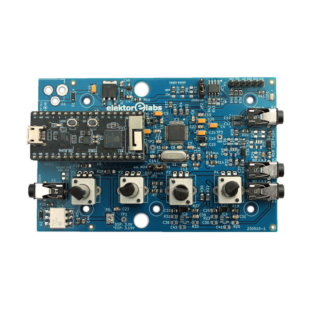
Elektor Labs Elektor Audio DSP FX Processor (New Revision)
The Elektor Audio DSP FX Processor combines an ESP32 microcontroller and an ADAU1701 Audio DSP from Analog Devices. Besides a user-programmable DSP core, the ADAU1701 has high-quality analog-to-digital and digital-to-analog converters built-in and features an I²S port. This makes it suitable as a high-quality audio interface for the ESP32. Programs for the ESP32 can be created with Arduino, Platform IO, CMake or by using the Espressif IDF in another way. Programs for the ADAU7101 audio DSPs are created with the free visual programming tool SigmaStudio by dragging and dropping pre-defined algorithm blocks on a canvas. Applications Bluetooth/Wi-Fi audio sink (e.g. loudspeaker) & source Guitar effect pedal (stomp box) Music synthesizer Sound/function generator Programmable cross-over filter for loudspeakers Advanced audio effects processor (reverb, chorus, pitch shifting, etc.) Internet-connected audio device DSP experimentation platform Wireless MIDI MIDI to CV converter and many more... Specifications ADAU1701 28-/56-bit, 50-MIPS digital audio processor supporting sampling rates of up to 192 kHz ESP32 32-bit dual-core microcontroller with Wi-Fi 802.11b/g/n and Bluetooth 4.2 BR/EDR and BLE 2x 24-bit audio inputs (2 V RMS, 20 kΩ) 4x 24-bit audio outputs (0.9 V RMS, 600 Ω) 4x Control potentiometer MIDI in- and output I²C expansion port Multi-mode operation Power supply: 5 V DC USB or 7.5-12 V DC (barrel jack, center pin is GND) Current consumption (average): 200 mA Included 1x ESP32 Audio DSP FX Processor board (assembled) 1x ESP32-PICO-KIT 2x Jumpers 2x 18-pin headers (female) 4x 10 KB potentiometers Downloads Documentation GitHub
€ 99,95€ 84,95
Best Price
-
Elektor Digital The Arduino-Inside Measurement Lab (E-book)
An 8-in-1 test & measurement instrument for the electronics workbench A well-equipped electronics lab is crammed with power supplies, measuring devices, test equipment and signal generators. Wouldn‘t it be better to have one compact device for almost all tasks? Based on the Arduino, a PC interface is to be developed that’s as versatile as possible for measurement and control. It simply hangs on a USB cable and – depending on the software – forms the measuring head of a digital voltmeter or PC oscilloscope, a signal generator, an adjustable voltage source, a frequency counter, an ohmmeter, a capacitance meter, a characteristic curve recorder, and much more. The circuits and methods collected here are not only relevant for exactly these tasks in the "MSR" electronics lab, but many details can also be used within completely different contexts.
€ 29,95
Members: € 23,96
-
Elektor Digital Red Pitaya for Test and Measurement (E-book)
The Red Pitaya (STEMlab) is a credit card-sized, open-source test and measurement board that can be used to replace most measurement instruments used in electronics laboratories. With a single click, the board can transform into a web-based oscilloscope, spectrum analyser, signal generator, LCR meter, Bode plotter, and microcontroller. The Red Pitaya (STEMlab) can replace the many pieces of expensive measurement equipment found at professional research organisations and teaching laboratories. The device, that based on Linux, includes an FPGA, digital signal processing (DSP), dual core ARM Cortex processor, signal acquisition and generation circuitry, micro USB socket, microSD card slot, RJ45 socket for Ethernet connection, and USB socket – all powered from an external mains adaptor. This book is an introduction to electronics. It aims to teach the principles and applications of basic electronics by carrying out real experiments using the Red Pitaya (STEMlab). The book includes many chapters on basic electronics and teaches the theory and use of electronic components including resistors, capacitors, inductors, diodes, transistors, and operational amplifiers in electronic circuits. Many fun and interesting Red Pitaya (STEMlab) experiments are included in the book. The book also makes an introduction to visual programming environment. The book is written for college level and first year university students studying electrical or electronic engineering.
€ 29,95
Members: € 23,96
-
Elektor Publishing FPGA Programming and Hardware Essentials
Kick off with the MAX1000 and VHDPlus Ready to Master FPGA Programming? In this guide, we’re diving into the world of Field Programmable Gate Arrays (FPGAs) – a configurable integrated circuit that can be programmed after manufacturing. Imagine bringing your ideas to life, from simple projects to complete microcontroller systems! Meet the MAX1000: a compact and budget-friendly FPGA development board packed with features like memory, user LEDs, push-buttons, and flexible I/O ports. It’s the ideal starting point for anyone wanting to learn about FPGAs and Hardware Description Languages (HDLs). In this book, you’ll get hands-on with the VHDPlus programming language – a simpler version of VHDL. We’ll work on practical projects using the MAX1000, helping you gain the skills and confidence to unleash your creativity. Get ready for an exciting journey! You’ll explore a variety of projects that highlight the true power of FPGAs. Let’s turn your ideas into reality and embark on your FPGA adventure – your journey starts now! Exciting Projects You’ll Find in This Book Arduino-Driven BCD to 7-Segment Display Decoder Use an Arduino Uno R4 to supply BCD data to the decoder, counting from 0 to 9 with a one-second delay Multiplexed 4-Digit Event Counter Create an event counter that displays the total count on a 4-digit display, incrementing with each button press PWM Waveform with Fixed Duty Cycle Generate a PWM waveform at 1 kHz with a fixed duty cycle of 50% Ultrasonic Distance Measurement Measure distances using an ultrasonic sensor, displaying the results on a 4-digit 7-segment LED Electronic Lock Build a simple electronic lock using combinational logic gates with push buttons and an LED output Temperature Sensor Monitor ambient temperature with a TMP36 sensor and display the readings on a 7-segment LED Downloads Software
€ 39,95
Members: € 35,96
-
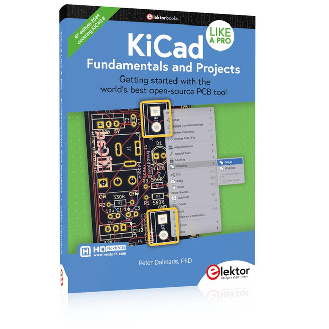
Elektor Publishing KiCad Like A Pro – Fundamentals and Projects
Getting started with the world’s best open-source PCB tool The latest iteration of KiCad, the world’s best free-to-use Printed Circuit Board tool, is packed with features usually found only in expensive commercial CAD tools. This modern, cross-platform application suite built around schematic and design editors, with auxiliary applications is a stable and mature PCB tool. KiCad 8 is a perfect fit for electronic engineers and makers. Here are the most significant improvements and features in KiCad 8, both over and under the hood: Modern user interface, completely redesigned from earlier versions Improved and customizable electrical and design rule checkers Theme editor allowing you to customize KiCad on your screen Ability to import projects from Eagle, CADSTART, and more Python scripting API Improved integrated SPICE circuit simulator Multi-sheet schematics Filters define selectable elements Enhanced interactive router helps you draw single tracks and differential pairs with precision New or enhanced tools to draw tracks, measure distances, tune track lengths, etc. Advanced interactive router Built-in bill of materials generator Realistic ray-tracing capable 3D viewer Customizable teardrops Plug-in manager for quick installation of themes, libraries and functionalities such as autorouters and BOM generators This book will teach you to use KiCad through a practical approach. It will help you become productive quickly and start designing your own boards. Example projects illustrate the basic features of KiCad, even if you have no prior knowledge of PCB design. The author describes the entire workflow from schematic entry to the intricacies of finalizing the files for PCB production and offers sound guidance on the process. Further full-fledged projects, of incremental difficulty, will be presented in a second book, together with a variety of advanced recipes.
€ 54,95
Members: € 49,46
-
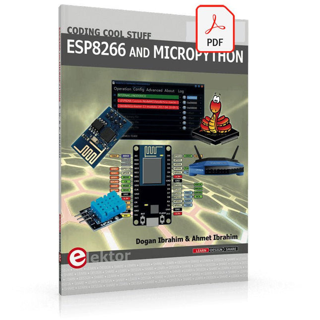
Elektor Digital ESP8266 and MicroPython (E-book)
Recently, the development of a tiny chip called the ESP8266 has made it possible to interface any type of microcontroller to a Wi-Fi AP. The ESP8266 is a low-cost tiny Wi-Fi chip having fully built-in TCP/IP stack and a 32-bit microcontroller unit. This chip, produced by Shanghai based Chinese manufacturer Espressif System, is IEEE 802.11 b/g/n Wi-Fi compatible with on-chip program and data memory, and general purpose input-output ports. Several manufacturers have incorporated the ESP8266 chip in their hardware products (e.g. ESP-xx, NodeMCU etc) and offer these products as a means of connecting a microcontroller system such as the Android, PIC microcontroller or others to a Wi-Fi. The ESP8266 is a low-power chip and costs only a few Dollars. ESP8266 and MicroPython – Coding Cool Stuff is an introduction to the ESP8266 chip and describes the features of this chip and shows how various firmware and programming languages such as the MicroPython can be uploaded to the chip. The main aim of the book is to teach the readers how to use the MicroPython programming language on ESP8266 based hardware, especially on the NodeMCU. Several interesting and useful projects are given in the e-book (pdf) to show how to use the MicroPython in NodeMCU type ESP8266 hardware: Project “What shall I wear today?”: You will be developing a weather information system using a NodeMCU development board together with a Text-to-Speech processor module. Project “The Temperature and Humidity on the Cloud”: You will be developing a system that will get the ambient temperature and humidity using a sensor and then store this data on the cloud so that it can be accessed from anywhere. Project “Remote Web Based Control”: You will be developing a system that will remotely control two LEDs connected to a NodeMCU development board using an HTTP Web Server application.
€ 29,95
Members: € 23,96
-
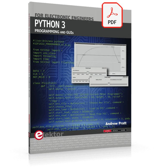
Elektor Digital Python 3 Programming and GUIs (E-book)
This is the second edition of a book aimed at engineers, scientists, and hobbyists who want to interface PCs with hardware projects using graphical user interfaces. Desktop and web-based applications are covered. The programming language used is Python 3, which is one of the most popular languages around: speed of programming being a key feature. The book has been revised and updated with an emphasis on getting the user to produce practical designs with ease – a text editor is all that is required to produce Python programs. Hardware interfacing is achieved using an Arduino Uno as a remote slave. A full description and source code of the communication interface is given in the book. The slave provides digital and analog input and outputs. Multiple Unos can be included in one project with all control code written in Python and running on a PC One project involves a PIC microcontroller with the code provided that can be loaded into the PIC using the Uno. The web applications and server are all implemented in Python, allowing you to access your electronic hardware over the Internet. The Raspberry Pi computer can be used as your web server. An introductory chapter is provided to get you started with using Linux. The book is written for use with Debian or variations including Mint or Ubuntu. All of the programs in the book are freely available, ready to use and experiment with by way of a download from Elektor.
€ 29,95
Members: € 23,96
-
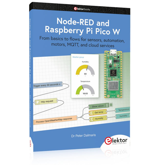
Elektor Publishing Node-RED and Raspberry Pi Pico W
From basics to flows for sensors, automation, motors, MQTT, and cloud services This book is a learning guide and a reference. Use it to learn Node-RED, Raspberry Pi Pico W, and MicroPython, and add these state-of-the-art tools to your technology toolkit. It will introduce you to virtual machines, Docker, and MySQL in support of IoT projects based on Node-RED and the Raspberry Pi Pico W. This book combines several elements into a platform that powers the development of modern Internet of Things applications. These elements are a flow-based server, a WiFi-enabled microcontroller, a high-level programming language, and a deployment technology. Combining these elements gives you the tools you need to create automation systems at any scale. From home automation to industrial automation, this book will help you get started. Node-RED is an open-source flow-based development tool that makes it easy to wire together devices, APIs, and online services. Drag and drop nodes to create a flowchart that turns on your lights at sunset or sends you an email when a sensor detects movement. Raspberry Pi Pico W is a version of the Raspberry Pi Pico with added 802.11n Wi-Fi capability. It is an ideal device for physical computing tasks and an excellent match to the Node-RED. Quick book facts Project-based learning approach. Assumes no prior knowledge of flow-based programming tools. Learn to use essential infrastructure tools in your projects, such as virtual machines, Docker, MySQL and useful web APIs such as Google Sheets and OpenWeatherMap. Dozens of mini-projects supported by photographs, wiring schematics, and source code. Get these from the book GitHub repository. Step-by-step instructions on everything. All experiments are based on the Raspberry Pi Pico W. A Wi-Fi network is required for all projects. Hardware (including the Raspberry Pi Pico W) is available as a kit. Downloads GitHub
€ 49,95
Members: € 44,96
-

Elektor Publishing Automotive Sensors and Actuators
Principles, Systems, and Electronics This handbook provides a detailed study of the sensors and actuators at the heart of modern vehicle electronics. It begins with basic electrical and electronic concepts, introducing the principles and terminology essential for understanding automotive systems. The book explores sensors and actuators on a system-by-system basis, including: Fundamentals of electrical engineering, electromagnetic phenomena, and motor principles Passive and active electronic components, integrated circuits, protection devices, and automotive-grade electronics Sensor characteristics, signal conditioning, ADCs, PWM and frequency outputs, and interface adaptation Automotive communication links and protocols, including LIN and SENT Engine sensors: air mass, pressure, temperature, speed, position, exhaust and emissions-related sensors Transmission sensors for manual and automatic systems Steering and suspension sensors for conventional and active systems Vehicle body and electrical system sensors for comfort, climate, access, and monitoring functions Engine actuators such as throttle bodies, injectors, turbo actuators, EGR systems, ignition components, and pumps Transmission, brake, steering, suspension, and body actuators Identification and coding of electronic components and packages commonly used in automotive applications The structure and operating principles of each component are explained, with relevant electronic circuitry illustrated. Its system-oriented organization and practical focus make it a valuable reference for understanding, testing, and troubleshooting automotive electronic systems.
€ 39,95
Members: € 35,96


-
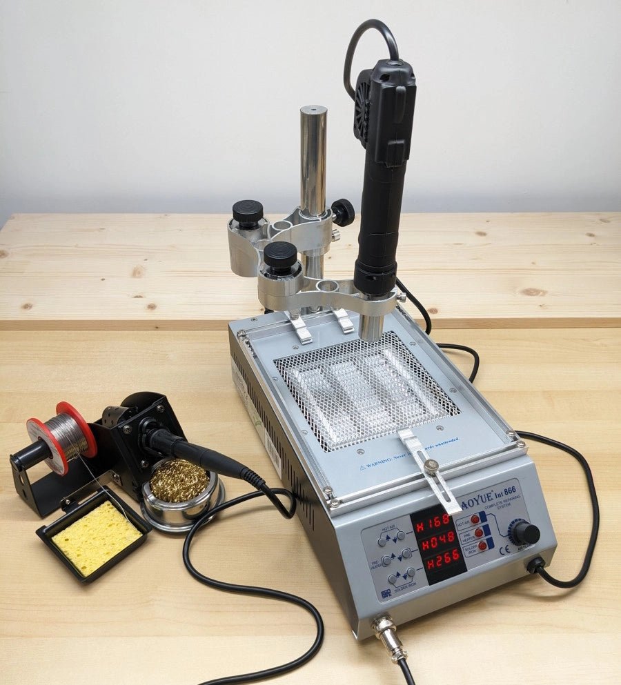
, by Jean-François Simon Mastering Electronics: An In-Depth Look at the Aoyue Int 866 Rework Station
In the ever-evolving world of electronics, soldering remains a crucial skill. Addressing this need, the Aoyue 866 rework station steps up with a multifunctional approach,...
