Search results for "hc OR sr501 OR pir OR motion OR sensor OR module"
-

Würth Abc of Power Modules (E-book)
Functionality, structure and handling of a power module For readers with first steps in power management the “Abc of Power Modules” contains the basic principles necessary for the selection and use of a power module. The book describes the technical relationships and parameters related to power modules and the basis for calculation and measurement techniques. Contents Basics This chapter describes the need of a DC/DC voltage converter and its basic functionality. Furthermore, various possibilities for realizing a voltage regulator are presented and the essential advantages of a power module are mentioned. Circuit topologies Circuit concepts, buck and boost topologies very frequently used with power modules are explained in detail and further circuit topologies are introduced. Technology, construction and regulation technology The mechanical construction of a power module is presented, which has a significant influence on EMC and thermal performance. Furthermore, control methods are explained and circuit design tips are provided in this chapter. Measuring methods Meaningful measurement results are absolutely necessary to assess a power module. The relevant measurement points and measurement methods are described in this chapter. Handling The aspects of storage and handling of power modules are explained, as well as their manufacturing and soldering processes. Selection of a power modules Important parameters and criteria for the optimal selection of a power module are presented in this section.
€ 8,99
Members: € 7,19
-

Elektor Publishing Automotive Sensors and Actuators
Principles, Systems, and Electronics This handbook provides a detailed study of the sensors and actuators at the heart of modern vehicle electronics. It begins with basic electrical and electronic concepts, introducing the principles and terminology essential for understanding automotive systems. The book explores sensors and actuators on a system-by-system basis, including: Fundamentals of electrical engineering, electromagnetic phenomena, and motor principles Passive and active electronic components, integrated circuits, protection devices, and automotive-grade electronics Sensor characteristics, signal conditioning, ADCs, PWM and frequency outputs, and interface adaptation Automotive communication links and protocols, including LIN and SENT Engine sensors: air mass, pressure, temperature, speed, position, exhaust and emissions-related sensors Transmission sensors for manual and automatic systems Steering and suspension sensors for conventional and active systems Vehicle body and electrical system sensors for comfort, climate, access, and monitoring functions Engine actuators such as throttle bodies, injectors, turbo actuators, EGR systems, ignition components, and pumps Transmission, brake, steering, suspension, and body actuators Identification and coding of electronic components and packages commonly used in automotive applications The structure and operating principles of each component are explained, with relevant electronic circuitry illustrated. Its system-oriented organization and practical focus make it a valuable reference for understanding, testing, and troubleshooting automotive electronic systems.
€ 39,95
Members: € 35,96
-
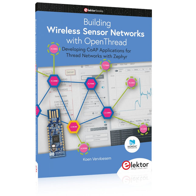
Elektor Publishing Building Wireless Sensor Networks with OpenThread
Developing CoAP applications for Thread networks with Zephyr This book will guide you through the operation of Thread, the setup of a Thread network, and the creation of your own Zephyr-based OpenThread applications to use it. You’ll acquire knowledge on: The capture of network packets on Thread networks using Wireshark and the nRF Sniffer for 802.15.4. Network simulation with the OpenThread Network Simulator. Connecting a Thread network to a non-Thread network using a Thread Border Router. The basics of Thread networking, including device roles and types, as well as the diverse types of unicast and multicast IPv6 addresses used in a Thread network. The mechanisms behind network discovery, DNS queries, NAT64, and multicast addresses. The process of joining a Thread network using network commissioning. CoAP servers and clients and their OpenThread API. Service registration and discovery. Securing CoAP messages with DTLS, using a pre-shared key or X.509 certificates. Investigating and optimizing a Thread device’s power consumption. Once you‘ve set up a Thread network with some devices and tried connecting and disconnecting them, you’ll have gained a good insight into the functionality of a Thread network, including its self-healing capabilities. After you’ve experimented with all code examples in this book, you’ll also have gained useful programming experience using the OpenThread API and CoAP.
€ 39,95
Members: € 35,96
-
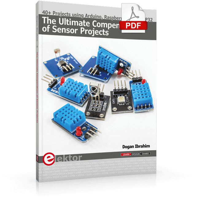
Elektor Digital The Ultimate Compendium of Sensor Projects (E-book)
40+ Projects using Arduino, Raspberry Pi and ESP32 This book is about developing projects using the sensor-modules with Arduino Uno, Raspberry Pi and ESP32 microcontroller development systems. More than 40 different sensors types are used in various projects in the book. The book explains in simple terms and with tested and fully working example projects, how to use the sensors in your project. The projects provided in the book include the following: Changing LED brightness RGB LEDs Creating rainbow colours Magic wand Silent door alarm Dark sensor with relay Secret key Magic light cup Decoding commercial IR handsets Controlling TV channels with IT sensors Target shooting detector Shock time duration measurement Ultrasonic reverse parking Toggle lights by clapping hands Playing melody Measuring magnetic field strength Joystick musical instrument Line tracking Displaying temperature Temperature ON/OFF control Mobile phone-based Wi-Fi projects Mobile phone-based Bluetooth projects Sending data to the Cloud The projects have been organized with increasing levels of difficulty. Readers are encouraged to tackle the projects in the order given. A specially prepared sensor kit is available from Elektor. With the help of this hardware, it should be easy and fun to build the projects in this book.
€ 34,95
Members: € 27,96
-

Elektor Digital Automotive Sensors and Actuators (E-book)
Principles, Systems, and Electronics This handbook provides a detailed study of the sensors and actuators at the heart of modern vehicle electronics. It begins with basic electrical and electronic concepts, introducing the principles and terminology essential for understanding automotive systems. The book explores sensors and actuators on a system-by-system basis, including: Fundamentals of electrical engineering, electromagnetic phenomena, and motor principles Passive and active electronic components, integrated circuits, protection devices, and automotive-grade electronics Sensor characteristics, signal conditioning, ADCs, PWM and frequency outputs, and interface adaptation Automotive communication links and protocols, including LIN and SENT Engine sensors: air mass, pressure, temperature, speed, position, exhaust and emissions-related sensors Transmission sensors for manual and automatic systems Steering and suspension sensors for conventional and active systems Vehicle body and electrical system sensors for comfort, climate, access, and monitoring functions Engine actuators such as throttle bodies, injectors, turbo actuators, EGR systems, ignition components, and pumps Transmission, brake, steering, suspension, and body actuators Identification and coding of electronic components and packages commonly used in automotive applications The structure and operating principles of each component are explained, with relevant electronic circuitry illustrated. Its system-oriented organization and practical focus make it a valuable reference for understanding, testing, and troubleshooting automotive electronic systems.
€ 32,95
Members: € 26,36
-

Elektor Special: Sensors for Weather and the Environment
Build your textbook weather station or conduct environmental research together with the whole world. With many practical projects for Arduino, Raspberry Pi, NodeMCU, ESP32, and other development boards. Weather stations have enjoyed great popularity for decades. Every current and even every long discontinued electronics magazine has regularly featured articles on building your own weather station. Over the years, they have become increasingly sophisticated and can now be fully integrated into an automated home — although this often requires loyalty to an (expensive) brand manufacturer across all components. With your own weather and environmental data, you can keep up and measure things that no commercial station can. It’s also fun: expand your knowledge of electronics, current microcontroller development boards and programming languages in a fun and meaningful way. For less than 10 euros you can get started and record your first environmental data — with time and growing interest, you will continue to expand your system. In this Edition Which Microcontroller Fits My Project? The Right Development Environment Tracking Wind and Weather Weather Display with OpenWeatherMap and Vacuum Fluorescent Display Volatile Organic Compounds in the Air We Breathe Working with MQ Sensors: Measuring Carbon Monoxide — Odorless but Toxic CO2 Traffic Light with ThingSpeak IoT Connection An Automatic Plant Watering System Good Indoor Climate: Temperature and Humidity are Important criteria Classy Thermometer with Vintage Tube Technology Nostalgic Weather House for the Whole Family Measuring Air Pressure and Temperature Accurately Sunburn Warning Device DIY Sensor for Sunshine Duration Simple Smartphone Says: Fog or Clear View? Identifying Earthquakes Liquid Level Measurement for Vessels and Reservoirs Water pH Value Measurement Detecting Radioactive Radiation GPS: Sensor Location Service Across the Globe Saving and Timestamping Log Files on SD Cards LoRaWAN, The Things Network, and ThingSpeak Operating a LoRaWAN Gateway for TTN Defying "Wind and Weather" Mega Display with Weather Forecasz
€ 19,95
Members: € 17,96
-

Elektor Digital Building Wireless Sensor Networks with OpenThread (E-book)
Developing CoAP applications for Thread networks with Zephyr This book will guide you through the operation of Thread, the setup of a Thread network, and the creation of your own Zephyr-based OpenThread applications to use it. You’ll acquire knowledge on: The capture of network packets on Thread networks using Wireshark and the nRF Sniffer for 802.15.4. Network simulation with the OpenThread Network Simulator. Connecting a Thread network to a non-Thread network using a Thread Border Router. The basics of Thread networking, including device roles and types, as well as the diverse types of unicast and multicast IPv6 addresses used in a Thread network. The mechanisms behind network discovery, DNS queries, NAT64, and multicast addresses. The process of joining a Thread network using network commissioning. CoAP servers and clients and their OpenThread API. Service registration and discovery. Securing CoAP messages with DTLS, using a pre-shared key or X.509 certificates. Investigating and optimizing a Thread device’s power consumption. Once you‘ve set up a Thread network with some devices and tried connecting and disconnecting them, you’ll have gained a good insight into the functionality of a Thread network, including its self-healing capabilities. After you’ve experimented with all code examples in this book, you’ll also have gained useful programming experience using the OpenThread API and CoAP.
€ 32,95
Members: € 26,36
-
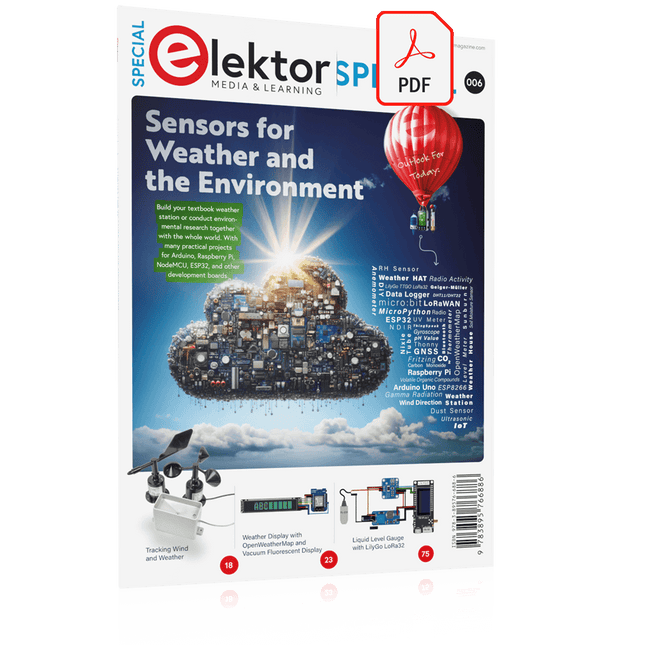
Elektor Digital Elektor Special: Sensors for Weather and the Environment (PDF)
Build your textbook weather station or conduct environmental research together with the whole world. With many practical projects for Arduino, Raspberry Pi, NodeMCU, ESP32, and other development boards. Weather stations have enjoyed great popularity for decades. Every current and even every long discontinued electronics magazine has regularly featured articles on building your own weather station. Over the years, they have become increasingly sophisticated and can now be fully integrated into an automated home — although this often requires loyalty to an (expensive) brand manufacturer across all components. With your own weather and environmental data, you can keep up and measure things that no commercial station can. It’s also fun: expand your knowledge of electronics, current microcontroller development boards and programming languages in a fun and meaningful way. For less than 10 euros you can get started and record your first environmental data — with time and growing interest, you will continue to expand your system. In this Edition Which Microcontroller Fits My Project? The Right Development Environment Tracking Wind and Weather Weather Display with OpenWeatherMap and Vacuum Fluorescent Display Volatile Organic Compounds in the Air We Breathe Working with MQ Sensors: Measuring Carbon Monoxide — Odorless but Toxic CO2 Traffic Light with ThingSpeak IoT Connection An Automatic Plant Watering System Good Indoor Climate: Temperature and Humidity are Important criteria Classy Thermometer with Vintage Tube Technology Nostalgic Weather House for the Whole Family Measuring Air Pressure and Temperature Accurately Sunburn Warning Device DIY Sensor for Sunshine Duration Simple Smartphone Says: Fog or Clear View? Identifying Earthquakes Liquid Level Measurement for Vessels and Reservoirs Water pH Value Measurement Detecting Radioactive Radiation GPS: Sensor Location Service Across the Globe Saving and Timestamping Log Files on SD Cards LoRaWAN, The Things Network, and ThingSpeak Operating a LoRaWAN Gateway for TTN Defying "Wind and Weather" Mega Display with Weather Forecasz
€ 14,95
Members: € 13,46
-

Elektor Bundles Elektor Raspberry Pi Pico Advanced Kit (Bundle)
Comprehensive Book-Hardware Bundle for the RP2040 Microcontroller with over 80 Projects Unlock the potential of modern controller technology with the Raspberry Pi Pico in this bundle. Perfect for both beginners and experienced users, the easy-to-follow guide takes you from the basics of electronics to the complexities of digital signal processing. With the Raspberry Pi Pico, the dedicated hardware kit and MicroPython programming, you will learn the key principles of circuit design, data collection, and processing. Get hands-on with over 80 projects like a stopwatch with an OLED display, a laser distance meter, and a servo-controlled fan. These projects are designed to help you apply what you've learned in real-world scenarios. The book also covers advanced topics like wireless RFID technology, object detection, and sensor integration for robotics. Whether you're looking to build your skills in electronics or dive deeper into embedded systems, this bundle is the perfect resource to help you explore the full potential of the Raspberry Pi Pico. Contents of the Bundle 1x Project Book (273 pages) 1x Raspberry Pi Pico H 1x Smart Car Kit Electronic Parts 2x Solderless breadboard (400 holes) 1x Solderless breadboard (170 holes) 5x Colorful 5 mm LEDs (green, red, blue, yellow and white) 1x Laser transmitter 1x Passive buzzer 1x Micro USB cable (30 cm) 1x 65 Jumper wires 1x 20 cm male to female Dupont wire 1x Clear case 1x Magnet (diameter: 8 mm, thickness: 5 mm) 1x Rotary potentiometer 10x 2 KΩ resistors 2x M2.5x30 mm copper pillars 10x Phillips pan head screws 10x M2.5 nickel hex nuts 1x 2-inch dual-purpose screwdriver Modules 1x RGB module 1x 9G servo 1x Dual-axis XY joystick module 1x RC522 RFID module 1x 4 Bits digital LED display module 1x Traffic light display module 1x Rotary Encoder module 1x 1602 LCD Display module (Blue) 1x Photoresistor module 1x DC motor with male Dupont wire 1x Fan blade 1x Raindrops module 1x OLED module 1x Membrane switch keyboard 1x Mini magnetic spring module 1x Infrared remote control 1x Infrared receiver module 1x DC stepper motor driver board 1x Button Sensors 1x Vibration sensor 1x Soil moisture sensor 1x Sound sensor 1x Mini PIR motion sensor 1x Temperature & Humidity sensor 1x Flame sensor 2x Crash sensor 2x Tracking sensor 1x Ultrasonic sensor
€ 99,95€ 79,95
Best Price
-

Elektor Digital Mastering the I²C Bus (E-book)
Mastering the I²C Bus takes you on an exploratory journey of the I²C Bus and its applications. Besides the Bus protocol, plenty of attention is given to the practical applications and designing a stable system. The most common I²C compatible chip classes are covered in detail. Two experimentation boards are available that allow for rapid prototype development. These boards are completed by a USB to I²C probe and a software framework to control I²C devices from your computer. All samples programs can be downloaded from the 'Attachments/Downloads' section on this page. Projects built on Board 1: USB to I²C Interface, PCA 9534 Protected Input, PCA 9534 Protected Output, PCA 9553 PWM LED Controller, 24xxx EEPROM Module, LM75 Temperature Sensor, PCA8563 Real-time Clock with Battery Backup, LCD and Keyboard Module, Bus Power Supply. Projects built on Board 2: Protected Input, Protected Output, LM75 Temperature Sensor, PCF8574 I/O Board, SAA1064 LED Display, PCA9544 Bus Expander, MCP40D17 Potentiometer, PCF8591 AD/DA, ADC121 A/D Converter, MCP4725 D/A Converter, 24xxx EEPROM Module.
€ 34,95
Members: € 27,96
-

Elektor Digital Home Automation Projects with Arduino (E-book)
Using the RFID Starter Kit An Arduino board has now become ‘the’ basic component in the maker community. No longer is an introduction to the world of microcontrollers the preserve of the expert. When it comes to expanding the capabilities of the basic Arduino board however, the developer is still largely on his own. If you really want to build some innovative projects it’s often necessary to get down to component level. This can present many beginners with major problems. That is exactly where this book begins. This book explains how a wide variety of practical projects can be built using items supplied in a single kit together with the Arduino board. This kit, called the 'RFID Starter Kit for Arduino' (SKU 17240) is not just limited to RFID applications but contains more than 30 components, devices and modules covering all areas of modern electronics. In addition to more simple components such as LEDs and resistors there are also complex and sophisticated modules that employ the latest technology such as: A humidity sensor A multicolor LED A large LED matrix with 64 points of light A 4-character 7-segment LED display An infra red remote-controller unit A complete LC-display module A servo A stepper motor and controller module A complete RFID reader module and security tag On top of that you will get to build precise digital thermometers, hygrometers, exposure meters and various alarm systems. There are also practical devices and applications such as a fully automatic rain sensor, a sound-controlled remote control system, a multifunctional weather station and so much more. All of the projects described can be built using the components supplied in the Elektor kit.
€ 29,95
Members: € 23,96


-

, by Jean-François Simon The RC-RICK-868-EV Wireless Modem: A Compelling Addition to Your Workbench
In this review, we're exploring the RC-RICK-868-EV, a specialized evaluation kit by Radiocontrolli designed for their RC-RICK-868 radio modem. This device stands out by employing...
