Functionality, structure and handling of a power module
For readers with first steps in power management the “Abc of Power Modules” contains the basic principles necessary for the selection and use of a power module. The book describes the technical relationships and parameters related to power modules and the basis for calculation and measurement techniques.
Contents
Basics
This chapter describes the need of a DC/DC voltage converter and its basic functionality. Furthermore, various possibilities for realizing a voltage regulator are presented and the essential advantages of a power module are mentioned.
Circuit topologies
Circuit concepts, buck and boost topologies very frequently used with power modules are explained in detail and further circuit topologies are introduced.
Technology, construction and regulation technology
The mechanical construction of a power module is presented, which has a significant influence on EMC and thermal performance. Furthermore, control methods are explained and circuit design tips are provided in this chapter.
Measuring methods
Meaningful measurement results are absolutely necessary to assess a power module. The relevant measurement points and measurement methods are described in this chapter.
Handling
The aspects of storage and handling of power modules are explained, as well as their manufacturing and soldering processes.
Selection of a power modules
Important parameters and criteria for the optimal selection of a power module are presented in this section.
The FNIRSI FNB58 USB tester (with Bluetooth) is a comprehensive and very accurate USB voltage and current meter. It features a 2.0-inch full-color HD TFT display, built-in USB-A, micro USB and USB-C interface. With this device you can measure the power supply or power consumption of products or the charging power of cell phones and power supplies. You can also determine the fast charging protocol of chargers.
Features
USB-A and USB-C interface
2.0" HD display
Data at a glance
Wide compatibility
Ultra-precise data detection
Play with fast charging technology
Automatic protocol detection (PD2.0, 3.0, 3.1, PPS, QC2.0, 3.0, FCP, SCP, AFC, PE, DASH VOOC, SuperVOOC and more)
Simple user interface, easy to operate
4 function curve displays (real-time voltage and current curve, offline curve recording, D+/D- voltage curve, high-speed power supply ripple measurement)
Cable detection
10 groups of energy recording battery capacity calculation
PC connectivity for data logging and firmware updates
Bluetooth app for Android devices
Specifications
Voltage range
4-28 V
Current range
0-7 A
Power range
0-120 W
Load equivalent internal resistance
0-9999.9 Ω
D+/D- voltage
0-3.3 V
Capacity
0-9999.99 Ah
Power consumption
0-9999.99 Wh
Cable resistance
0-9999.9 Ω
Interfaces
micro USB, USB-A, USB-C
Dimensions
42 x 13 x 82 mm
Downloads
Manual
Firmware V0.68
Features
Data-logger & Multimeter & Thermometer
3 (5/6) digits
True RMS test supported
BLE 4.0 wireless transmission, more stable, less power consumption
Chart and Diagram mode, to analyze your data
Supports NCV
Voice Broadcast simplifies testing
Flashlight function
Built-in offline recording function
Supports Android, iOS
Included
Test leads
K-type thermocouple
9 V Battery
Bolt driver
Crocodile clip
Quick guide
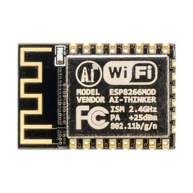
This Wi-Fi module is based on the popular ESP8266 chip. The module is FCC and CE certified and RoHS compliant.
Fully compatible with ESP-12E. 13 GPIO pins, 1 analog input, 4 MB flash memory.
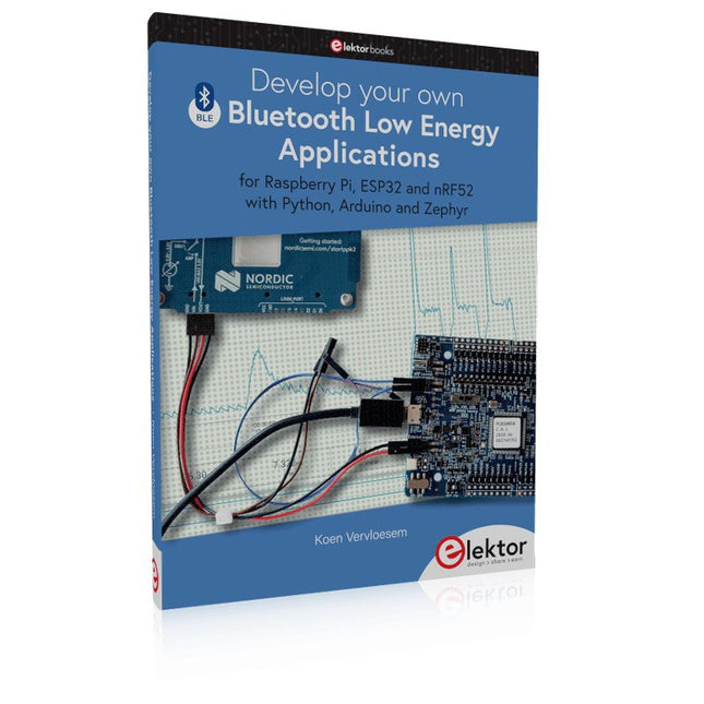
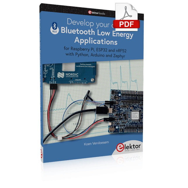
For Raspberry Pi, ESP32 and nRF52 with Python, Arduino and Zephyr
Bluetooth Low Energy (BLE) radio chips are ubiquitous from Raspberry Pi to light bulbs. BLE is an elaborate technology with a comprehensive specification, but the basics are quite accessible.
A progressive and systematic approach will lead you far in mastering this wireless communication technique, which is essential for working in low power scenarios.
In this book, you’ll learn how to:
Discover BLE devices in the neighborhood by listening to their advertisements.
Create your own BLE devices advertising data.
Connect to BLE devices such as heart rate monitors and proximity reporters.
Create secure connections to BLE devices with encryption and authentication.
Understand BLE service and profile specifications and implement them.
Reverse engineer a BLE device with a proprietary implementation and control it with your own software.
Make your BLE devices use as little power as possible.
This book shows you the ropes of BLE programming with Python and the Bleak library on a Raspberry Pi or PC, with C++ and NimBLE-Arduino on Espressif’s ESP32 development boards, and with C on one of the development boards supported by the Zephyr real-time operating system, such as Nordic Semiconductor's nRF52 boards.
Starting with a very little amount of theory, you’ll develop code right from the beginning. After you’ve completed this book, you’ll know enough to create your own BLE applications.
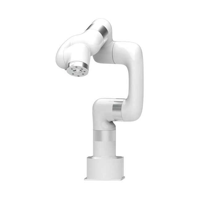
This multi-axis robot perfectly balances power and size.
Features
Payload: 5 kg
Reach: 700 mm
Repeatability: 0.1 mm
Max Speed 1000 mm/s
Applications
Machine Tending
Bin Picking
Mobile platform
Lab Automation
Robotic Research
Durable Collaborative robots for your automation
Industrial-grade harmonic drive and servomotors guarantee 24/7 working without stop.
Crafted from Carbon fiber, 15 kg weight makes it possible for easier deployment.
Flexible deployment with safe feature
Hand teaching, lightweight, space-saving and easy to re-deploy to multiple applications without changing your production layout. Perfectly for recurrent tasks.
Collision detection is available for all of our cobots. Your safety is always the top priority.
Graphical interface for beginner-friendly programming
Compatible with various of operation systems, including macOS and Windows.
Web-based technology compatible with all major browsers.
Drag and drop to create your code in minutes.
Powerful and open source SDK at your fingertips
Fully functional open-source Python/C++ SDK provides more flexible programming.
ROS/ROS2 packages are ready-to-go.
Example codes help you to deploy the robotic arm smoothly.
Specifications
UFactory 850
xArm 5
xArm 6
xArm 7
Payload
5 kg
3 kg
5 kg
3.5 kg
Reach
850 mm
700 mm
700 mm
700 mm
Degrees of freedom
6
5
6
7
Repeatability
±0.02 mm
±0.1 mm
±0.1 mm
±0.1 mm
Maximum Speed
1 m/s
1 m/s
1 m/s
1 m/s
Weight (robot arm only)
20 kg
11.2 kg
12.2 kg
13.7 kg
Maximum Speed
180°/s
180°/s
180°/s
180°/s
Joint 1
±360°
±360°
±360°
±360°
Joint 2
-132°~132°
-118°~120°
-118°~120°
-118°~120°
Joint 3
-242°~3.5°
-225°~11°
-225°~11°
±360°
Joint 4
±360°
-97°~180°
±360°
-11°~225°
Joint 5
-124°~124°
±360°
-97°~180°
±360°
Joint 6
±360°
±360°
-97°~180°
Joint 7
±360°
Hardware
xArm
Robot specs
Ambient Temperature Range
0-50°C
Power Consumption
Min 8.4 W, Typical 200 W, max 400 W
Input Power Supply
24 V DC, 16.5 A
Footprint
Ø 126 mm
Materials
Aluminum, Carbon Fiber
Base Connector Type
M5x5
ISO Class Cleanroom
5
Robot Mounting
Any
End Effector Communication Protocol
Modbus RTU(rs485)
End Effector I/O
2x DI/2x DO/2x AI/1x RS485
Communication Mode
Ethernet
Included
1x xArm 6 robotic arm
1x AC control box
1x Robotic arm power cable
1x Robotic arm end effector adapter cable
1x Robotic arm signal cable
1x Control box power cable
1x Network cable
1x Mounting tool
1x Quick start guide
This Crowtail series 4G module is a high-performance LTE Cat1 wireless module. It uses the SIM A7670E communication module from Simcom and communicates through a UART interface, which enables 4G data transmission and voice communication. The module supports multiple LTE bands, including B1/B3/B5/B7/B8/B20, as well as WCDMA and GSM networks. In addition, it supports various protocols such as TCP/IP, FTP, HTTP, and multiple satellite navigation systems such as GPS, GLONASS, and BDS.
The module comes with a charging interface and can be powered by a 3.7 V lithium battery or a 5 V USB-C interface. It also has a 3.5 mm headphone jack, and by connecting a headphone with a microphone, it can be used for making and receiving phone calls. Its compact size makes it easy to integrate into various IoT devices and meet various application requirements. Furthermore, its low power consumption and reliable performance are also the reasons why it is widely used in IoT, smart home, automotive, and industrial control fields.
Features
Integrate the A7670E communication module, enabling 4G data transmission and voice communication with low power consumption and high reliability
Supports multiple LTE bands, including B1/B3/B5/B7/B8/B20, as well as WCDMA and GSM networks
Supports various protocols such as TCP/IP, FTP, HTTP, and multiple satellite navigation systems such as GPS, GLONASS, and BDS
Comes with a charging interface and a headphone jack, which can be used for making and receiving phone calls by connecting a headphone with a microphone
Small but powerful, compact size makes it easy to integrate into various IoT devices.
Specifications
Main Chip: SIM A7670E
LTE-FDD: B1/B3/B5/B7/B8/B20
GSM: 900/1800 MHz
GSM/GPRS power class
EGSM900: 4 (33 dBm ±2 dB)
DCS1800: 1 (30 dBm ±2 dB)
EDGE power class:
EGSM900: E2 (27 dBm ±3 dB)
DCS1800 : E1 (26 dBm +3 dB/-4 dB)
LTE power class: 3 (23 dBm ±7 dB)
Supply Voltage: 4 V ~ 4.2 V
Power: 3.8 V
LTE(Mbps): 10 (DL)/5 (UL)
GPRS/EDGE(Kbps): 236.8 (DL)/236.8 (UL)
Protocol: TCP/IP/IPV4/IPV6/Multi-PDP/FTP/FTPS /HTTP/HTTPS/DNS
Communication interface: USB / UART
Firmware Upgrade: USB/FOTA
Support phonebook types: SM/FD/ON/AP/SDN
Interfaces: 1x Power button, 1x BAT, 1x UART, 1x USB-C, 1x SIM Card slot
Dimensions: 35 x 50 mm
Included
1x Crowtail-4G SIM-A7670E
1x 4G GSM NB-IoT Antenna
1x GPS ceramic antenna
Downloads
Wiki
A7670 AT Command Manual
A7670 Datasheet
Source Code
For Raspberry Pi, ESP32 and nRF52 with Python, Arduino and Zephyr
Bluetooth Low Energy (BLE) radio chips are ubiquitous from Raspberry Pi to light bulbs. BLE is an elaborate technology with a comprehensive specification, but the basics are quite accessible.
A progressive and systematic approach will lead you far in mastering this wireless communication technique, which is essential for working in low power scenarios.
In this book, you’ll learn how to:
Discover BLE devices in the neighborhood by listening to their advertisements.
Create your own BLE devices advertising data.
Connect to BLE devices such as heart rate monitors and proximity reporters.
Create secure connections to BLE devices with encryption and authentication.
Understand BLE service and profile specifications and implement them.
Reverse engineer a BLE device with a proprietary implementation and control it with your own software.
Make your BLE devices use as little power as possible.
This book shows you the ropes of BLE programming with Python and the Bleak library on a Raspberry Pi or PC, with C++ and NimBLE-Arduino on Espressif’s ESP32 development boards, and with C on one of the development boards supported by the Zephyr real-time operating system, such as Nordic Semiconductor's nRF52 boards.
Starting with a very little amount of theory, you’ll develop code right from the beginning. After you’ve completed this book, you’ll know enough to create your own BLE applications.
Create lightning with the touch of your fingers or the clap of your hands
The Plasma Magic Ball is a cutting-edge tech gadget and an eye-catching piece of art. Inside the glass sphere, a special gas mixture creates mesmerizing light effects when activated by high-frequency current – like holding a storm in your hands.
Perfect for use at home, in the office, schools, hotels, or bars, it’s a unique decorative element that sparks curiosity. Looking for a fun and unusual gift? The Plasma Magic Ball is a great choice for friends and family alike.
Despite its stunning effects, the Plasma Magic Ball uses very little electricity. The glass itself is made of specially hardened, high-strength material and can withstand temperatures of up to 522°C (972°F).
Specifications
Material
Plastic
Ball diameter
6 inch (15 cm)
Input voltage
220 V
Output voltage
12 V
Power
15 W
Dimensions
25 x 15.5 x 15.5 cm
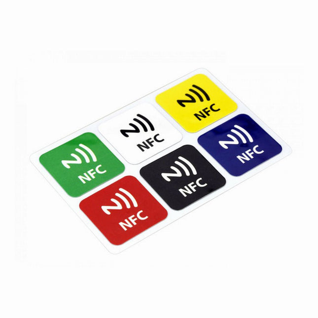
Features NFC chip material: PET + Etching antenna Chip: NTAG216 (compatible with all NFC phones) Frequency: 13.56 MHz (High Frequency) Reading time: 1 - 2 ms Storage capacity: 888 bytes Read and write times: > 100,000 times Reading distance: 0 - 5 mm Data retention: > 10 years NFC chip size: Diameter 30 mm Non-contact, no friction, the failure rate is small, low maintenance costs Read rate, verification speed, which can effectively save time and improve efficiency Waterproof, dustproof, anti-vibration No power comes with an antenna, embedded encryption control logic, and communication logic circuit Included 1x NFC Stickers (6-color kit)
The perfect tool for quick repairs
The FNIRSI HS-01 is a powerful, adjustable smart soldering iron with a built-in 0.87-inch OLED display that quickly reaches temperatures between 80-420°C (180-780°F). The display shows all important information, including the status of the temperature level, the set temperature, the supply voltage and the power percentage. You can set the input voltage from 9-20 V directly in the menu according to your needs. The integrated sleep mode automatically turns off the iron after 30 minutes.
Features
96 W input (DC)
65 W PD power
OLED display
Constant temperature & fast heating
CNC metal integral molding
Smart safety anti-scald
Mini pocket size
Ergonomic design
Aluminum material
Left/right hand switch
Efficient heat radiation
Inductive sleep
Color: Black
Specifications
Power
65 W
Screen
0.87" OLED
Operating voltage
9-20 VDC
Power supply
USB-C
Temperature range
80-420°C (180-780°F)
Fast charging protocol
PD trigger
Dimensions
184 x 20 x 20 mm (7.24 x 0.79 x 0.79')
Weight
56 g
Power Selection
Operating voltage
20 V
15 V
12 V
9 V
Operating current
≥3.25 A
≥2.5 A
≥2 A
≥1.5 A
Power
65 W
37.5 W
24 W
13.5 W
Tin melting time
8s
12s
17s
30s
Included
1x FNRISI HS-01 smart soldering iron
6x Soldering iron tips (HS01-BC2, HS01-KR, HS01-K65, HS01-B2, HS01-ILS, HS01-BC3)
1x DC to USB-C power cable
1x Mini soldering iron stand
1x Manual
Required
Power adapter
USB-C cable
Downloads
Manual
Firmware V0.3.s19