Search results for "greatfet OR one"
-

Great Scott Gadgets Acrylic Case for HackRF One/Pro SDR
This clear acrylic case is the official case for the HackRF One/Pro board. It can replace the standard black plastic case of the HackRF One/Pro. Assembly Instructions Use a guitar pick or spudger to extract the HackRF One/Pro circuit board from the black plastic case. Insert one long screw into each corner of the bottom acrylic panel. Secure each long screw with a short (5 mm) spacer on the opposite side of the panel. Place the HackRF One/Pro circuit board (facing up) on top of the bottom panel, fitting the ends of the long screws through the corner mounting holes of the circuit board. Secure the circuit board with one long (6 mm) spacer in each corner. Place the top acrylic panel on top of the circuit board, aligning the cutouts with the circuit board’s expansion headers. Secure each corner with a short screw. Note: Do not overtighten! Hand-tighten only at every step.
€ 19,95
Members: € 17,96
-
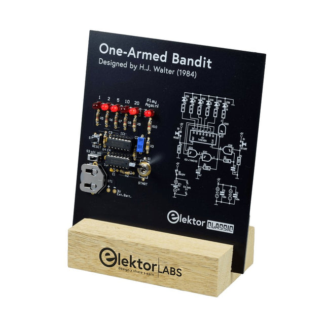
Elektor Labs Elektor One-armed Bandit
Pull Down Lever For Highest Score! This Elektor Circuit Classic from 1984 shows a playful application of CMOS 400x series logic ICs in combination with LEDs, a highly popular combination at the time. The project imitates a spinning-digit type slot machine. The Game To play the game, first agree on the number of rounds. Player 1 actuates the switch lever as long as desired and releases it. The LEDs then show the score which is the sum of the 50-20-10-5 digits lit up. If the Play Again! LED lights, Player 1 has another, “free” round. If not, it’s Player 2’s turn. The players keep tab of their scores, and the highest score wins. Features LEDs Indicate Score Multi-Player and Play Again! Elektor Heritage Circuit Symbols Tried & Tested by Elektor Labs Educational & Geeky Project Through-Hole Parts Only Included Printed Circuit Board All Components Wooden Stand Bill of Materials Resistors (5%, 250 mW) R1,R2,R3,R4 = 100kΩ R5,R6,R7,R8,R9,R10 = 1kΩ Capacitors C1 = 4.7nF, 10%, 50V, 5mm C2 = 4.7μF, 10%, 63V, axial C3,C4 = 100nF, 10 %, 50V, ceramic X7R, 5mm Semiconductors LED1-LED6 = red, 5mm (T1 3/4) IC1 = 74HC4024 IC2 = 74HC132 Miscellaneous S1 = switch, toggle, 21mm lever, SPDT, momentary S2 = switch, tactile, 24V, 50mA, 6x6mm S3 = switch, slide, SPDT IC1,IC2 = IC socket, DIP14 BT1 = PCB-mount CR2032 battery retainer clip Desktop Stand PCB 230098-1 Not included: BT1 = CR2032 coin cell battery
€ 39,95€ 15,98
Best Price
-

Elektor Digital Oscilloscopes (E-book)
Understanding and Using Them Effectively What happens in electronics is invisible to the naked eye. The instrument that allows to accurately visualize electrical signals, the one through which the effects of electronics become apparent to us, is the oscilloscope. Alas, when one first ventures into electronics, it is often without an oscilloscope. And one is left fumbling, both physically and mentally. Observing an electrical signal on a screen for the first time is a revelation. Nobody wishes to forgo that marvel again. There is no turning back. In electronics, if one wishes to progress with both enjoyment and understanding, an oscilloscope is essential. This marks the beginning of a period of questioning: how to choose one? And no sooner is that question answered than a whole string of others arises, which can be summed up in just one: how does one use the oscilloscope in such a way that what it displays truly reflects the reality of the signals? Rémy Mallard is a passionate communicator with a gift for making complex technical subjects understandable and engaging. In this book, he provides clear answers to essential questions about using an oscilloscope and offers a wealth of guidance to help readers explore and understand the electrical signals behind electronic systems. With his accessible style and practical insights, this book is a valuable tool for anyone eager to deepen their understanding of electronics.
€ 34,95
Members: € 27,96
-
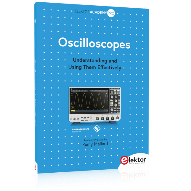
Elektor Publishing Oscilloscopes (Book)
Understanding and Using Them Effectively What happens in electronics is invisible to the naked eye. The instrument that allows to accurately visualize electrical signals, the one through which the effects of electronics become apparent to us, is the oscilloscope. Alas, when one first ventures into electronics, it is often without an oscilloscope. And one is left fumbling, both physically and mentally. Observing an electrical signal on a screen for the first time is a revelation. Nobody wishes to forgo that marvel again. There is no turning back. In electronics, if one wishes to progress with both enjoyment and understanding, an oscilloscope is essential. This marks the beginning of a period of questioning: how to choose one? And no sooner is that question answered than a whole string of others arises, which can be summed up in just one: how does one use the oscilloscope in such a way that what it displays truly reflects the reality of the signals? Rémy Mallard is a passionate communicator with a gift for making complex technical subjects understandable and engaging. In this book, he provides clear answers to essential questions about using an oscilloscope and offers a wealth of guidance to help readers explore and understand the electrical signals behind electronic systems. With his accessible style and practical insights, this book is a valuable tool for anyone eager to deepen their understanding of electronics.
€ 44,95
Members: € 40,46
-
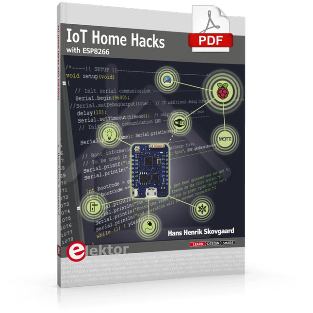
Elektor Digital IoT Home Hacks with ESP8266 (E-book)
There are many so-called 'Arduino compatible' platforms on the market. The ESP8266 – in the form of the WeMos D1 Mini Pro – is one that really stands out. This device includes WiFi Internet access and the option of a flash file system using up to 16 MB of external flash memory. Furthermore, there are ample in/output pins (though only one analogue input), PWM, I²C, and one-wire. Needless to say, you are easily able to construct many small IoT devices! This book contains the following builds: A colourful smart home accessory refrigerator controller 230 V power monitor door lock monitor and some further spin-off devices. All builds are documented together with relevant background information for further study. For your convenience, there is a small PCB for most of the designs; you can also use a perf board. You don’t need to be an expert but the minimum recommended essentials include basic experience with a PC, software, and hardware, including the ability to surf the Internet and assemble PCBs. And of course: A handle was kept on development costs. All custom software for the IoT devices and PCB layouts are available for free download from at Elektor.com.
€ 34,95
Members: € 27,96
-

Elektor Digital Vanderveen Trans Tube Amplifiers (E-book)
Menno van der Veen is well known for his research publications on tube amplifiers used in audio systems. In this book he describes one of his research projects which focuses on the question of whether full compensation for distortion in tubes and output transformers is possible. In the past, a variety of techniques have been developed. One of them has largely been forgotten: trans-conductance, which means converting current into voltage or voltage into current. Menno van der Veen has breathed new life into this technique with his research project titled “Trans”. This book discusses all aspects of this method and discusses its pitfalls. These pitfalls are addressed one by one. The end result is a set of stringent requirements for Trans amplifiers. Armed with these requirements, Menno then develops new Trans amplifiers, starting with Transie 1 and Transie 2. These DC-coupled, single-ended tube amplifiers have unusually good characteristics and are suitable for hobbyist construction. Next the Trans principle is applied to amplifiers with higher output power. A trial-and-error process ultimately leads to the Vanderveen Trans 30 amplifier, which optimizes the features of Trans. The characteristics of this amplifier are so special and unique that Menno believes he has struck gold. To ensure that variations in tube characteristics cannot interfere with optimal Trans behavior, Menno makes use of simulations and comparison with other amplifier types. This book reads like an adventure story, but it is much more – it is an account of solid research into new ways to achieve optimal audio reproduction.
€ 29,95
Members: € 23,96
-
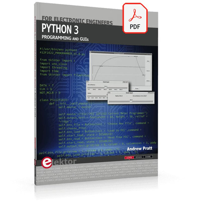
Elektor Digital Python 3 Programming and GUIs (E-book)
This is the second edition of a book aimed at engineers, scientists, and hobbyists who want to interface PCs with hardware projects using graphical user interfaces. Desktop and web-based applications are covered. The programming language used is Python 3, which is one of the most popular languages around: speed of programming being a key feature. The book has been revised and updated with an emphasis on getting the user to produce practical designs with ease – a text editor is all that is required to produce Python programs. Hardware interfacing is achieved using an Arduino Uno as a remote slave. A full description and source code of the communication interface is given in the book. The slave provides digital and analog input and outputs. Multiple Unos can be included in one project with all control code written in Python and running on a PC One project involves a PIC microcontroller with the code provided that can be loaded into the PIC using the Uno. The web applications and server are all implemented in Python, allowing you to access your electronic hardware over the Internet. The Raspberry Pi computer can be used as your web server. An introductory chapter is provided to get you started with using Linux. The book is written for use with Debian or variations including Mint or Ubuntu. All of the programs in the book are freely available, ready to use and experiment with by way of a download from Elektor.
€ 29,95
Members: € 23,96
-
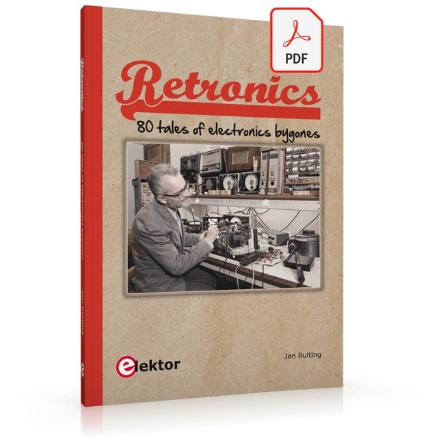
Elektor Digital Retronics (E-book)
Quite unintentionally a one-page story on an old Heathkit tube tester in the December 2004 edition of Elektor magazine spawned dozens of ‘Retronics’ tales appearing with a monthly cadence, and attracting a steady flow of reader feedback and contributions to the series. Since launching his Retronics columns, Elektor Editor Jan Buiting has never been short of copy to print, or vintage equipment to marvel at. This book is a compilation of about 80 Retronics installments published between 2004 and 2012. The stories cover vintage test equipment, prehistoric computers, long forgotten components, and Elektor blockbuster projects, all aiming to make engineers smile, sit up, object, drool, or experience a whiff of nostalgia. To reflect that our memories are constantly playing tricks on us, and honoring that “one man’s rubbish is another man’s gem”, the tales in the book purposely have no chronological order, and no bias in favor of transistor or tube, microprocessor or discrete part, audio or RF, DIY or professional, dry or narrative style. Although vastly diff erent in subject matter, all tales in the book are told with personal gusto because Retronics is about sentiment in electronics engineering, construction and repair, be it to reminisce about a 1960s Tektronix scope with a cleaning lady as a feature, or a 1928 PanSanitor box for dubious medical use. Owners of this book are advised to not exceed one Retronics tale per working day, preferably consumed in the evening hours under lamp light, in a comfortable chair, with a piece of vintage electronic equipment close and powered up.
€ 24,95
Members: € 19,96
-
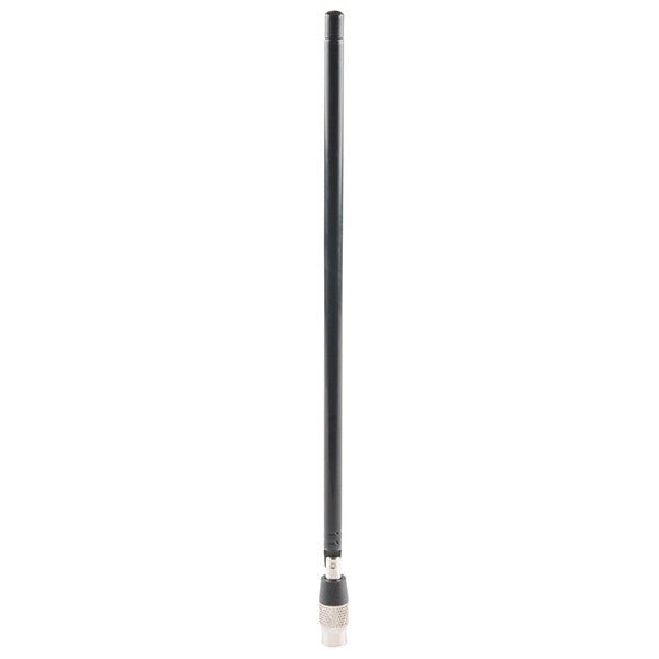
Great Scott Gadgets Great Scott Gadgets ANT500 Telescopic Antenna (75 MHz – 1 GHz)
ANT500 from Great Scott Gadgets is a telescopic antenna designed for operation from 75 MHz to 1 GHz. Its total length is configurable from 20 cm to 88 cm. ANT500 is constructed of stainless steel and features an SMA male connector, rotating shaft, and adjustable elbow. ANT500 is a 50 ohm general purpose antenna. It is the perfect first antenna for use with HackRF One/Pro.
€ 34,95
Members: € 31,46
-

Elektor Digital Controller Area Network Projects with ARM and Arduino (E-book)
This book details the use of the ARM Cortex-M family of processors and the Arduino Uno in practical CAN bus based projects. Inside, it gives a detailed introduction to the architecture of the Cortex-M family whilst providing examples of popular hardware and software development kits. Using these kits helps to simplify the embedded design cycle considerably and makes it easier to develop, debug, and test a CAN bus based project. The architecture of the highly popular ARM Cortex-M processor STM32F407VGT6 is described at a high level by considering its various modules. In addition, the use of the mikroC Pro for ARM and Arduino Uno CAN bus library of functions are described in detail. This book is written for students, for practising engineers, for hobbyists, and for everyone else who may need to learn more about the CAN bus and its applications. The book assumes that the reader has some knowledge of basic electronics. Knowledge of the C programming language will be useful in later chapters of the book, and familiarity with at least one microcontroller will be an advantage, especially if the reader intends to develop microcontroller based projects using CAN bus. The book should be useful source of reference to anyone interested in finding an answer to one or more of the following questions: What bus systems are available for the automotive industry? What are the principles of the CAN bus? What types of frames (or data packets) are available in a CAN bus system? How can errors be detected in a CAN bus system and how reliable is a CAN bus system? What types of CAN bus controllers are there? What are the advantages of the ARM Cortex-M microcontrollers? How can one create a CAN bus project using an ARM microcontroller? How can one create a CAN bus project using an Arduino microcontroller? How can one monitor data on the CAN bus?
€ 32,95
Members: € 26,36
-
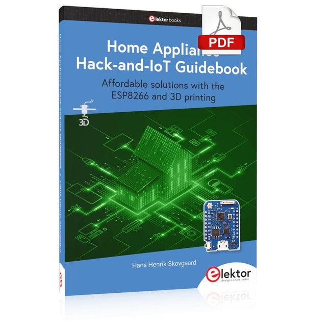
Elektor Digital Home Appliance Hack-and-IoT Guidebook (E-book)
Affordable solutions with the ESP8266 and 3D printing If you are looking for a small yet powerful IoT device, you are likely to come across the ESP8266 and compatible products on the market today. One of these, the Wemos/Lolin D1 Mini Pro board strikes a remarkable balance between cost and performance. A small and very affordable prototype board, the D1 Mini Pro stands out with its WiFi functionality and a 16-Mbytes flash memory for easy creation of a flash file system. In addition, there are sufficient input and output pins (only one analog input though) to support PWM, I²C, and One-Wire systems to mention but a few. The book describes the operation, modding, construction, and programming of home appliances including a colorful smart home accessory, a refrigerator/greenhouse controller, an AC powerline monitor, a door lock monitor, and an IKEA Trådfri controller. As a benefit, all firmware developed for these DIY, "IoT-ized" devices can be updated over-the-air (OTA). For most of the designs in the book, a small printed circuit board (PCB) and an enclosure are presented so readers can have a finished and attractive-looking product. Readers having – or with access to! – a 3D printer can "print" the suggested enclosures at home or in a shop. Some of the constructions benefit from a Raspberry Pi configured as a gateway or cms server. This is also described in detail with all the necessary configuring. You don’t need to be an expert but the prerequisites to successful replication of the projects include basic skills with PC software including the ability to surf the Internet. In terms of hardware, you should be comfortable with soldering and generally assembling the PCBs presented in the book. All custom software written for the IoT devices, the PCB layouts, and 3D print files described in the book are available for free downloading.
€ 34,95
Members: € 27,96


-

, by Burkhard Kainka First Experiences with HackRF One – a Review
When I first held the HackRF One in my hand, I knew almost nothing about it, except that it is an SDR receiver and transmitter up...
