This bundle contains the popular Elektor Sand Clock for Raspberry Pi Pico and the new Elektor Laser Head Upgrade, offering even more options for displaying the time. Not only can you "engrave" the current time in sand, you can now alternatively write it on a glow-in-the-dark foil or create green drawings.
Contents of the bundle
Elektor Sand Clock for Raspberry Pi Pico (normal price: €50)
Elektor Laser Head Upgrade for Sand Clock (normal price: €35)
Elektor Sand Clock for Raspberry Pi (Raspberry Pi-based Eye Catcher)
A standard sand clock just shows how time passes. In contrast, this Raspberry Pi Pico-controlled sand clock shows the exact time by "engraving" the four digits for hour and minute into the layer of sand. After an adjustable time the sand is flattened out by two vibration motors and everything begins all over again.
At the heart of the sand clock are two servo motors driving a writing pen through a pantograph mechanism. A third servo motor lifts the pen up and down. The sand container is equipped with two vibration motors to flatten the sand. The electronic part of the sand clock consists of a Raspberry Pi Pico and an RTC/driver board with a real-time clock, plus driver circuits for the servo motors.
A detailed construction manual is available for downloading.
Features
Dimensions: 135 x 110 x 80 mm
Build time: approx. 1.5 to 2 hours
Included
3x Precut acrylic sheets with all mechanical parts
3x Mini servo motors
2x Vibration motors
1x Raspberry Pi Pico
1x RTC/driver board with assembled parts
Nuts, bolts, spacers, and wires for the assembly
Fine-grained white sand
Elektor Laser Head Upgrade for Sand Clock
The new Elektor Laser Head transforms the Sand Clock into a clock that writes the time on glow-in-the-dark film instead of sand. In addition to displaying the time, it can also be used to create ephemeral drawings. The 5 mW laser pointer, with a wavelength of 405 nm, produces bright green drawings on the glow-in-the-dark film. For best results, use the kit in a dimly lit room. Warning: Never look directly into the laser beam!
The kit includes all the necessary components, but soldering three wires is required.
Note: This kit is also compatible with the original Arduino-based Sand Clock from 2017. For more details, see Elektor Magazine 1-2/2017 and Elektor Magazine 1-2/2018.
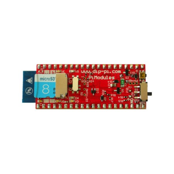
The DiP-Pi PIoT is an Advanced Powered, WiFi connectivity System with sensors embedded interfaces that cover most of possible needs for IoT application based on Raspberry Pi Pico. It can supply the system with up to 1.5 A @ 4.8 V delivered from 6-18 VDC on various powering schemes like Cars, Industrial plant etc., additionally to original micro-USB of the Raspberry Pi Pico. It supports LiPo or Li-Ion Battery with Automatic Charger as also automatic switching from cable powering to battery powering or reverse (UPS functionality) when cable powering lost. Extended Powering Source (EPR) is protected with PPTC Resettable fuse, Reverse Polarity, as also ESD.
The DiP-Pi PIoT contains Raspberry Pi Pico embedded RESET button as also ON/OFF Slide Switch that is acting on all powering sources (USB, EPR or Battery). User can monitor (via Raspberry Pi Pico A/D pins) battery level and EPR Level with PICO’s A/D converters. Both A/D inputs are bridged with 0402 resistors (0 OHM) therefore if for any reason user needs to use those Pico pins for their own application can be easy removed. The charger is automatically charging connected battery (if used) but in addition user can switch charger ON/OFF if their application needs it.
DiP-Pi PIoT can be used for cable powered IoT systems, but also for pure Battery Powered System with ON/OFF. Each powering source status is indicated by separate informative LEDs (VBUS, VSYS, VEPR, CHGR, V3V3).
User can use any capacity of LiPo or Li-Ion type; however, must take care to use PCB protected batteries with max discharge current allowed of 2 A. The embedded battery charger is set to charge battery with 240 mA current. This current is set by resistor so if user need more/less can himself to change it. The DiP-Pi PIoT is also equipped with WiFi ESP8266 Clone module with embedded antenna. This feature open a wide range of IoT applications based on it.
In Addition to all above features DiP-Pi PIoT is equipped with embedded 1-wire, DHT11/22 sensors, and micro–SD Card interfaces. Combination of the extended powering, battery, and sensors interfaces make the DiP-Pi PIoT ideal for IoT applications like data logger, plants monitoring, refrigerators monitoring etc.
DiP-Pi PIoT is supported with plenty of ready to use examples written in Micro Python or C/C++.
Specifications
General
Dimensions 21 x 51 mm
Raspberry Pi Pico pinout compatible
Independent Informative LEDs (VBUS, VSYS, VEPR, CHGR, V3V3)
Raspberry Pi Pico RESET Button
ON/OFF Slide Switch acting on all powering sources (USB, EPR, Battery)
External Powering 6-18 VDC (Cars, Industrial Applications etc.)
External Power (6-18 VDC) Level Monitoring
Battery Level Monitoring
Inverse Polarity Protection
PPTC Fuse Protection
ESD Protection
Automatic Battery Charger (for PCB protected LiPo, Li-Ion – 2 A Max) Automatic/User Control
Automatic Switch from Cable Powering to Battery Powering and reverse (UPS Functionality)
Various powering schemes can be used at the same time with USB Powering, External Powering and Battery Powering
1.5 A @ 4.8 V Buck Converter on EPR
Embedded 3.3 V @ 600 mA LDO
ESP8266 Clone WiFi Connectivity
ESP8266 Firmware Upload Switch
Embedded 1-wire Interface
Embedded DHT-11/22 Interface
Powering Options
Raspberry Pi Pico micro-USB (via VBUS)
External Powering 6-18 V (via dedicated Socket – 3.4/1.3 mm)
External Battery
Supported Battery Types
LiPo with protection PCB max current 2A
Li-Ion with protection PCB max current 2A
Embedded Peripherals and Interfaces
Embedded 1-wire interface
Embedded DHT-11/22 Interface
Micro SD Card Socket
Programmer Interface
Standard Raspberry Pi Pico C/C++
Standard Raspberry Pi Pico Micro Python
Case Compatibility
DiP-Pi Plexi-Cut Case
System Monitoring
Battery Level via Raspberry Pi Pico ADC0 (GP26)
EPR Level via Raspberry Pi Pico ADC1 (GP27)
Informative LEDs
VB (VUSB)
VS (VSYS)
VE (VEPR)
CH (VCHR)
V3 (V3V3)
System Protection
Direct Raspberry Pi Pico Hardware Reset Button
ESD Protection on EPR
Reverse Polarity Protection on EPR
PPTC 500 mA @ 18 V fuse on EPR
EPR/LDO Over Temperature protection
EPR/LDO Over Current protection
System Design
Designed and Simulated with PDA Analyzer with one of the most advanced CAD/CAM Tools – Altium Designer
Industrial Originated
PCB Construction
2 ozcopper PCB manufactured for proper high current supply and cooling
6 mils track/6 mils gap technology 2 layers PCB
PCB Surface Finishing – Immersion Gold
Multi-layer Copper Thermal Pipes for increased System Thermal Response and better passive cooling
Downloads
Datasheet
Manual
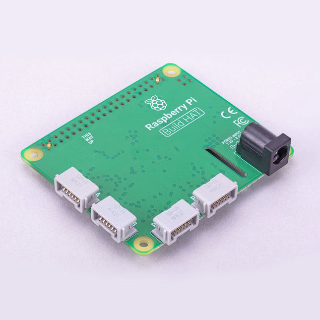
Build robust, intelligent machines that combine Raspberry Pi computing power with LEGO components.
The Raspberry Pi Build HAT provides four connectors for LEGO Technic motors and sensors from the SPIKE Portfolio. The available sensors include a distance sensor, a color sensor, and a versatile force sensor. The angular motors come in a range of sizes and include integrated encoders that can be queried to find their position.
The Build HAT fits all Raspberry Pi computers with a 40-pin GPIO header, including – with the addition of a ribbon cable or other extension device — Raspberry Pi 400. Connected LEGO Technic devices can easily be controlled in Python, alongside standard Raspberry Pi accessories such as a camera module.
Features
Controls up to 4 motors and sensors
Powers the Raspberry Pi (when used with a suitable external PSU)
Easy to use from Python on the Raspberry Pi
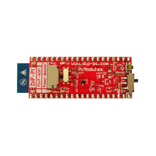
The DiP-Pi WiFi Master is an Advanced WiFi connectivity System with sensors embedded interfaces that cover most of possible needs for IoT application based on Raspberry Pi Pico. It is powered directly from the Raspberry Pi Pico VBUS. The DiP-Pi WiFi Master contains Raspberry Pi Pico embedded RESET button as also ON/OFF Slide Switch that is acting on Raspberry Pi Pico Power Sources.
The DiP-Pi WiFi Master is equipped with WiFi ESP8266 Clone module with embedded antenna. This feature open a wide range of IoT applications based on it.
In Addition to all above features DiP-Pi WiFi Master is equipped with embedded 1-wire, DHT11/22 sensors, and micro–SD Card interfaces. Combination of the extended powering, battery, and sensors interfaces make the DiP-Pi WiFi Master ideal for IoT applications like data logger, plants monitoring, refrigerators monitoring etc.
DiP-Pi WiFi Master is supported with plenty of ready to use examples written in Micro Python or C/C++.
Specifications
General
Dimensions 21 x 51 mm
Raspberry Pi Pico pinout compatible
Independent Informative LEDs (VBUS, VSYS, V3V3)
Raspberry Pi Pico RESET Button
ON/OFF Slide Switch acting on Raspberry Pi Pico Powering Source
Embedded 3.3 V @ 600 mA LDO
ESP8266 Clone WiFi Connectivity
ESP8266 Firmware Upload Switch
Embedded 1-wire Interface
Embedded DHT-11/22 Interface
Powering Options
Raspberry Pi Pico micro-USB (via VBUS)
Embedded Peripherals and Interfaces
Embedded 1-wire interface
Embedded DHT-11/22 Interface
Micro SD Card Socket
Programmer Interface
Standard Raspberry Pi Pico C/C++
Standard Raspberry Pi Pico Micro Python
Case Compatibility
DiP-Pi Plexi-Cut Case
Informative LEDs
VB (VUSB)
VS (VSYS)
V3 (V3V3)
System Protection
Direct Raspberry Pi Pico Hardware Reset Button
PPTC 500 mA @ 18 V fuse on EPR
EPR/LDO Over Temperature protection
EPR/LDO Over Current protection
System Design
Designed and Simulated with PDA Analyzer with one of the most advanced CAD/CAM Tools – Altium Designer
Industrial Originated
PCB Construction
2 ozcopper PCB manufactured for proper high current supply and cooling
6 mils track/6 mils gap technology 2 layers PCB
PCB Surface Finishing – Immersion Gold
Multi-layer Copper Thermal Pipes for increased System Thermal Response and better passive cooling
Downloads
Datasheet
Manual
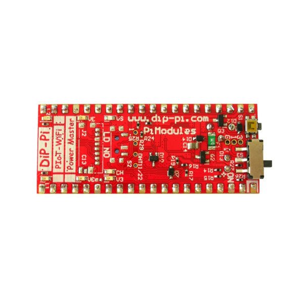
The DiP-Pi Power Master is an Advanced Powering System with embedded sensors interfaces that cover most of possible needs for application based on Raspberry Pi Pico. It can supply the system with up to 1.5 A @ 4.8 V delivered from 6-18 VDC on various powering schemes like Cars, Industrial plant etc., additionally to original micro-USB of the Raspberry Pi Pico. It supports LiPo or Li-Ion Battery with Automatic Charger as also automatic switching from cable powering to battery powering or reverse (UPS functionality) when cable powering lost. Extended Powering Source (EPR) is protected with PPTC Resettable fuse, Reverse Polarity, as also ESD.
The DiP-Pi Power Master contains Raspberry Pi Pico embedded RESET button as also ON/OFF Slide Switch that is acting on all powering sources (USB, EPR or Battery). User can monitor (via Raspberry Pi Pico A/D pins) battery level and EPR Level with PICO’s A/D converters. Both A/D inputs are bridged with 0402 resistors (0 OHM) therefore if for any reason user needs to use those Pico pins for their own application can be easy removed. The charger is automatically charging connected battery (if used) but in addition user can switch charger ON/OFF if their application needs it. DiP-Pi Power Master can be used for cable powered systems, but also for pure Battery Powered System with ON/OFF. Each powering source status is indicated by separate informative LEDs (VBUS, VSYS, VEPR, CHGR, V3V3).
User can use any capacity of LiPo or Li-Ion type; however, must take care to use PCB protected batteries with max discharge current allowed of 2 A. The embedded battery charger is set to charge battery with 240 mA current. This current is set by resistor so if user need more/less can himself to change it.
In Addition to all above features DiP-Pi Power Master is equipped with embedded 1-wire and DHT11/22 sensors interfaces. Combination of the extended powering, battery, and sensors interfaces make the DiP-Pi Power Master ideal for applications like data logger, plants monitoring, refrigerators monitoring etc.
DiP-Pi Power Master is supported with plenty of ready to use examples written in Micro Python or C/C++.
Specifications
General
Dimensions 21 x 51 mm
Raspberry Pi Pico pinout compatible
Independent Informative LEDs (VBUS, VSYS, VEPR, CHGR, V3V3)
Raspberry Pi Pico RESET Button
ON/OFF Slide Switch acting on all powering sources (USB, EPR, Battery)
External Powering 6-18 V DC (Cars, Industrial Applications etc.)
External Power (6-18 VDC) Level Monitoring
Battery Level Monitoring
Inverse Polarity Protection
PPTC Fuse Protection
ESD Protection
Automatic Battery Charger (for PCB protected LiPo, Li-Ion – 2 A Max) Automatic/User Control
Automatic Switch from Cable Powering to Battery Powering and reverse (UPS Functionality)
Various powering schemes can be used at the same time with USB Powering, External Powering and Battery Powering
1.5 A @ 4.8 V Buck Converter on EPR
Embedded 3.3 V @ 600mA LDO
Embedded 1-wire Interface
Embedded DHT-11/22 Interface
Powering Options
Raspberry Pi Pico micro-USB (via VBUS)
External Powering 6-18 V (via dedicated Socket – 3.4/1.3 mm)
External Battery
Supported Battery Types
LiPo with protection PCB max current 2A
Li-Ion with protection PCB max current 2A
Embedded Peripherals and Interfaces
Embedded 1-wire interface
Embedded DHT-11/22 Interface
Programmer Interface
Standard Raspberry Pi Pico C/C++
Standard Raspberry Pi Pico Micro Python
Case Compatibility
DiP-Pi Plexi-Cut Case
System Monitoring
Battery Level via Raspberry Pi Pico ADC0 (GP26)
EPR Level via Raspberry Pi Pico ADC1 (GP27)
Informative LEDs
VB (VUSB)
VS (VSYS)
VE (VEPR)
CH (VCHR)
V3 (V3V3)
System Protection
Direct Raspberry Pi Pico Hardware Reset Button
ESD Protection on EPR
Reverse Polarity Protection on EPR
PPTC 500 mA @ 18 V fuse on EPR
EPR/LDO Over Temperature protection
EPR/LDO Over Current protection
System Design
Designed and Simulated with PDA Analyzer with one of the most advanced CAD/CAM Tools – Altium Designer
Industrial Originated
PCB Construction
2 ozcopper PCB manufactured for proper high current supply and cooling
6 mils track/6 mils gap technology 2 layers PCB
PCB Surface Finishing – Immersion Gold
Multi-layer Copper Thermal Pipes for increased System Thermal Response and better passive cooling
Downloads
Datasheet
Datasheet
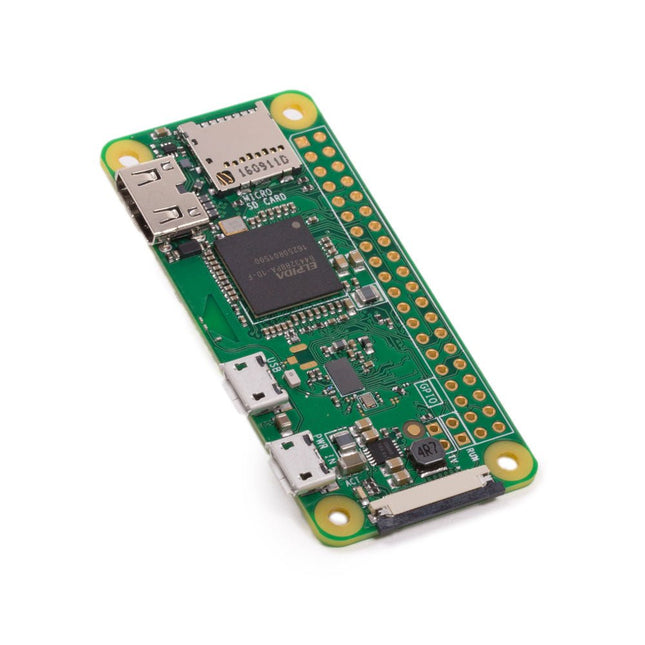
The Raspberry Pi Zero W extends the Raspberry Pi Zero family. The Raspberry Pi Zero W has all the functionality of the original Raspberry Pi Zero, but comes with added connectivity consisting of:
802.11 b/g/n wireless LAN
Bluetooth 4.1
Bluetooth Low Energy (BLE)
Other Features
1 GHz, single-core CPU
512 MB RAM
Mini HDMI and USB On-The-Go ports
Micro-USB power
HAT-compatible 40-pin header
Composite video and reset headers
CSI camera connector
Downloads
Mechanical Drawing
Schematics
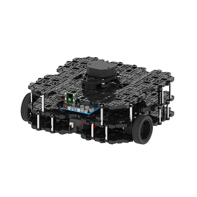
World’s Most Popular ROS Platform TurtleBot is the most popular open source robot for education and research. The new generation TurtleBot3 is a small, low cost, fully programmable, ROS based mobile robot. It is intended to be used for education, research, hobby and product prototyping. Affordable Cost TurtleBot was developed to meet the cost-conscious needs of schools, laboratories and companies. TurtleBot3 is the most affordable robot among the SLAM-able mobile robots equipped with a 360° Laser Distance Sensor LDS-01. ROS Standard The TurtleBot brand is managed by Open Robotics, which develops and maintains ROS. Nowadays, ROS has become the go-to platform for all the roboticists around the world. TurtleBot can be integrated with existing ROS-based robot components, but TurtleBot3 can be an affordable platform for whom want to get started learning ROS. Extensibility TurtleBot3 encourages users to customize its mechanical structure with some alternative options: open source embedded board (as a control board), computer and sensors. TurtleBot3 Waffle Pi is a two-wheeled differential drive type platform but it is able to be structurally and mechanically customized in many ways: Cars, Bikes, Trailers and so on. Extend your ideas beyond imagination with various SBC, sensors and motors on a scalable structure. Modular Actuator for Mobile Robot TurtleBot3 is able to get a precise spatial data by using 2 DYNAMIXEL’s in the wheel joints. DYNAMIXEL XM series can be operated by one of 6 operating modes (XL series: 4 operating modes): Velocity control mode for wheels, Torque control mode or Position control mode for joint, etc. DYNAMIXEL can be used even to make a mobile manipulator which is light but can be precisely controlled with velocity, torque and position control. DYNAMIXEL is a core component that makes TurtleBot3 perfect. It is easy to assemble, maintain, replace and reconfigure. Open Control Board for ROS The control board is open-sourced in hardware wise and in software wise for ROS communication. The open source control board OpenCR1.0 is powerful enough to control not only DYNAMIXEL’s but also ROBOTIS sensors that are frequently being used for basic recognition tasks in cost effective way. Various sensors such as Touch sensor, Infrared sensor, Color sensor and a handful more are available. The OpenCR1.0 has an IMU sensor inside the board so that it can enhance precise control for countless applications. The board has 3.3 V, 5 V, 12 V power supplies to reinforce the available computer device lineups. Open Source The hardware, firmware and software of TurtleBot3 are open source which means that users are welcomed to download, modify and share source codes. All components of TurtleBot3 are manufactured with injection molded plastic to achieve low cost, however, the 3D CAD data is also available for 3D printing. Specifications Maximum translational velocity 0.26 m/s Maximum rotational velocity 1.82 rad/s (104.27 deg/s) Maximum payload 30 kg Size (L x W x H) 281 x 306 x 141 mm Weight (+ SBC + Battery + Sensors) 1.8 kg Threshold of climbing 10 mm or lower Expected operating time 2h Expected charging time 2h 30m SBC (Single Board Computers) Raspberry Pi 4 (2 GB RAM) MCU 32-bit ARM Cortex-M7 with FPU (216 MHz, 462 DMIPS) Remote Controller RC-100B + BT-410 Set (Bluetooth 4, BLE) Actuator XL430-W210 LDS (Laser Distance Sensor) 360 Laser Distance Sensor LDS-01 or LDS-02
Camera Raspberry Pi Camera Module v2.1 IMU Gyroscope 3 AxisAccelerometer 3 Axis Power connectors 3.3 V/800 mA5 V/4 A12 V/1 A Expansion pins GPIO 18 pinsArduino 32 pin Peripheral 3x UART, 1x CAN, 1x SPI, 1x I²C, 5x ADC, 4x 5-pin OLLO DYNAMIXEL ports 3x RS485, 3x TTL Audio Several programmable beep sequences Programmable LEDs 4x User LED Status LEDs 1x Board status LED1x Arduino LED1x Power LED Buttons and Switches 2x Push buttons, 1x Reset button, 2x Dip switch Battery Lithium polymer 11.1 V 1800 mAh / 19.98 Wh 5C PC connection USB Firmware upgrade via USB / via JTAG Power adapter (SMPS) Input: 100-240 VAC 50/60 Hz, 1.5 A @maxOutput: 12 VDC, 5 A Downloads ROS Robot Programming GitHub E-Manual Community
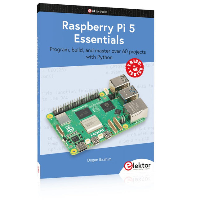
Program, build, and master over 60 projects with Python
The Raspberry Pi 5 is the latest single-board computer from the Raspberry Pi Foundation. It can be used in many applications, such as in audio and video media centers, as a desktop computer, in industrial controllers, robotics, and in many domestic and commercial applications. In addition to the well-established features found in other Raspberry Pi computers, the Raspberry Pi 5 offers Wi-Fi and Bluetooth (classic and BLE), which makes it a perfect match for IoT as well as in remote and Internet-based control and monitoring applications. It is now possible to develop many real-time projects such as audio digital signal processing, real-time digital filtering, real-time digital control and monitoring, and many other real-time operations using this tiny powerhouse.
The book starts with an introduction to the Raspberry Pi 5 computer and covers the important topics of accessing the computer locally and remotely. Use of the console language commands as well as accessing and using the desktop GUI are described with working examples. The remaining parts of the book cover many Raspberry Pi 5-based hardware projects using components and devices such as
LEDs and buzzers
LCDs
Ultrasonic sensors
Temperature and atmospheric pressure sensors
The Sense HAT
Camera modules
Example projects are given using Wi-Fi and Bluetooth modules to send and receive data from smartphones and PCs, and sending real-time temperature and atmospheric pressure data to the cloud.
All projects given in the book have been fully tested for correct operation. Only basic programming and electronics experience are required to follow the projects. Brief descriptions, block diagrams, detailed circuit diagrams, and full Python program listings are given for all projects described.
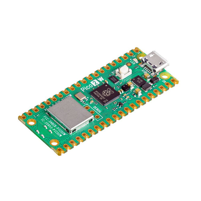
The Raspberry Pi Pico 2 W is a microcontroller board based on the RP2350 featuring 2.4 GHz 802.11n wireless LAN and Bluetooth 5.2. It gives you even more flexibility in your IoT or smart product designs and expanding the possibilities for your projects.
The RP2350 provides a comprehensive security architecture built around Arm TrustZone for Cortex-M. It incorporates signed boot, 8 KB of antifuse OTP for key storage, SHA-256 acceleration, a hardware TRNG, and fast glitch detectors.
The unique dual-core, dual-architecture capability of the RP2350 allows users to choose between a pair of industry-standard Arm Cortex-M33 cores and a pair of open-hardware Hazard3 RISC-V cores. Programmable in C/C++ and Python, and supported by detailed documentation, the Raspberry Pi Pico 2 W is the ideal microcontroller board for both enthusiasts and professional developers.
Specifications
CPU
Dual Arm Cortex-M33 or dual RISC-V Hazard3 processors @ 150 MHz
Wireless
On-board Infineon CYW43439 single-band 2.4 GHz 802.11n wireless Lan and Bluetooth 5.2
Memory
520 KB on-chip SRAM; 4 MB on-board QSPI flash
Interfaces
26 multi-purpose GPIO pins, including 4 that can be used for AD
Peripherals
2x UART
2x SPI controllers
2x I²C controllers
24x PWM channels
1x USB 1.1 controller and PHY, with host and device support
12x PIO state machines
Input power
1.8-5.5 V DC
Dimensions
21 x 51 mm
Downloads
Datasheet
Pinout
Schematic
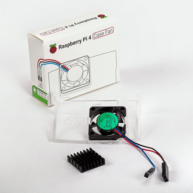
Designed for overclockers and other power users, this fan keeps your Raspberry Pi 4 at a comfortable operating temperature even under heavy load. The temperature-controlled fan delivers up to 1.4 CFM of airflow over the processor, memory, and power management IC. The bundled heatsink (18 x 8 x 10 mm) with self-adhesive pad improves heat transfer from the processor. The Raspberry Pi 4 Case Fan works with Raspberry Pi 4 and the official Raspberry Pi 4 case.
The Raspberry Pi Bumper is a snap-on silicone cover that protects the bottom and edges of the Raspberry Pi 5.
Features
One-piece flexible silicone rubber bumper
Enables easy access to the power button
Mounting holes remain accessible underneath the bumper
Downloads
Datasheet
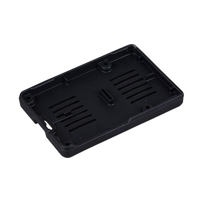
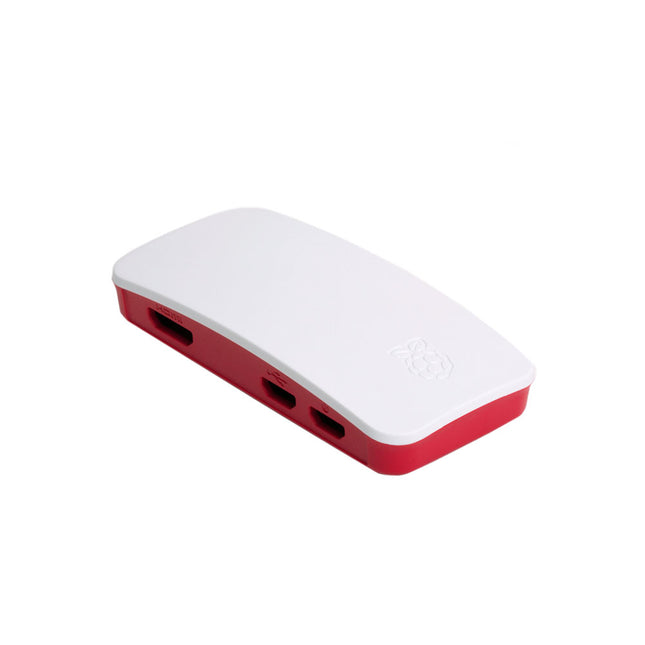
The case consists of two parts. It has a standard base featuring a cut-out to allow access to the GPIO, and a choice of three lids: a plain lid, a GPIO lid (allowing access to the GPIO from above), and a camera lid (which, when used with the short camera cable supplied, allows the Raspberry Pi Camera or Camera Noir to be fitted neatly inside it).
Included
1x base
3x lids (plain, GPIO, camera)
1x short camera cable
4x rubber feet