Search results for "ethernet OR module OR usr OR tcp232 OR t"
-
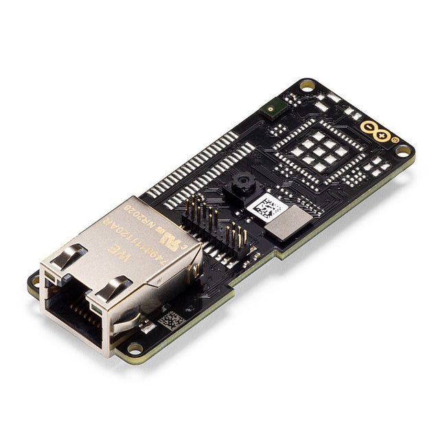
Arduino Arduino Pro Portenta Vision Shield (Ethernet)
The Arduino Pro Portenta Vision Shield brings industry-rated features to your Portenta. This hardware add-on will let you run embedded computer vision applications, connect wirelessly or via Ethernet to the Arduino Cloud or your own infrastructure, and activate your system upon the detection of sound events. Features 324x324 pixels camera sensor: use one of the cores in Portenta to run image recognition algorithms using the OpenMV for Arduino editor 100 Mbps Ethernet connector: get your Portenta H7 connected to the wired Internet 2 onboard microphones for directional sound detection: capture and analyse sound in real-time JTAG connector: perform low-level debugging of your Portenta board or special firmware updates using an external programmer SD-Card connector: store your captured data in the card, or read configuration files The Vision Shield has been designed to fit on top of the Arduino Portenta family. The Portenta boards feature multicore 32-bit ARM Cortex processors running at hundreds of megahertz, with megabytes of program memory and RAM. Portenta boards come with WiFi and Bluetooth. Embedded Computer Vision Made Easy Arduino has teamed up with OpenMV to offer you a free license to the OpenMV IDE, an easy way into computer vision using MicroPython as a programming paradigm. Download the OpenMV for Arduino Editor from our professional tutorials site and browse through the examples we have prepared for you inside the OpenMV IDE. Companies across the whole world are already building their commercial products based on this simple-yet-powerful approach to detect, filter, and classify images, QR codes, and others. Debugging With Professional Tools Connect your Portenta H7 to a professional debugger through the JTAG connector. Use professional software tools like the ones from Lauterbach or Segger on top of your board to debug your code step by step. The Vision Shield exposes the required pins for you to plug in your external JTAG. Camera Himax HM-01B0 camera module Resolution 320 x 320 active pixel resolution with support for QVGA Image sensor High sensitivity 3.6μ BrightSense pixel technology Microphone 2 x MP34DT05 Length 66 mm Width 25 mm Weight 11 gr For more information, check out the tutorials provided by Arduino here.
€ 69,95€ 27,98
Best Price
-

Würth Abc of Power Modules (E-book)
Functionality, structure and handling of a power module For readers with first steps in power management the “Abc of Power Modules” contains the basic principles necessary for the selection and use of a power module. The book describes the technical relationships and parameters related to power modules and the basis for calculation and measurement techniques. Contents Basics This chapter describes the need of a DC/DC voltage converter and its basic functionality. Furthermore, various possibilities for realizing a voltage regulator are presented and the essential advantages of a power module are mentioned. Circuit topologies Circuit concepts, buck and boost topologies very frequently used with power modules are explained in detail and further circuit topologies are introduced. Technology, construction and regulation technology The mechanical construction of a power module is presented, which has a significant influence on EMC and thermal performance. Furthermore, control methods are explained and circuit design tips are provided in this chapter. Measuring methods Meaningful measurement results are absolutely necessary to assess a power module. The relevant measurement points and measurement methods are described in this chapter. Handling The aspects of storage and handling of power modules are explained, as well as their manufacturing and soldering processes. Selection of a power modules Important parameters and criteria for the optimal selection of a power module are presented in this section.
€ 8,99
Members: € 7,19
-
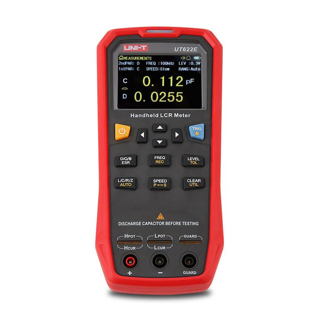
Uni-Trend UNI-T UT622E LCR Meter
The UT622E handheld LCR meter features powerful functions, high accuracy, fast speed, and long standby time. With a clear and intuitive 2.8-inch TFT LCD display, large-capacity rechargeable battery, and 100 kHz test frequency, the meter can be used for longstanding accurate and convenient measurement in any occasion. It is suitable for the measurement and screening of inductance, capacitance, and resistance in laboratories, production lines, maintenance points, etc. Features Max. test frequency: 100 kHz Accuracy: 0.1% Display count: 99999 Max. test rate: 20 times/s DCR: Yes Connectivity: Mini-USB Display: 2.8" TFT LCD Specifications Testfrequency 100 Hz, 120 Hz, 1 kHz, 10 kHz, 100 kHz Test level 0.1 Vmrs, 0.3 Vrms, 1 Vrms Output impedance 100 Ω Measurement parameters Primary: L/C/R/Z/DCRSecondary: D/Q/Θ/ESR DSR speed test Fast (20 times/s), medium (5 times/s), or slow (2 times/s) Range Auto/Hold Tolerance range 1%~20% Equivalent mode Series/Parallel Clearing connection Open/Short circuit Fuse of test ports 0.1 A/250 V Communication interface Mini-USB MAX reading of primary parameters 99999 MIN resolution 0.0001 Maximum accuracy 0.10% L 0.00 µH~99.999 H C 0.00 pF~99.999 mF Z/R 0.0000 Ω~9.9999 MΩ ESR 0.0000 Ω~999.99 Ω D 0.0000~9.9999 Q 0.0000~99999 Θ -179.9°~179.9° DCR 0.01 mΩ~20.000 MΩ Power supply 3.7 V/1800 mAh lithium polymer battery Display 2.8" TFT LCD (320x240) Dimensions 93 x 192 x 44 mm Weight 420 g Included UT622E LCR meter Short circuit board Four-terminal kelvin test leads USB cable Manual Downloads Datasheet Manual Software
€ 325,49
-
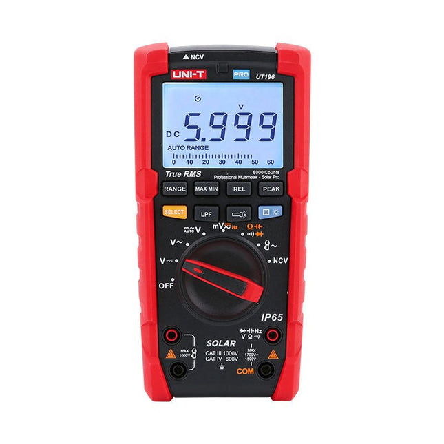
Uni-Trend UNI-T UT196 True RMS Solar Multimeter
The UT196 True RMS solar multimeter is an ideal tool for solar power system maintenance. This rugged meter is designed for technicians who work in rugged outdoor environments. UT196 can measure up to 1700 V DC and 1500 V AC voltages, and 3000 A AC current with an external current clamp sensor. This solar meter offers IP65 protection and able to withstand 2 m drop as well. The UT196 solar multimeter is designed with 1700 V DC, 1500 Vrms AC overload protection and tested for safe usage in CAT III 1000 V, CAT IV 600 V environments. Features True RMS Measure up to 1700 V DC and 1500 V AC for high voltage applications e.g. solar array, wind IP65 protection CAT III 1000V, CAT IV 600 V Analog bar Frequency response: 45 Hz~1 kHz Low-pass filter function Low impedance mode Built-in flashlight, bright backlight and visual alarm Applications High DC voltage measurement Output voltage and frequency measurement Voltage and frequency measurement Current and frequency measurement Specifications Range UT196 DC voltage (V) 1700 V ±0.2% +5 AC voltage (V) 1500 V ±0.8% +3 Frequency (Hz) 1 MHz ±0.08% +4 Resistance (Ω) 60 MΩ ±0.8% +2 Capacitance (F) 60 mF ±1.9% +5 Power 9 V battery Dimensions 195 x 95 x 58 mm Included UT196 Solar Multimeter Battery Test leads Downloads Datasheet Manual
€ 129,63
-

Uni-Trend UNI-T UT8803E True RMS Multimeter
The UT8803E is a portable, AC-powered 3⅚ digital multimeter with 6000 counts with automatic measuring range and large display with backlight. The UT8803E can be used to measure AC/DC voltage, AC/DC current, resistance, frequency, capacitance, inductance, triode (HFE), diode (LED), thyristor (SCR), and on-off switching. Features Extreme value and reference value operation, with analog bargraph Multiple measurement parameters optional D/Q parameters of capacitance and inductance can be measured Measurement resolution 3.5-inch, maximum measurement value 5999 Specifications Measurement Resolution 3⅚, Maximum Measurement Value 5999 Measurement Rate 2-3 measurements/s DC Voltage Range 600 mV~1000 V DC Current Range 600 µA~20 A AC Voltage Range 600 mV~750 V (True RMS) AC Current Range 600 µA~20 A (True-RMS) Resistance Range 600 Ω~60 MΩ Capacitance Range 6 nF~60 mF Inductance Range 600 µH~100 H Frequency Measurement Range 600 Hz~20 MHz Duty Cycle Measurement Range 5%~95% Mathematical Operation Maximum, minimum, relative value, trend chart Interface USB device (can be connected to the upper computer control software) Frequency response 100 KHz Downloads Datasheet User Manual Programming Manual Software
€ 192,39
-

Uni-Trend UNI-T UPO1202CS 2-ch Oscilloscope (200 MHz)
UNI-T UPO1202CS is a multifunctional, low-cost 2-channel digital phosphor oscilloscope with 200 MHz bandwidth and 1 GSa/s sampling rate. It can be widely used in the fields of electronic and electrical design, debugging, education and industrial design. UPO1000CS series adopts parallel digital signal processing technology, which greatly improves the data processing speed and waveform capture rate. The original Ultra Phosphor technology can present the cumulative effect of the tested signal as a multi-layered afterglow. Compared with traditional digital storage oscilloscopes, the persistence of digital phosphor oscilloscopes can present three-dimensional waveform data of amplitude, time and signal intensity. Fast Acquire technology can accurately capture abnormal events such as video, jitter, noise and runt signals. Specifications UPO1102CS UPO1202CS Bandwidth 100 MHz 200 MHz Analog channels 2 2 Sampling rate 1 GSa/s 1 GSa/s Storage depth 56 Mpts per channel 56 Mpts per channel Rise time ≤3.5ns ≤1.8ns Capture rate 500,000 wfms/s 500,000 wfms/s Waveform record 100,000 frames 100,000 frames Features 7' WVGA (800 x 480) TFT LCD Ultra Phosphor super fluorescent display effect, up to 256 levels of gray display Support RS232, I²C, SPI, CAN and LIN trigger Innovative RS232, I²C, SPI, CAN and LIN hardware decoding Vertical scale: 1 mV/div-20 V/div Low background noise: <100 μVrms 1M points enhanced FFT function. Support frequency setting, waterfall diagram, detection setting and marker measurement etc 36 kinds of waveform parameters can be automatically measured Rich trigger functions (edge, pulse width, video, slope, runt, overshoot, delay, timeout, duration, setup and hold, Nth edge and pattern trigger) Multi-Scopes support dual-channel independent trigger fluorescence display Multi-channel independent 7-bit hardware frequency counter DVM supports dual-channel independent AC and DC true RMS measurement Waveform arithmetic functions (FFT, +, -, ×, ÷, digital filtering, logic operations, and advanced operations) Rich interfaces: USB Host, USB Device, LAN, EXT Trig, AUX Out (Trig Out, Pass/Fail) Support SCPI programmable instrument standard command Support WEB access and control Downloads Datasheet Programming Manual User's Manual Quick Start Guide Software
€ 369,00
-
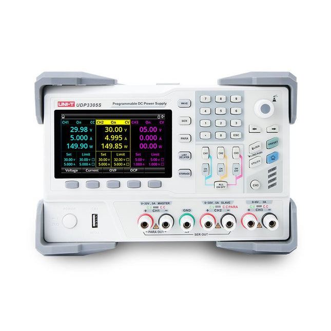
Uni-Trend UNI-T UDP3305S-E DC Power Supply (328 W)
The UDP3305S-E is a high-performance programmable linear DC power supply. It has a clear LCD user interface, excellent performance indicators, a variety of analysis functions and communication interfaces. It can meet the diversified test needs of users. It aims to provide cost-effective DC programmable power supply equipment for teaching, scientific research, industry and other fields. LCD interactive interface Using a 4.3-inch high-definition display screen, it provides users with a man-machine interface with rich functions and simple operation, which can display the current set output voltage/current, actual output voltage/current and protection output voltage/current value of the power supply in real time. The functional interface is simple and comprehensive, easy to operate. One-key setting for series and parallel The series-parallel connection between CH1 and CH2 of the main channel can be realized without external connection, which simplifies the connection and makes the test easier. List/Delayer function With list and delay setting functions, it can set up to 2048 sets of data according to test requirements, and the number of cycles can reach 99999. It is used with waveform templates, which is very convenient for cycle testing and aging testing. Rich remote control interface Standard RS232 communication interface, Ethernet interface, Digital I/O and master and slave USB interfaces, can be controlled by remote connection to Ethernet, or through RS232 and USB, with the host computer software to achieve software control. Specifications Type Linear DC power supply Channels 4 Total power 328 W Output voltage CH1/CH2: 0~30 VCH3: 0~6 VCH4: 5 V Output current CH1/CH2: 0~5 ACH3: 0~3 ACH4: 2 A Resolution 10 mV, 1 mA Setting accuracy 0.3% +20 mV<0.2% +5 mA Connectivity USB Device, RS-232, LAN, USB host, Digital I/O Included 1x UDP3305S-E DC Power Supply 1x Power cord 1x USB cable Downloads Datasheet User manual Programming manual Software V1.0 Firmware V1.10
€ 396,54
-
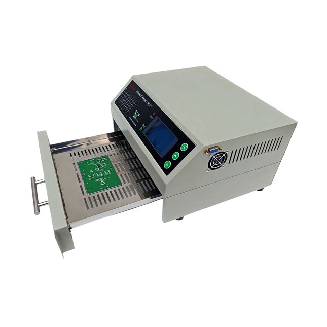
puhui Upgraded T-962 v2.0 Reflow Soldering Oven (Elektor Version)
This upgraded version 2.0 (available exclusively from Elektor) contains the following improvements: Enhanced protective earthing (PE) for furnace chassis Extra thermal insulation layer around furnace to reduce odors Connection to a computer, allowing curve editing on a PC Features such as constant temperature control and timing functions The infrared IC heater T-962 v2.0 is a microprocessor-controlled reflow oven that you can use for effectively soldering various SMD and BGA components. The whole soldering process can be completed automatically and it is very easy to use. This machine uses a powerful infrared emission and circulation of the hot air flow, so the temperature is being kept very accurate and evenly distributed. A windowed drawer is designed to hold the work-piece, and allows safe soldering techniques and the manipulation of SMDBGA and other small electronic parts mounted on a PCB assembly. The T-962 v2.0 may be used to automatically rework solder to correct bad solder joints, remove/replace bad components and complete small engineering models or prototypes. Features Large infrared soldering area Effective soldering area: 180 x 235 mm; this increases the usage range of this machine drastically and makes it an economical investment. Choice of different soldering cycles Parameters of eight soldering cycles are pre defined and the entire soldering process can completed automatically from Preheat, Soak and Reflow through to cool down. Special heat up and temperature equalization with all designs Uses up to 800 Watts of energy efficient Infrared heating and air circulation to re-flow solder. Ergonomic design, practical and easily operated Good build quality but at the same time light weight and a small footprint allows the T-962 v2.0 to be easily bench positioned transported or stored. Large number of available functions The T-962 v2.0 can solder most small parts of PCB boards, for example CHIP, SOP, PLCC, QFP, BGA etc. It is the ideal rework solution from single runs to on-demand small batch production. Specifications Soldering area (max) 180 x 235 mm (7.1 x 9.3") Power (max) 800 W Temperature range 0-280°C (32-536°F) Heating method Infrared Processing time 1~8 minutes Power supply 220 V AC/50 Hz Display LCD with Backlight Control mode 8 intelligent temperature curves Dimensions 310 x 290 x 170 mm (12.2 x 11.4 x 6.7") Weight 6.2 kg Included 1x T-962 v2.0 Reflow Soldering Oven (Elektor Version) 1x USB Stick (with Manual and Software) 2x Fuses 1x Power cord (EU) Downloads Manual
€ 289,00€ 249,00
Best Price
-

tinySA tinySA Ultra+ ZS407 Spectrum Analyzer
The tinySA Ultra+ ZS-407 is a compact, handheld spectrum analyzer and signal generator. Covering 100 kHz to 7.3 GHz in Ultra mode, it lets you visualize and analyze RF signals from HF right through many modern wireless bands – and can even spot signals up to ~12 GHz thanks to harmonic tracking. The intuitive 4-inch resistive touchscreen and rechargeable battery make it great for fieldwork, while features like a built-in signal generator, switchable bandpass filters, step attenuator, USB-PC control and auto-calibration add serious versatility. Features Screen size: 4 inch (480 x 320) Spectrum Analyzer for 0.1-900 MHz or, with Ultra mode enabled up to 7.3 GHz, level calibrated up to 7.3 GHz. Can observe signals up to 12 GHz Signal Generator with sine wave output between 0.1-900 MHz or square wave up to 6.3 GHz or RF test signal output up to 7.3 GHz when not used as Spectrum Analyzer. Switchable resolution bandpass filters from 200 Hz to 850 kHz Built-in 20 dB optional LNA Color display showing max 450 points providing gapless covering up to the full frequency range. MicroSD card slot for storing measurements, settings and screen captures. Specifications (Spectrum Analyzer) Input frequency range from 100 kHz to 900 MHz in normal mode and up to 7.3 GHz with ULTRA mode enabled Input impedance 50 ohm when input attenuation set to 10 dB or more. Selectable manual and automatic input attenuation between 0 dB and 31 dB in 1 dB steps when LNA not active Maximum +/-5V DC input Absolute maximum input level of +6 dBm with 0 dB internal attenuation Absolute maximum short term peak input power of +20 dBm with 30 dB internal attenuation Suggested maximum input power of +0 dBm with internal attenuation in automatic mode For best measurements keep input power below -25 dBm Input Intercept Point of third order modulation products (IIP3) of +15 dBm with 0 dB internal attenuation 1 dB compression point at -1 dBm with 0 dB internal attenuation Power detector resolution of 0.5 dB and linearity versus frequency of ±2 dB below 5.3 GHz, ±5dB between 5.3 GHz and 6 GHz Minimum burst length for correct level measurement at 850 kHz RBW in zero span mode of 50 microseconds Absolute power level accuracy after power level calibration of ±2 dB Built-in optional 20 dB LNA with Noise Figure of 5 dB up to 6 GHz Lowest discernible signal without LNA at 30 MHz using a resolution bandwidth of 30 kHz of -102 dBm Lowest discernible signal with LNA at 30 MHz using a resolution bandwidth of 200 Hz of -145 dBm Frequency accuracy equal to the selected resolution bandwidth Phase noise at 30 MHz of -108 dB/Hz at 100 kHz offset and -115 dB/Hz at 1MHz offset Spur free dynamic range when using a 30 kHz resolution bandwidth of 70 dB Resolution filters with a width of 0.2, 1, 3, 10, 30, 100, 300, 600 and 850 kHz On screen resolution of 51, 101, 145, 290 or 450 measurement points. Scanning speed of over 1000 points/second using largest resolution filters. Automatic optimization of actual scanning points to ensure coverage of the whole scan range regardless of the chosen resolution bandwidth Spur suppression option for assessing if certain signals are internally generated or actually present in the input signal Headphone output for listening to the demodulated audio (AM only). Stereo connector with or without microphone, high impedance is louder, short protected Specifications (Signal Generator) Sine wave output with harmonics below -40 dB of fundamental from 100 kHz to 900 MHz Output level selectable in 1 dB steps between -115 dBm and -19 dBm Above 800 MHz choice of two output modes: Cleanest signal mode: square wave, up to 6 GHz with coarse frequency steps and less accurate output level Highest accuracy mode: reduced harmonics with possibly strong spurs up to 7.3 GHz with frequency resolution equal to below 800 MHz and fine output level steps Level accuracy ±2 dB up to 800 MHz between -72 dBm and -19 dBm, less accuracy below -72 dBm, even less accuracy below -110 dBm Output frequency resolution 57.2 Hz Optional AM or FM modulation frequencies between 50 Hz and 5 kHz (AM) or 1 kHz (FM) or sweep over selectable frequency span AM modulation depth between 10% and 100% FM deviation between 1 kHz and 300 kHz Optional output level sweep over maximum the entire output level range Included 1x tinySA Ultra+ ZS407 Spectrum Analyzer 2x SMA connection cables 1x Barrel connector 1x Antenna with SMA connector 1x USB-C cable 1x microSD card (32 GB) Downloads Wiki
€ 196,02
-

iFixit iFixit Pro Tech Toolkit
The Pro Tech Toolkit is the one thing every DIYer, fixer, hacker, hobbyist, and professional needs to tackle any job. Every tool in the Pro Tech Toolkit has been re-engineered to be better. From the 64 Bit Driver Kit to the iFixit Opening Picks, every tool is specially designed and selected to maximize your repair capabilities. At the core of this kit is the iFixit 64 Bit Driver Kit, designed with extensive research into what fastener types are currently used in the consumer electronics industry and which legacy fasteners are still in demand by consumers. From the Apple Watch with its new tiny Tri-Point screws to vintage Nintendo game consoles with gamebit fasteners, the 64 bit kit covers them all with the highest quality CNC machined bits. Even the sturdy case was carefully engineered, having no hinges or latches to break, and features a sorting tray inside the magnetically attached lid. High-Performance Toolkit for DIY Repairs The perfect toolkit for pros to average joes. Contains all the poking, prying, gripping, lifting, ESD safety, and screw driving tools needed to service consumer electronics. Completely re-engineered to provide all the tools that you need, and none that you don't. Included Anti-Static Wrist Strap – protection for circuits against static electricity Small Suction Handle – suction handle for holding onto things lacking handles 3x iFixit Opening Tool – soft plastic prying tools 6x iFixit Opening Picks – thin prying tool for opening electronic devices Nylon Tipped Reverse Tweezers – to elevate and hold your work Angled ESD Tweezers – ESD-safe, feature teeth for tougher grip Blunt ESD Tweezers – ESD-safe, feature teeth for tougher grip Standard Spudger – tough antistatic tool for a variety of purposes Halberd Spudger – features a hook for scooping, scraping, pulling, and guiding.ESD-safe. Metal Spudger – for more powerful prying, scraping, probing, and poking action Jimmy – handy tool for 'Jimmy'ing open electronics. Magnetic Pad – Holds tiny screws and parts during repairs Tool Roll – Durable and compact Mako Precision Bit Set – all the bits needed for repairs on small electronics Mako Precision Bit Set Includes 64 Bit Driver 150 mm Flex Extension 4 mm Screwdriver Bits Phillips – 000, 00, 0, 1, 2 Flathead – 1, 1.5, 2, 2.5, 3, 4 mm Torx – T2, T3, T4, T5 Torx Security – TR6, TR7, TR8, TR9, TR10, TR15, TR20, TR25 Pentalobe – P2, P5, P6 JIS – J000, J00, J0, J1 Hex – 0.7, 0.9, 1.3, 1.5, 2, 2.5, 3, 3.5, 4, 4.5, 5 mm Tri-point – Y000, Y00, Y0, Y1 Nut Driver – 2.5, 3, 3.5, 4, 4.5, 5, 5.5 mm Square – 1, 2 Gamebit – 3.8, 4.5 mm Spanner – 6, 8 Triangle – 2, 3 mm Standoff Bit for iPhone Oval Bit Magnetic Pickup Bit SIM Eject Bit 1/4" to 4 mm Driver Adapter
€ 69,95
-
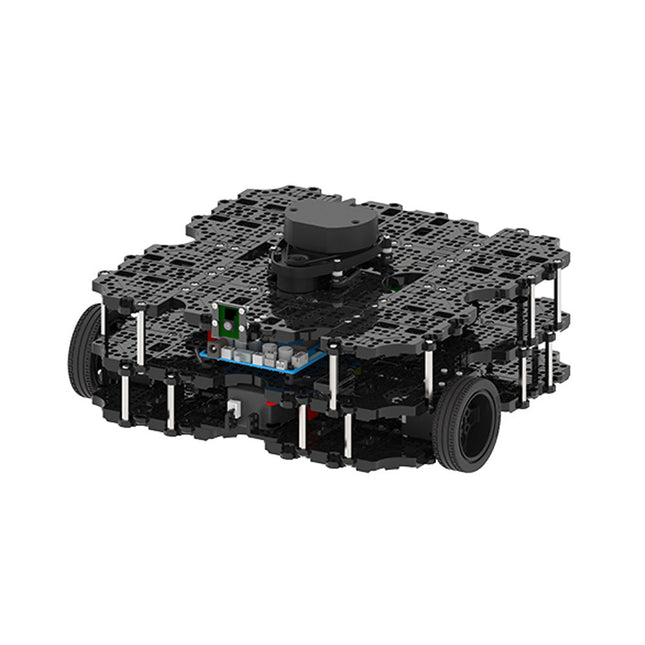
Robotis Robotis TurtleBot3 Waffle Pi (incl. Raspberry Pi 4)
World’s Most Popular ROS Platform TurtleBot is the most popular open source robot for education and research. The new generation TurtleBot3 is a small, low cost, fully programmable, ROS based mobile robot. It is intended to be used for education, research, hobby and product prototyping. Affordable Cost TurtleBot was developed to meet the cost-conscious needs of schools, laboratories and companies. TurtleBot3 is the most affordable robot among the SLAM-able mobile robots equipped with a 360° Laser Distance Sensor LDS-01. ROS Standard The TurtleBot brand is managed by Open Robotics, which develops and maintains ROS. Nowadays, ROS has become the go-to platform for all the roboticists around the world. TurtleBot can be integrated with existing ROS-based robot components, but TurtleBot3 can be an affordable platform for whom want to get started learning ROS. Extensibility TurtleBot3 encourages users to customize its mechanical structure with some alternative options: open source embedded board (as a control board), computer and sensors. TurtleBot3 Waffle Pi is a two-wheeled differential drive type platform but it is able to be structurally and mechanically customized in many ways: Cars, Bikes, Trailers and so on. Extend your ideas beyond imagination with various SBC, sensors and motors on a scalable structure. Modular Actuator for Mobile Robot TurtleBot3 is able to get a precise spatial data by using 2 DYNAMIXEL’s in the wheel joints. DYNAMIXEL XM series can be operated by one of 6 operating modes (XL series: 4 operating modes): Velocity control mode for wheels, Torque control mode or Position control mode for joint, etc. DYNAMIXEL can be used even to make a mobile manipulator which is light but can be precisely controlled with velocity, torque and position control. DYNAMIXEL is a core component that makes TurtleBot3 perfect. It is easy to assemble, maintain, replace and reconfigure. Open Control Board for ROS The control board is open-sourced in hardware wise and in software wise for ROS communication. The open source control board OpenCR1.0 is powerful enough to control not only DYNAMIXEL’s but also ROBOTIS sensors that are frequently being used for basic recognition tasks in cost effective way. Various sensors such as Touch sensor, Infrared sensor, Color sensor and a handful more are available. The OpenCR1.0 has an IMU sensor inside the board so that it can enhance precise control for countless applications. The board has 3.3 V, 5 V, 12 V power supplies to reinforce the available computer device lineups. Open Source The hardware, firmware and software of TurtleBot3 are open source which means that users are welcomed to download, modify and share source codes. All components of TurtleBot3 are manufactured with injection molded plastic to achieve low cost, however, the 3D CAD data is also available for 3D printing. Specifications Maximum translational velocity 0.26 m/s Maximum rotational velocity 1.82 rad/s (104.27 deg/s) Maximum payload 30 kg Size (L x W x H) 281 x 306 x 141 mm Weight (+ SBC + Battery + Sensors) 1.8 kg Threshold of climbing 10 mm or lower Expected operating time 2h Expected charging time 2h 30m SBC (Single Board Computers) Raspberry Pi 4 (2 GB RAM) MCU 32-bit ARM Cortex-M7 with FPU (216 MHz, 462 DMIPS) Remote Controller RC-100B + BT-410 Set (Bluetooth 4, BLE) Actuator XL430-W210 LDS (Laser Distance Sensor) 360 Laser Distance Sensor LDS-01 or LDS-02 Camera Raspberry Pi Camera Module v2.1 IMU Gyroscope 3 AxisAccelerometer 3 Axis Power connectors 3.3 V/800 mA5 V/4 A12 V/1 A Expansion pins GPIO 18 pinsArduino 32 pin Peripheral 3x UART, 1x CAN, 1x SPI, 1x I²C, 5x ADC, 4x 5-pin OLLO DYNAMIXEL ports 3x RS485, 3x TTL Audio Several programmable beep sequences Programmable LEDs 4x User LED Status LEDs 1x Board status LED1x Arduino LED1x Power LED Buttons and Switches 2x Push buttons, 1x Reset button, 2x Dip switch Battery Lithium polymer 11.1 V 1800 mAh / 19.98 Wh 5C PC connection USB Firmware upgrade via USB / via JTAG Power adapter (SMPS) Input: 100-240 VAC 50/60 Hz, 1.5 A @maxOutput: 12 VDC, 5 A Downloads ROS Robot Programming GitHub E-Manual Community
€ 1.879,00
Best Price


-
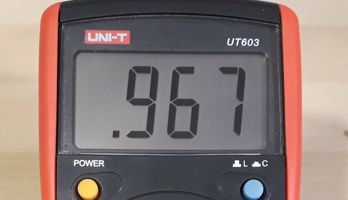
, by Jean-François Simon LCR Meter: The UNI-T UT603 (Review)
A few weeks ago we reviewed the DE-5000 LCR meter. This time, let’s take a look at the UT603 from UNI-T. Like the former, it’s...
