Search results for "esp3212 OR wi OR fi OR ble OR module"
-

Würth Abc of Power Modules (E-book)
Functionality, structure and handling of a power module For readers with first steps in power management the “Abc of Power Modules” contains the basic principles necessary for the selection and use of a power module. The book describes the technical relationships and parameters related to power modules and the basis for calculation and measurement techniques. Contents Basics This chapter describes the need of a DC/DC voltage converter and its basic functionality. Furthermore, various possibilities for realizing a voltage regulator are presented and the essential advantages of a power module are mentioned. Circuit topologies Circuit concepts, buck and boost topologies very frequently used with power modules are explained in detail and further circuit topologies are introduced. Technology, construction and regulation technology The mechanical construction of a power module is presented, which has a significant influence on EMC and thermal performance. Furthermore, control methods are explained and circuit design tips are provided in this chapter. Measuring methods Meaningful measurement results are absolutely necessary to assess a power module. The relevant measurement points and measurement methods are described in this chapter. Handling The aspects of storage and handling of power modules are explained, as well as their manufacturing and soldering processes. Selection of a power modules Important parameters and criteria for the optimal selection of a power module are presented in this section.
€ 8,99
Members: € 7,19
-
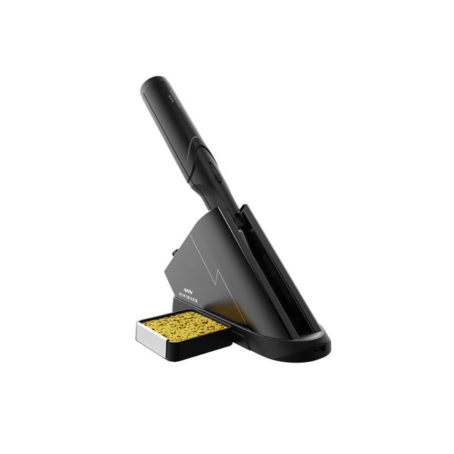
Miniware Miniware TS1C Cordless Soldering Station
The Miniware Cordless Soldering Station TS1C (with integrated OLED screen and Bluetooth) is an intelligent soldering tool that heats up to 400°C in less than 20 seconds. Thanks to the built-in battery, the wireless soldering pen sits comfortably in the hand and is easy to use. Features New high-efficiency supercapacitor energy storage technology, 10,000-level charge and discharge times Seperate design + true wireless, enjoy wireless soldering experience BLE4.2 Bluetooth communication technology to realize remote control and setting Standard PD2 20 V 45 W max power input, up to 36 W soldering power, can continuously solder more than 180 solder joints (0805) with a single full charge Control station preheating to improve heating efficiency 3 expansion slots for accessories Control Station Standard PD2 20 V 45 W max power input, over current safety protection 128x64 pixel OLED screen, display soldering pen status in real time Control station preheating, improve heating efficiency Remote control and setting: temperature regulating, menu setting, viewing device info and status, etc. Work as soldering stand and charging station 3 expansion slots for multiple expandable accessories like sponge slot Soldering Pen Built-in 750F high-efficiency energy storage supercapacitor, can be charged via control station (or via its USB Type-C interface in emergency cases) 36 W maximum heating power, can solder more than 180 solder joints (0805) continuously under a single full charge Compatible with Miniware 3.5 mm audio interface soldering tips (TS80/80P soldering tip series) Boost mode (holding the button on the pen) Included TS1C Soldering pen TS1C Control station Soldering tip (TS-B02) Silicone cable Sponge slot incl. sponge Manual
€ 168,19
-
Elektor Digital Raspberry Pi 5 Essentials (E-book)
Program, build, and master over 60 projects with Python The Raspberry Pi 5 is the latest single-board computer from the Raspberry Pi Foundation. It can be used in many applications, such as in audio and video media centers, as a desktop computer, in industrial controllers, robotics, and in many domestic and commercial applications. In addition to the well-established features found in other Raspberry Pi computers, the Raspberry Pi 5 offers Wi-Fi and Bluetooth (classic and BLE), which makes it a perfect match for IoT as well as in remote and Internet-based control and monitoring applications. It is now possible to develop many real-time projects such as audio digital signal processing, real-time digital filtering, real-time digital control and monitoring, and many other real-time operations using this tiny powerhouse. The book starts with an introduction to the Raspberry Pi 5 computer and covers the important topics of accessing the computer locally and remotely. Use of the console language commands as well as accessing and using the desktop GUI are described with working examples. The remaining parts of the book cover many Raspberry Pi 5-based hardware projects using components and devices such as LEDs and buzzers LCDs Ultrasonic sensors Temperature and atmospheric pressure sensors The Sense HAT Camera modules Example projects are given using Wi-Fi and Bluetooth modules to send and receive data from smartphones and PCs, and sending real-time temperature and atmospheric pressure data to the cloud. All projects given in the book have been fully tested for correct operation. Only basic programming and electronics experience are required to follow the projects. Brief descriptions, block diagrams, detailed circuit diagrams, and full Python program listings are given for all projects described.
€ 32,95
Members: € 26,36
-
Elektor Publishing Raspberry Pi 5 Essentials
Program, build, and master over 60 projects with Python The Raspberry Pi 5 is the latest single-board computer from the Raspberry Pi Foundation. It can be used in many applications, such as in audio and video media centers, as a desktop computer, in industrial controllers, robotics, and in many domestic and commercial applications. In addition to the well-established features found in other Raspberry Pi computers, the Raspberry Pi 5 offers Wi-Fi and Bluetooth (classic and BLE), which makes it a perfect match for IoT as well as in remote and Internet-based control and monitoring applications. It is now possible to develop many real-time projects such as audio digital signal processing, real-time digital filtering, real-time digital control and monitoring, and many other real-time operations using this tiny powerhouse. The book starts with an introduction to the Raspberry Pi 5 computer and covers the important topics of accessing the computer locally and remotely. Use of the console language commands as well as accessing and using the desktop GUI are described with working examples. The remaining parts of the book cover many Raspberry Pi 5-based hardware projects using components and devices such as LEDs and buzzers LCDs Ultrasonic sensors Temperature and atmospheric pressure sensors The Sense HAT Camera modules Example projects are given using Wi-Fi and Bluetooth modules to send and receive data from smartphones and PCs, and sending real-time temperature and atmospheric pressure data to the cloud. All projects given in the book have been fully tested for correct operation. Only basic programming and electronics experience are required to follow the projects. Brief descriptions, block diagrams, detailed circuit diagrams, and full Python program listings are given for all projects described.
€ 39,95
Members: € 35,96
-
Elektor Digital Raspberry Pi 3 – Basic to Advanced Projects (E-book)
This book is about the Raspberry Pi 3 computer and its use in various control and monitoring applications. The book explains in simple terms and with tested and working example projects, how to configure the Raspberry Pi 3 computer, how to install and use the Linux operating system, and how to write hardware based applications programs using the Python programming language. The nice feature of this book is that it covers many Raspberry Pi 3 based hardware projects using the latest hardware modules such as the Sense HAT, Swiss Pi, MotoPi, Camera module, and many other state of the art analog and digital sensors. An important feature of the Raspberry Pi 3 is that it contains on-board Bluetooth and Wi-Fi modules. Example projects are given in the book on using the Wi-Fi and the Bluetooth modules to show how real-data can be sent to the Cloud using the Wi-Fi module, and also how to communicate with an Android based mobile phone using the Bluetooth module. The book is ideal for self-study, and is intended for electronic/electrical engineering students, practising engineers, research students, and for hobbyists. It is recommended that the book should be followed in the given Chapter order. Over 30 projects are given in the book. All the projects in the book are based on the Python programming language and they have been fully tested. Full program listings of every project are given in the book with comments and full descriptions. Experienced programmers should find it easy to modify and update the programs to suit their needs. The following sub-headings are given for each project to make it as easy as possible for the readers to follow the projects: Project title Description Aim of the project Raspberry Pi type Block diagram Circuit diagram Program listing
€ 29,95
Members: € 23,96
-
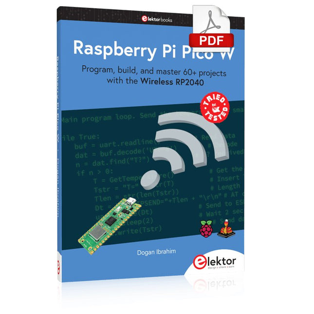
Elektor Digital Raspberry Pi Pico W (E-book)
Program, build, and master 60+ projects with the Wireless RP2040 The Raspberry Pi Pico and Pico W are based on the fast, efficient, and low-cost dual-core ARM Cortex M0+ RP2040 microcontroller chip running at up to 133 MHz and sporting 264 KB of SRAM and 2 MB of Flash memory. Besides spacious memory, the Pico and Pico W offer many GPIO pins, and popular peripheral interface modules like ADC, SPI, I²C, UART, PWM, timing modules, a hardware debug interface, and an internal temperature sensor. The Raspberry Pi Pico W additionally includes an on-board Infineon CYW43439 Bluetooth and Wi-Fi chipset. At the time of writing this book, the Bluetooth firmware was not yet available. Wi-Fi is however fully supported at 2.4 GHz using the 802.11b/g/n protocols. This book is an introduction to using the Raspberry Pi Pico W in conjunction with the MicroPython programming language. The Thonny development environment (IDE) is used in all of the 60+ working and tested projects covering the following topics: Installing the MicroPython on Raspberry Pi Pico using a Raspberry Pi or a PC Timer interrupts and external interrupts Analogue-to-digital converter (ADC) projects Using the internal temperature sensor and external sensor chips Using the internal temperature sensor and external temperature sensor chips Datalogging projects PWM, UART, I²C, and SPI projects Using Bluetooth, WiFi, and apps to communicate with smartphones Digital-to-analogue converter (DAC) projects All projects are tried & tested. They can be implemented on both the Raspberry Pi Pico and Raspberry Pi Pico W, although the Wi-Fi-based subjects will run on the Pico W only. Basic programming and electronics experience are required to follow the projects. Brief descriptions, block diagrams, detailed circuit diagrams, and full MicroPython program listings are given for all projects.
€ 34,95
Members: € 27,96
-
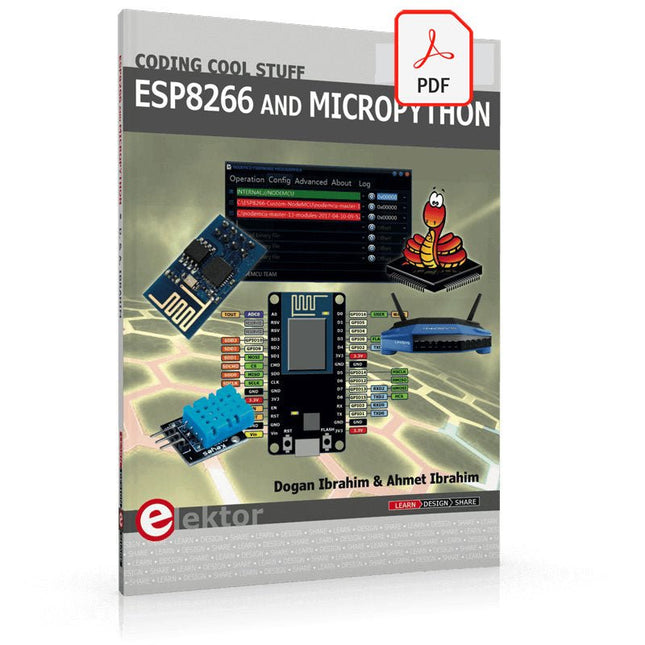
Elektor Digital ESP8266 and MicroPython (E-book)
Recently, the development of a tiny chip called the ESP8266 has made it possible to interface any type of microcontroller to a Wi-Fi AP. The ESP8266 is a low-cost tiny Wi-Fi chip having fully built-in TCP/IP stack and a 32-bit microcontroller unit. This chip, produced by Shanghai based Chinese manufacturer Espressif System, is IEEE 802.11 b/g/n Wi-Fi compatible with on-chip program and data memory, and general purpose input-output ports. Several manufacturers have incorporated the ESP8266 chip in their hardware products (e.g. ESP-xx, NodeMCU etc) and offer these products as a means of connecting a microcontroller system such as the Android, PIC microcontroller or others to a Wi-Fi. The ESP8266 is a low-power chip and costs only a few Dollars. ESP8266 and MicroPython – Coding Cool Stuff is an introduction to the ESP8266 chip and describes the features of this chip and shows how various firmware and programming languages such as the MicroPython can be uploaded to the chip. The main aim of the book is to teach the readers how to use the MicroPython programming language on ESP8266 based hardware, especially on the NodeMCU. Several interesting and useful projects are given in the e-book (pdf) to show how to use the MicroPython in NodeMCU type ESP8266 hardware: Project “What shall I wear today?”: You will be developing a weather information system using a NodeMCU development board together with a Text-to-Speech processor module. Project “The Temperature and Humidity on the Cloud”: You will be developing a system that will get the ambient temperature and humidity using a sensor and then store this data on the cloud so that it can be accessed from anywhere. Project “Remote Web Based Control”: You will be developing a system that will remotely control two LEDs connected to a NodeMCU development board using an HTTP Web Server application.
€ 29,95
Members: € 23,96


-
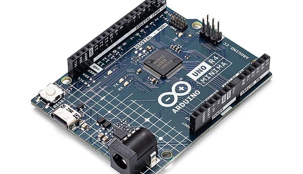
, by Clemens Valens Two New Arduino UNO R4 Boards: Minima and WiFi
The Arduino UNO R4 Minima and the Arduino UNO R4 WiFi have finally hit the shelves, introducing an exciting new chapter for Arduino enthusiasts and...
-

, by Jean-François Simon The RC-RICK-868-EV Wireless Modem: A Compelling Addition to Your Workbench
In this review, we're exploring the RC-RICK-868-EV, a specialized evaluation kit by Radiocontrolli designed for their RC-RICK-868 radio modem. This device stands out by employing...
-
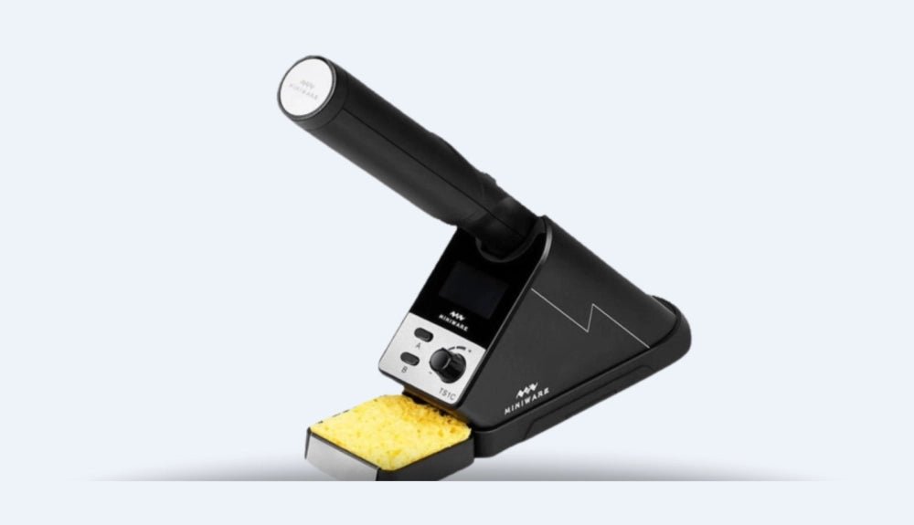
, by Günter Spanner Say Goodbye to Cables: Meet the Miniware TS1C Cordless Soldering Iron
The Miniware TS1C realizes every soldering enthusiast's dream: a cordless soldering iron that liberates you from the inconvenience of power cables. Yet, there's more to...
-
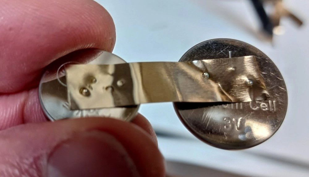
, by Clemens Valens Fix Battery Packs Like a Pro: Fnirsi SWM-10 Portable Spot Welder Review
In an era dominated by cordless tools, electric bikes, and various battery-powered devices, the ability to repair battery packs has become increasingly important. Spot welding,...
-
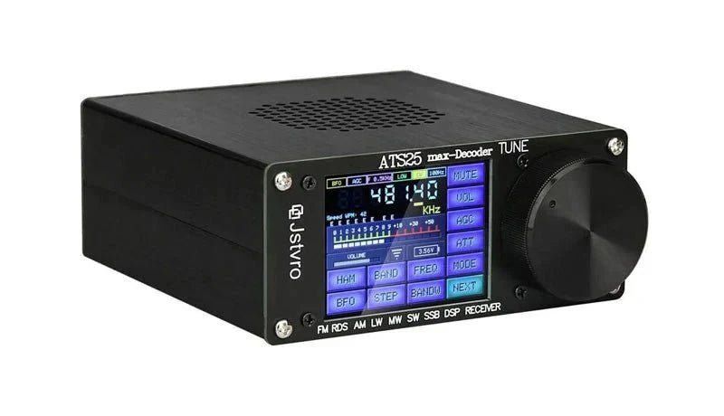
, by Jan Buiting Introducing the ATS25 Max: The Ultimate Ultra-Portable Decoder Receiver
Elektor proudly presents the ATS25 max-Decoder, a powerful yet ultra-compact multimode DSP receiver. This cutting-edge device offers comprehensive coverage of LW, SW, MW, FM, and...


