Pico Breakout Garden Base sits underneath your Pico and lets you connect up to six of our extensive selection of Pimoroni breakouts to it. Whether it's environmental sensors so you can keep track of the temperature and humidity in your office, a whole host of little screens for important notifications and readouts, and, of course, LEDs. Scroll down for a list of breakouts that are currently compatible with our C++/MicroPython libraries!As well as a labelled landing area for your Pico, there's also a full set of broken out Pico connections, in case you need to attach even more sensors, wires, and circuitry. We've thrown in some rubber feet to keep the base nice and stable and to stop it from scratching your desk, or there are M2.5 mounting holes at the corners so that you can bolt it onto a solid surface if you prefer.The six sturdy black slots are edge connectors that connect the breakouts to the pins on your Pico. There's two slots for SPI breakouts, and four slots for I²C breakouts. Because I²C is a bus, you can use multiple I²C devices at the same time, providing they don't have the same I²C address (we've made sure that all of our breakouts have different addresses, and we print them on the back of the breakouts so they're easy to find).As well as being a handy way to add functionality to your Pico, Breakout Garden is also very useful for prototyping projects without the need for complicated wiring, soldering, or breadboards, and you can grow or change up your setup at any time.Features
Six sturdy edge-connector slots for breakouts
4x I²C slots (5 pins)
2x SPI slot (7 pins)
Landing area with female headers for Raspberry Pi Pico
0.1” pitch, 5 or 7 pin connectors
Broken-out pins
Reverse polarity protection (built into breakouts)
99% assembled – just need to stick on the feet!
Compatible with Raspberry Pi Pico
Thanks to its six sturdy slots, Breakout Garden enables the users to simply plug and play with various tiny breakout board.
Just insert one or more boards into the slots in the Breakout Garden HAT and you’re ready to go. The mini breakouts feel secure enough in the edge-connector slots and are very unlikely to fall out.
There are a number of useful pins along the top of Breakout Garden, which lets you connect other devices and integrate them into your project.
You shouldn't be worried if you insert a board the wrong way thanks to provided reverse polarity protection. It doesn't matter which slot you use for each breakout either, because the I²C address of the breakout will be recognised by the software and it'll detect them correctly in case you move them around.
Features
Six sturdy edge-connector slots for Pimoroni breakouts
0.1” pitch, 5 pin connectors
Broken-out pins (1 × 10 strip of male header included)
Standoffs (M2.5, 10 mm height) included to hold your Breakout Garden securely
Reverse polarity protection (built into breakouts)
HAT format board
Compatible with Raspberry Pi 3 B+, 3, 2, B+, A+, Zero, and Zero W
It's suggested using the included standoffs to attache Breakout Garden to your Raspberry Pi.
Software
Breakout Garden doesn't require any software of its own, but each breakout you use will need a Python library. On the Breakout Garden GitHub page you'll find an automatic installer, which will install the appropriate software for a given breakout. There are also some examples that show you what else you can do with Breakout Garden.
Functionality, structure and handling of a power module
For readers with first steps in power management the “Abc of Power Modules” contains the basic principles necessary for the selection and use of a power module. The book describes the technical relationships and parameters related to power modules and the basis for calculation and measurement techniques.
Contents
Basics
This chapter describes the need of a DC/DC voltage converter and its basic functionality. Furthermore, various possibilities for realizing a voltage regulator are presented and the essential advantages of a power module are mentioned.
Circuit topologies
Circuit concepts, buck and boost topologies very frequently used with power modules are explained in detail and further circuit topologies are introduced.
Technology, construction and regulation technology
The mechanical construction of a power module is presented, which has a significant influence on EMC and thermal performance. Furthermore, control methods are explained and circuit design tips are provided in this chapter.
Measuring methods
Meaningful measurement results are absolutely necessary to assess a power module. The relevant measurement points and measurement methods are described in this chapter.
Handling
The aspects of storage and handling of power modules are explained, as well as their manufacturing and soldering processes.
Selection of a power modules
Important parameters and criteria for the optimal selection of a power module are presented in this section.
The flexibility of the Artemis module starts with SparkFun's Arduino core. You can program and use the Artemis module just like you would an Uno or any other Arduino. The time to first blink is just 5 minutes away! We built the core from the ground up, making it fast and as lightweight as possible.
Next is the module itself. Measuring 10 x 15 mm, the Artemis module has all the support circuitry you need to use the fantastic Ambiq Apollo3 processor in your next project. We're proud to say the SparkFun Artemis module is the first open-source hardware module with the design files freely and easily available. We've carefully designed the module so that implementing Artemis into your design can be done with low-cost 2-layer PCBs and 8mil trace/space.
Made in the USA at SparkFun's Boulder production line, the Artemis module is designed for consumer-grade products. This truly differentiates the Artemis from its Arduino brethren. Ready to scale your product? The Artemis will grow with you beyond the Uno footprint and Arduino IDE. Additionally, the Artemis has an advanced HAL (hardware abstraction layer), allowing users to push the modern Cortex-M4F architecture to its limit.
The SparkFun Artemis Module is fully FCC/IC/CE certified and is available in full tape and reel quantities. With 1M flash and 384k RAM, you'll have plenty of room for your code. The Artemis module runs at 48MHz with a 96MHz turbo mode available and with Bluetooth to boot!
Specifications
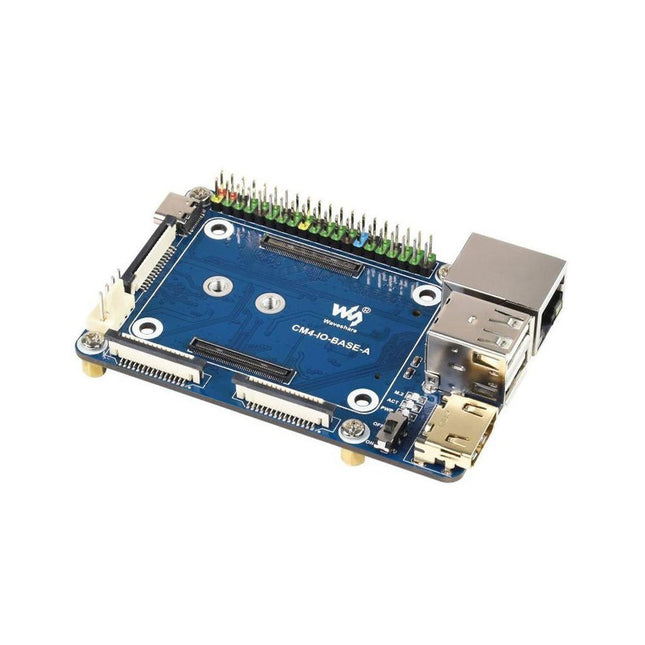
CM4 socket
Suitable for all variants of Compute Module 4
Networking
Gigabit Ethernet RJ45 connectorM.2 M KEY, supports communication modules or NVME SSD
Connector
Raspberry Pi 40-PIN GPIO header
USB
2x USB 2.0 Type A2x USB 2.0 via FFC connector
Display
MIPI DSI display port (15-pin 1.0 mm FPC connector)
Camera
2x MIPI CSI-2 camera port (15-pin 1.0 mm FPC connector)
Video
2x HDMI port (including one port via FFC connector), supports 4K 30fps output
RTC
N/A
Storage
MicroSD card socket for Compute Module 4 Lite (without eMMC) variants
Fan header
No fan control, 5 V
Power input
5 V
Dimensions
85 x 56 mm
Included
1x CM4-IO-BASE-A
1x SSD mounting screw
Downloads
Wiki
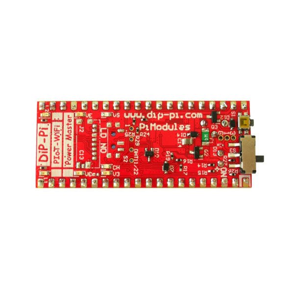
The DiP-Pi Power Master is an Advanced Powering System with embedded sensors interfaces that cover most of possible needs for application based on Raspberry Pi Pico. It can supply the system with up to 1.5 A @ 4.8 V delivered from 6-18 VDC on various powering schemes like Cars, Industrial plant etc., additionally to original micro-USB of the Raspberry Pi Pico. It supports LiPo or Li-Ion Battery with Automatic Charger as also automatic switching from cable powering to battery powering or reverse (UPS functionality) when cable powering lost. Extended Powering Source (EPR) is protected with PPTC Resettable fuse, Reverse Polarity, as also ESD.
The DiP-Pi Power Master contains Raspberry Pi Pico embedded RESET button as also ON/OFF Slide Switch that is acting on all powering sources (USB, EPR or Battery). User can monitor (via Raspberry Pi Pico A/D pins) battery level and EPR Level with PICO’s A/D converters. Both A/D inputs are bridged with 0402 resistors (0 OHM) therefore if for any reason user needs to use those Pico pins for their own application can be easy removed. The charger is automatically charging connected battery (if used) but in addition user can switch charger ON/OFF if their application needs it. DiP-Pi Power Master can be used for cable powered systems, but also for pure Battery Powered System with ON/OFF. Each powering source status is indicated by separate informative LEDs (VBUS, VSYS, VEPR, CHGR, V3V3).
User can use any capacity of LiPo or Li-Ion type; however, must take care to use PCB protected batteries with max discharge current allowed of 2 A. The embedded battery charger is set to charge battery with 240 mA current. This current is set by resistor so if user need more/less can himself to change it.
In Addition to all above features DiP-Pi Power Master is equipped with embedded 1-wire and DHT11/22 sensors interfaces. Combination of the extended powering, battery, and sensors interfaces make the DiP-Pi Power Master ideal for applications like data logger, plants monitoring, refrigerators monitoring etc.
DiP-Pi Power Master is supported with plenty of ready to use examples written in Micro Python or C/C++.
Specifications
General
Dimensions 21 x 51 mm
Raspberry Pi Pico pinout compatible
Independent Informative LEDs (VBUS, VSYS, VEPR, CHGR, V3V3)
Raspberry Pi Pico RESET Button
ON/OFF Slide Switch acting on all powering sources (USB, EPR, Battery)
External Powering 6-18 V DC (Cars, Industrial Applications etc.)
External Power (6-18 VDC) Level Monitoring
Battery Level Monitoring
Inverse Polarity Protection
PPTC Fuse Protection
ESD Protection
Automatic Battery Charger (for PCB protected LiPo, Li-Ion – 2 A Max) Automatic/User Control
Automatic Switch from Cable Powering to Battery Powering and reverse (UPS Functionality)
Various powering schemes can be used at the same time with USB Powering, External Powering and Battery Powering
1.5 A @ 4.8 V Buck Converter on EPR
Embedded 3.3 V @ 600mA LDO
Embedded 1-wire Interface
Embedded DHT-11/22 Interface
Powering Options
Raspberry Pi Pico micro-USB (via VBUS)
External Powering 6-18 V (via dedicated Socket – 3.4/1.3 mm)
External Battery
Supported Battery Types
LiPo with protection PCB max current 2A
Li-Ion with protection PCB max current 2A
Embedded Peripherals and Interfaces
Embedded 1-wire interface
Embedded DHT-11/22 Interface
Programmer Interface
Standard Raspberry Pi Pico C/C++
Standard Raspberry Pi Pico Micro Python
Case Compatibility
DiP-Pi Plexi-Cut Case
System Monitoring
Battery Level via Raspberry Pi Pico ADC0 (GP26)
EPR Level via Raspberry Pi Pico ADC1 (GP27)
Informative LEDs
VB (VUSB)
VS (VSYS)
VE (VEPR)
CH (VCHR)
V3 (V3V3)
System Protection
Direct Raspberry Pi Pico Hardware Reset Button
ESD Protection on EPR
Reverse Polarity Protection on EPR
PPTC 500 mA @ 18 V fuse on EPR
EPR/LDO Over Temperature protection
EPR/LDO Over Current protection
System Design
Designed and Simulated with PDA Analyzer with one of the most advanced CAD/CAM Tools – Altium Designer
Industrial Originated
PCB Construction
2 ozcopper PCB manufactured for proper high current supply and cooling
6 mils track/6 mils gap technology 2 layers PCB
PCB Surface Finishing – Immersion Gold
Multi-layer Copper Thermal Pipes for increased System Thermal Response and better passive cooling
Downloads
Datasheet
Datasheet
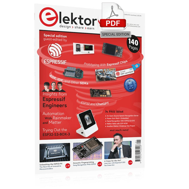
Elektor GREEN and GOLD members can download their digital edition here.
Not a member yet? Click here.
Accelerating IoT Innovation
A Color E-Ink Wi-Fi Picture Frame
ESP-Launchpad TutorialFrom Zero to Flashing in Minutes
ESP32 and ChatGPTOn the Way to a Self-Programming System…
Walkie-Talkie with ESP-NOWNot Quite Wi-Fi, Not Quite Bluetooth!
From Idea to Circuit with the ESP32-S3A Guide to Prototyping with Espressif Chips
AIoT Chip InnovationAn Interview With Espressif CEO Teo Swee-Ann
Simulate ESP32 with WokwiYour Project’s Virtual Twin
Trying Out the ESP32-S3-BOX-3A Comprehensive AIoT Development Platform
Electronics Workspace EssentialsInsights and Tips From Espressif Engineers
The ESP RainMaker StoryHow We Built “Your” IoT Cloud
Assembling the Elektor Cloc 2.0 KitAn Elektor Product Unboxed by Espressif
Unleashing the ESP32-P4The Next Era of Microcontrollers
Rust + EmbeddedA Development Power Duo
Who Are the Rust-Dacious Embedded Developers?How Espressif is Cultivating Embedded Rust for the ESP32
Espressif’s Series of SoCs
Building a PLC with Espressif SolutionsWith the Capabilities and Functionality of the ISOBUS Protocol
The ESP32-S3 VGA BoardBitluni’s Exciting Journey Into Product Design
Acoustic Fingerprinting on ESP32Song Recognition With Open-Source Project Olaf
Circular Christmas Tree 2023A High-Tech Way to Celebrate the Holiday Season
A Simpler and More Convenient LifeAn Amateur Project Based on the Espressif ESP8266 Module
How to Build IoT Apps without Software ExpertiseWith Blynk IoT Platform and Espressif Hardware
Building a Smart User Interface on ESP32
Quick & Easy IoT Development with M5Stack
Prototyping an ESP32-Based Energy Meter
A Value-Added Distributor for IoT and More
In-Depth Insights: Interview With Arduino on the Nano ESP32Alessandro Ranellucci and Martino Facchin Discuss Espressif Collaboration
Your AIoT Solution ProviderInsights From Espressif
Streamlining MCU Development With ESP-IDF Privilege Separation
An Open-Source Speech Recognition Server……and the ESP BOX
The Thinking EyeFacial Recognition and More Using the ESP32-S3-EYE
ESP32-C2-Based Coin Cell SwitchDesign and Performance Evaluation
The Smart Home Leaps Forward with MatterUnlocking Smart Home IoT Potential
Tech the Future: Where Is Smart Home IoT Headed?
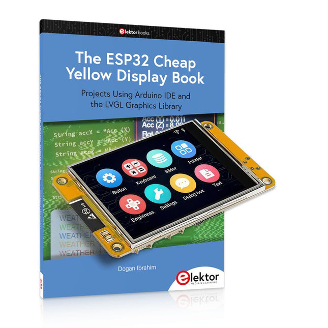
Over 40 Fully Tested ESP32 Projects Using Arduino IDE and the LVGL Graphics Library
This bundle includes the ESP32 Cheap Yellow Display (CYD) – a compact development board combining a standard ESP32 microcontroller with a 320x240 pixel TFT color display. The board also features multiple connectors for GPIO, serial communication (TX/RX), power, and ground. The built-in display is a major advantage, allowing users to create complex, graphics-based projects without the need for external LCDs or displays.
The accompanying book introduces the CYD board's hardware and on-board connectors in detail. It provides a range of beginner to intermediate-level projects developed using the popular Arduino IDE 2.0. Both basic graphics functions and the powerful LVGL graphics library are covered, with practical projects illustrating each approach.
All included projects have been fully tested and are ready to use. The book provides block diagrams, circuit schematics, complete code listings, and step-by-step explanations. With the LVGL library, readers can create modern, full-color graphical interfaces using widgets such as buttons, labels, sliders, calendars, keyboards, charts, tables, menus, animations, and more.
ESP32 Cheap Yellow Display Board
This development board (also known as "Cheap Yellow Display") is powered by the ESP-WROOM-32, a dual-core MCU with integrated Wi-Fi and Bluetooth capabilities. It operates at a main frequency of up to 240 MHz, with 520 KB SRAM, 448 KBROM, and a 4 MB Flash memory. The board features a 2.8-inch display with a resolution of 240x320 and resistive touch.
Furthermore, the board includes a backlight control circuit, touch control circuit, speaker drive circuit, photosensitive circuit, and RGB-LED control circuit. It also provides a TF card slot, serial interface, DHT11 temperature and humidity sensor interface, and additional IO ports.
The module supports development in Arduino IDE, ESP-IDE, MicroPython, and Mixly.
Applications
Image transmission for Smart Home device
Wireless monitoring
Smart agriculture
QR wireless recognition
Wireless positioning system signal
And other IoT applications
Specifications
Microcontroller
ESP-WROOM-32 (Dual-core MCU with integrated Wi-Fi and Bluetooth)
Frequency
Up to 240 MHz (computing power is up to 600 DMIPS)
SRAM
520 KB
ROM
448 KB
Flash
4 MB
Operating voltage
5 V
Power consumption
approx. 115 mA
Display
2.8-inch color TFT screen (240 x 320)
Touch
Resistive Touch
Driver chip
ILI9341
Dimensions
50 x 86 mm
Weight
50 g
Downloads
GitHub
Contents of the Bundle
The ESP32 Cheap Yellow Display Book (normal price: €35)
ESP32 Cheap Yellow Display Board (normal price: €25)
1x ESP32 Dev Board with 2.8" Display and acrylic Shell
1x Touch pen
1x Connector cable
1x USB cable
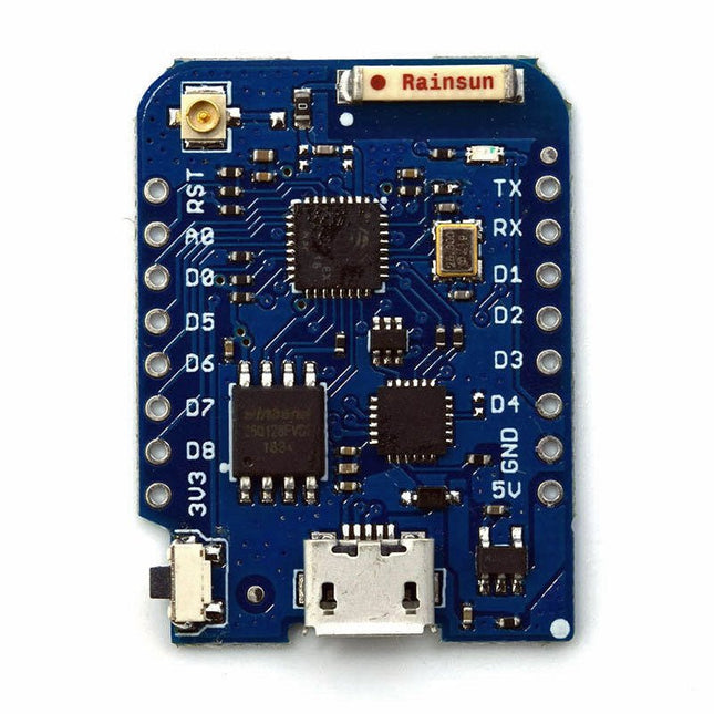
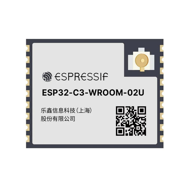
ESP32-C3-WROOM-02U is a general-purpose Wi-Fi and Bluetooth LE module. The rich set of peripherals and high performance make the module an ideal choice for smart homes, industrial automation, health care, consumer electronics, etc.
ESP32-C3-WROOM-02U features an external SPI flash and comes with a connector for an external antenna.
ESP32-C3-WROOM-02U has an operating ambient temperature option of –40∼85°C, embedded with the ESP32-C3 chip. ESP32-C3 has a 32-bit RISC-V single-core processor. It integrates a rich set of peripherals, ranging from UART, I²C, I²S, remote control peripheral, LED PWM controller, general DMA controller, TWAI controller, USB Serial/JTAG controller, temperature sensor, ADC, etc. It also includes SPI, Dual SPI and Quad SPI interfaces.
Features
Flash: 4 MB (Quad SPI)
Dimensions: 18.0 x 20.0 x 3.2 mm
Downloads
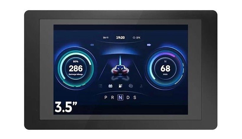
Datasheet
Introducing the Elecrow ESP32 Terminal, a revolutionary handheld device engineered to elevate your projects to new heights. Boasting a 3.5″ 480 × 320 TFT capacitive...