Search results for "elektor OR arduino OR electronics OR bundle"
-

Elektor Labs Elektor Arduino MultiCalculator
The Elektor MultiCalculator Kit is an Arduino-based multifunction calculator that goes beyond basic calculations. It offers 22 functions including light and temperature measurement, differential temperature analysis, and NEC IR remote control decoding. The Elektor MultiCalculator is a handy tool for use in your projects or for educational purposes. The kit features a Pro Mini module as the computing unit. The PCB is easy to assemble using through-hole components. The enclosure consists of 11 acrylic panels and mounting materials for easy assembly. Additionally, the device is equipped with a 16x2 alphanumeric LCD, 20 buttons, and temperature sensors. The Elektor MultiCalculator is programmable with the Arduino IDE through a 6-way PCB header. The available software is bilingual (English and Dutch). The calculator can be programmed with a programming adapter, and it is powered through USB-C. Modes of Operation Calculator 4-Ring Resistor Code 5-Ring Resistor Code Decimal to Hexadecimal and Character (ASCII) conversion Hexadecimal to Decimal and Character (ASCII) conversion Decimal to Binary and Character (ASCII) conversion Binary to Decimal and Hexadecimal conversion Hz, nF, capacitive reactance (XC) calculation Hz, µH, inductive reactance (XL) calculation Resistance calculation of two resistors connected in parallel Resistance calculation of two resistors connected in series Calculation of unknown parallel resistor Temperature measurement Differential temperature measurement T1&T2 and Delta (δ) Light measurement Stopwatch with lap time function Item counter NEC IR remote control decoding AWG conversion (American Wire Gauge) Rolling Dice Personalize startup message Temperature calibration Specifications Menu languages: English, Dutch Dimensions: 92 x 138 x 40 mm Build time: approx. 5 hours Included PCB and though-hole components Precut acrylic sheets with all mechanical parts Pro Mini microcontroller module (ATmega328/5 V/16 MHz) Programming adapter Waterproof temperature sensors USB-C cable Downloads Software
€ 49,95€ 39,95
Members identical
-
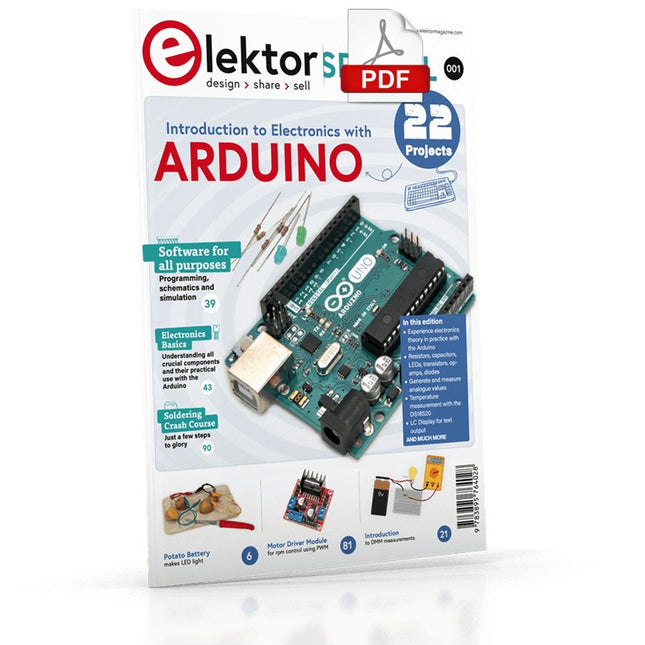
Elektor Digital Elektor Special: Introduction to Electronics with Arduino (PDF)
Although the Arduino isn’t a novelty any longer, there are still many beginners who want to try programming and development with a microcontroller, and to them, it is all new. All beginnings can be difficult, though they should be light and enjoyable. You do not need much or expensive equipment for the examples. The circuits are built on a small breadboard, and, if necessary, connected to an Arduino Uno, which you can program on a Windows PC. You will find clear examples of how to build all circuits, ensuring easy and error-free reproduction. Projects Discussed Current & Voltage – How it all began Arduino Hardware Arduino Programming The Electrical Circuit Measuring with the Multimeter Circuit Diagrams and Breadboards Creating Circuit Diagrams Breadboard Views with Fritzing Online Circuit Simulation Indispensable: Resistors (Part 1) Hands-on with Resistors (Part 2) Variable Resistors Diodes: One-way Street for Current The Transistor Switch Electromagnetism Relays and Motors op-amps: Operational Amplifiers Capacitors The NE555 Timer PWM and Analogue Values with Arduino 7-Segment Temperature Display Introduction to Soldering and LCDs
€ 11,95
Members € 10,76
-

Elektor Labs Elektor Arduino Nano MCCAB Training Board
The Elektor Arduino Nano MCCAB Training Board contains all the components (incl. Arduino Nano) required for the exercises in the "Microcontrollers Hands-on Course for Arduino Starters", such as light-emitting diodes, switches, pushbuttons, acoustic signal transmitters, etc. External sensors, motors or assemblies can also be queried or controlled with this microcontroller training system. Specifications (Arduino Nano MCCAB Training Board) Power Supply Via the USB connection of the connected PC or an external power supply unit (not included) Operating Voltage +5 Vcc Input Voltage All inputs 0 V to +5 V VX1 and VX2 +8 V to +12 V (only when using an external power supply) Hardware periphery LCD 2x16 characters Potentiometer P1 & P2 JP3: selection of operating voltage of P1 & P2 Distributor SV4: Distributor for the operating voltagesSV5, SV6: Distributor for the inputs/outputs of the microcontroller Switches and buttons RESET button on the Arduino Nano module 6x pushbutton switches K1 ... K6 6x slide switches S1 ... S6 JP2: Connection of the switches with the inputs of the microcontroller Buzzer Piezo buzzer Buzzer1 with jumper on JP6 Indicator lights 11 x LED: Status indicator for the inputs/outputs LED L on the Arduino Nano module, connected to GPIO D13 JP6: Connection of LEDs LD10 ... LD20 with GPIOs D2 ... D12 Serial interfacesSPI & I²C JP4: Selection of the signal at pin X of the SPI connector SV12 SV9 to SV12: SPI interface (3.3 V/5 V) or I²C interface Switching output for external devices SV1, SV7: Switching output (maximum +24 V/160 mA, externally supplied) SV2: 2x13 pins for connection of external modules 3x3 LED matrix(9 red LEDs) SV3: Columns of the 3x3 LED matrix (outputs D6 ... D8) JP1: Connection of the rows with the GPIOs D3 ... D5 Software Library MCCABLib Control of hardware components (switches, buttons, LEDs, 3x3 LED matrix, buzzer) on the MCCAB Training Board Operating Temperature Up to +40 °C Dimensions 100 x 100 x 20 mm Specifications (Arduino Nano) Microcontroller ATmega328P Architecture AVR Operating Voltage 5 V Flash Memory 32 KB, of which 2 KB used by bootloader SRAM 2 KB Clock Speed 16 MHz Analog IN Pins 8 EEPROM 1 KB DC Current per I/O Pins 40 mA on one I/O pin, total maximum 200 mA on all pins together Input Voltage 7-12 V Digital I/O Pins 22 (6 of which are PWM) PWM Output 6 Power Consumption 19 mA Dimensions 18 x 45 mm Weight 7 g Included 1x Elektor Arduino Nano Training Board MCCAB 1x Arduino Nano
€ 79,95
Members € 71,96
-
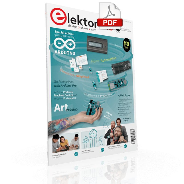
Elektor Digital Elektor Arduino Guest Edition 2022 (PDF) EN
Elektor GREEN and GOLD members can download their digital edition here. Not a member yet? Click here. Arduino Portenta Machine Control and Arduino Portenta H7A CAN-to-MQTT Gateway Demo Project Unboxing the Elektor LCR Meter with David Cuartielles MicroPython Enters the World of Arduino Connected Projects, SimplifiedDive Into the Arduino Cloud Introduction to TinyMLBig Is Not Always Better Arduino K-Way Writing Arduino Sketches Just Got Better Get to Know Arduino Getting Started with the Portenta X8Manage Software Securely with Containers Build, Deploy, and Maintain Scalable, Secure ApplicationsWith Arduino Portenta X8 Featuring NXP’s i.MX 8M Mini Applications Processor and EdgeLock SE050 Secure Element How I Automated My HomeArduino CEO Fabio Violante Shares Solutions Altair 8800 SimulatorHardware Simulation of a Vintage Computer MS-DOS on the Portenta H7Run Old-School Software on Contemporary Hardware Grow It YourselfA Digitally Controlled, Single-Box Solution for Indoor Farming Save the Planet With Home Automation?MQTT on the Arduino Nano RP2040 Connect Go Professional with Arduino Pro Smart Ovens Take a Leap Into the Future Tagvance Builds Safer Construction Sites with Arduino Santagostino Breathes Easywith Remote Monitoring that Leverages AI for Predictive Maintenance Security Flies High with RIoT Secure’s MKR-Based Solution Open-Source Brings a New Generation of Water Management to the World SensoDetect Deforestation with Sound Analysis The Mozzi Arduino Library for Sound SynthesisInsights from Tim Barrass The New Portenta X8 (with Linux!) and Max Carrier Redefine What’s Possible How Using Arduino Helps Students Build Future Skills Must-Haves for Your Electronics Workspace The Importance of Robotics in Education Dependable IoT Based Upon LoRa Unboxing the Portenta Machine Control 8-Bit Gaming with Arduboy Reducing Water Usage at Horseback Riding TracksAn IoT to Constantly Monitor Soil Humidity and Temperature Levels The Panettone ProjectA sourdough starter management and maintenance system Supporting Arduino Resellers Space Invaders with Arduino Art with ArduinoInspiring Insights from Artists and Designers Arduino Product Catalogue The Future of Arduino
€ 7,50
-
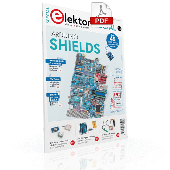
Elektor Digital Elektor Special: Arduino Shields (PDF) EN
Make your project dreams come true: an odometer for the hamster wheel, a fully automatic control of your ant farm with web interface, or the Sandwich-O-Mat – a machine that toasts and grills sandwiches of your choice. With the Arduino and the DIY or Maker movement, not only did entry into microcontroller programming become child's play, but a second development also took place: Resourceful developers brought small boards – so-called shields or modules – to the market, which greatly simplified the use of additional hardware. The small modules contain all the important electronic parts to be connected to the microcontroller with a few plug-in cables, eliminating the need for a fiddly and time-consuming assembly on the plug-in board. In addition, it is also possible to handle tiny components that do not have any connecting legs (so-called SMDs). Projects Discussed Arduino seeks connection BMP and introduction to libraries, I²C Learn I/O basics with the multi-purpose shield I²C LCD adapter and DOT matrix displays LCD keypad shield Level converter W5100: Internet connection I/O expansion shield Relays and solid-state relays The multi-function shield: A universal control unit Connecting an SD card reader via SPI Keys and 7-segment displays 16-bit ADC MCP4725 DAC 16-way PWM servo driver MP3 player GPS data logger using an SD card Touch sensor Joystick SHT31: Temperature and humidity VEML6070 UV-A sensor VL53L0X time-of-flight Ultrasonic distance meter MAX7219-based LED DOT matrix display DS3231 RTC Port expander MCP23017 433 MHz radio MPU-650 gyroscope ADXL345 accelerometer WS2812 RGB LEDs Power supply MQ-xx gas sensors CO2 gas sensor ACS712 current sensor INA219 current sensor L298 motor driver MFRC522 RFID 28BYJ-48 stepper motor TMC2209 silent step stick X9C10x digital potentiometer ST7735 in a color TFT display e-Paper display Bluetooth Geiger counter SIM800L GSM module I²C multiplexer Controller Area Network
€ 11,95
Members € 10,76
-

Elektor Bundles Arduino Uno R4 WiFi (Bundle)
Book: Mastering the Arduino Uno R4 Based on the low-cost 8-bit ATmega328P processor, the Arduino Uno R3 board is likely to score as the most popular Arduino family member, and this workhorse has been with us for many years. Eleven years later, the long-overdue successor, the Arduino Uno R4, was released. It is built around a 48 MHz, 32-bit Arm Cortex-M4 microcontroller and provides significantly expanded SRAM and Flash memory. Additionally, a higher-precision ADC and a new DAC are added to the design. The Uno R4 board also supports the CAN Bus with an interface. Two versions of the board are available: Uno R4 Minima, and Uno R4 WiFi. This book is about using these new boards to develop many different and interesting projects with just a handful of parts and external modules. All projects described in the book have been fully tested on the Uno R4 Minima or the Uno R4 WiFi board, as appropriate. The project topics include the reading, control, and driving of many components and modules in the kit as well as on the relevant Uno R4 board, including LEDs 7-segment displays (using timer interrupts) LCDs Sensors RFID Reader 4x4 Keypad Real-time clock (RTC) Joystick 8×8 LED matrix Motors DAC (Digital-to-analog converter) LED matrix WiFi connectivity Serial UART CAN bus Infrared controller and receiver Simulators … all in creative and educational ways with the project operation and associated software explained in great detail. Arduino Uno R4 WiFi The Arduino Uno R4 is powered by the Renesas RA4M1 32-bit ARM Cortex-M4 processor, providing a significant boost in processing power, memory, and functionality. The WiFi version comes with an ESP32-S3 WiFi module in addition to the RA4M1, expanding creative opportunities for makers and engineers. The Arduino Uno R4 runs at 48 MHz, which provides a 3x increase over the popular Uno R3. Additionally, SRAM has been upgraded from 2 kB to 32 kB, and flash memory from 32 kB to 256 kB to support more complex projects. Responding to community feedback, the USB port is now USB-C, and the maximum power supply voltage has been raised to 24 V with an enhanced thermal design. The board includes a CAN bus and an SPI port, enabling users to reduce wiring and perform parallel tasks by connecting multiple shields. A 12-bit analog DAC is also provided on the board. Specifications Microcontroller Renesas RA4M1 (ARM Cortex-M4) USB USB-C Programming Port Pins Digital I/O Pins 14 Pins Analog input pins 6 DAC 1 RTC 1 PWM pins 6 Communication UART 1x I²C 1x SPI 1x Qwiic I²C connector 1x CAN 1x CAN Bus Power Circuit operating voltage 5 V Input voltage (VIN) 6-24 V DC Current per I/O Pin 8 mA Clock speed Main core 48 MHz Memory RA4M1 256 kB Flash, 32 kB RAM LED Matrix 12 x 8 (96 red LEDs) Dimensions 68.9 x 53.4 mm Downloads Datasheet Schematics This bundle contains: Book: Mastering the Arduino Uno R4 (normal price: €40) Arduino Uno R4 WiFi (normal price: €30)
€ 69,95€ 59,95
Members identical
-
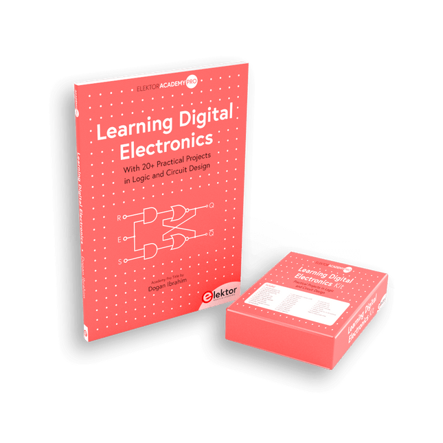
Elektor Bundles Learning Digital Electronics (Bundle)
Master digital electronics – the hands-on way! This bundle includes the book Learning Digital Electronics, featuring 20+ practical projects in Logic and Circuit design, as well as a 100-piece kit – so you can start building logic circuits, counters, displays, and more right away. Learning Digital Electronics (Book) This book is a practical guide to digital electronics, covering the essential components of modern digital systems: number systems, logic gates, Boolean algebra, combinational and sequential logic, and more. Through more than 20 structured projects, you’ll design and build digital systems using real-world components such as logic gates, multiplexers, decoders, flip-flops, counters, and shift registers. The projects range from basic LED logic circuits to digital locks, display systems, traffic light controllers, and timing-based designs. Selected projects introduce the use of tools such as CircuitVerse for circuit simulation, while several designs make use of 74HC-series logic devices, commonly used in digital hardware prototyping. Inside, you’ll find: Clear coverage of number systems and binary arithmetic Logic gate fundamentals and universal gate implementations Step-by-step projects using flip-flops, counters, and registers Real-world design with 74HC-series logic chips Techniques for designing combinational and sequential systems This book takes a design-first, application-driven approach to digital electronics—built around working circuits, tested logic, and hands-on experimentation. Learning Digital Electronics (Kit) This kit has been specially developed to complement the book "Learning Digital Electronics". Since all necessary components are included, you can complete every practical project in the book directly. Kit contents 2x 74HC08 AND gate chip 2x 74HC00 NAND gate chip 1x 74HC86 XOR gate chip 1x 555 timer chip 1x 74HC161 counter chip 1x 74HC164 shift register 1x CD4511 7-segment decoder 1x CD4027 JK flip-flop 1x BC337 NPN transistor 1x KPS-5161 7-segment common-cathode display 1x Light dependent resistor (LDR) 4x 10 KΩ resistors 8x 1 KΩ resistor 2x 47 KΩ resistors 1x 100 KΩ resistor 4x 2.7 KΩ resistors 1x 5.6 KΩ resistor 1x 150 KΩ resistor 1x 10 μF capacitor 2x 0.01 μF capacitor 2x 100 nF capacitor 8x Small red LED 1x Small green LED 1x Small orange LED 4x Pushbutton switches 1x Active buzzer 1x Battery holder for 3x AA batteries (batteries not included) 1x Breadboard 40x Male-to-male jumper wires (length: 200 mm)
€ 69,95€ 59,95
Members identical
-
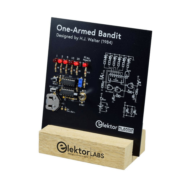
Elektor Labs Elektor One-armed Bandit
Pull Down Lever For Highest Score! This Elektor Circuit Classic from 1984 shows a playful application of CMOS 400x series logic ICs in combination with LEDs, a highly popular combination at the time. The project imitates a spinning-digit type slot machine. The Game To play the game, first agree on the number of rounds. Player 1 actuates the switch lever as long as desired and releases it. The LEDs then show the score which is the sum of the 50-20-10-5 digits lit up. If the Play Again! LED lights, Player 1 has another, “free” round. If not, it’s Player 2’s turn. The players keep tab of their scores, and the highest score wins. Features LEDs Indicate Score Multi-Player and Play Again! Elektor Heritage Circuit Symbols Tried & Tested by Elektor Labs Educational & Geeky Project Through-Hole Parts Only Included Printed Circuit Board All Components Wooden Stand Bill of Materials Resistors (5%, 250 mW) R1,R2,R3,R4 = 100kΩ R5,R6,R7,R8,R9,R10 = 1kΩ Capacitors C1 = 4.7nF, 10%, 50V, 5mm C2 = 4.7μF, 10%, 63V, axial C3,C4 = 100nF, 10 %, 50V, ceramic X7R, 5mm Semiconductors LED1-LED6 = red, 5mm (T1 3/4) IC1 = 74HC4024 IC2 = 74HC132 Miscellaneous S1 = switch, toggle, 21mm lever, SPDT, momentary S2 = switch, tactile, 24V, 50mA, 6x6mm S3 = switch, slide, SPDT IC1,IC2 = IC socket, DIP14 BT1 = PCB-mount CR2032 battery retainer clip Desktop Stand PCB 230098-1 Not included: BT1 = CR2032 coin cell battery
€ 39,95€ 15,98
Members identical
-
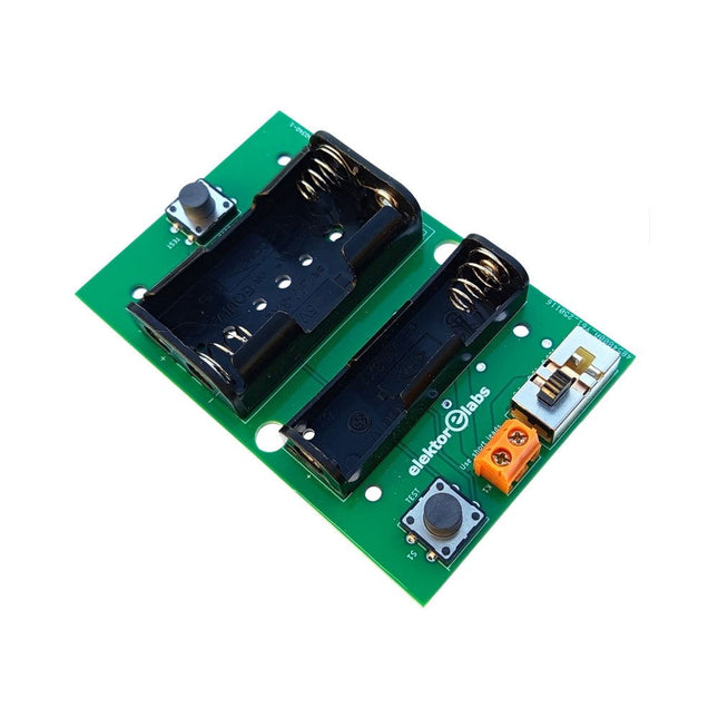
Elektor Labs Elektor Milliohmmeter Adapter
The Elektor Milliohmmeter Adapter uses the precision of a multimeter to measure very low resistance values. It is an adapter that converts a resistance into a voltage that can be measured with a standard multimeter. The Elektor Milliohmmeter Adapter can measure resistances below 1 mΩ using a 4-wire (Kelvin) method. It is useful for locating short circuits on printed circuit boards (PCB). The adapter features three measurement ranges – 1 mΩ, 10 mΩ, and 100 mΩ – selectable via a slide switch. It also includes onboard calibration resistors. The Elektor Milliohmmeter Adapter is powered by three 1.5 V AA batteries (not included). Specifications Measurement ranges 1 mΩ, 10 mΩ, 100 mΩ, 0.1% Power supply 3x 1.5 V AA batteries (not included) Dimensions 103 x 66 x 18 mm (compatible with Hammond 1593N-type enclosure, not included) Special feature On-board calibration resistors Downloads Documentation
€ 34,95
Members € 31,46
-
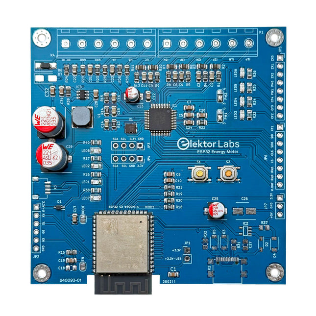
Elektor Labs Elektor ESP32 Energy Meter
The Elektor ESP32 Energy Meter is a device designed for real-time energy monitoring and smart home integration. Powered by the ESP32-S3 microcontroller, it offers robust performance with modular and scalable features. The device uses a 220 V-to-12 V step-down transformer for voltage sampling, ensuring galvanic isolation and safety. Its compact PCB layout includes screw-type terminal blocks for secure connections, a Qwiic connector for additional sensors, and a programming header for direct ESP32-S3 configuration. The energy meter is compatible with single-phase and three-phase systems, making it adaptable for various applications. The energy meter is simple to set up and integrates with Home Assistant, offering real-time monitoring, historical analytics, and automation capabilities. It provides accurate measurements of voltage, current, and power, making it a valuable tool for energy management in homes and businesses. Features Comprehensive Energy Monitoring: Get detailed insights into your energy usage for smarter management and cost savings. Customizable Software: Tailor functionality to your needs by programming and integrating custom sensors. Smart Home Ready: Compatible with ESPHome, Home Assistant, and MQTT for full Smart Home integration. Safe & Flexible Design: Operates with a 220 V-to-12 V step-down transformer and features a pre-assembled SMD board. Quick Start: Includes one Current Transformer (CT) sensor and access to free setup resources. Specifications Microcontroller ESP32-S3-WROOM-1-N8R2 Energy Metering IC ATM90E32AS Status Indicators 4x LEDs for power consumption indication2x Programmable LEDs for custom status notifications User Input 2x Push buttons for user control Display Output I²C OLED display for real-time power consumption visualization Input Voltage 110/220 V AC (via step-down transformer) Input Power 12 V (via step-down transformer or DC input) Clamp Current Sensor YHDC SCT013-000 (100 A/50 mA) included Smart Home Integration ESPHome, Home Assistant, and MQTT for seamless connectivity Connectivity Header for programming, Qwiic for sensor expansion Applications Supports single-phase and three-phase energy monitoring systems Dimensions 79.5 x 79.5 mm Included 1x Partly assembled board (SMDs are pre-mounted) 2x Screw terminal block connectors (not mounted) 1x YHDC SCT013-000 current transformer Required Power transformer not included Downloads Datasheet (ESP32-S3-WROOM-1) Datasheet (ATM90E32AS) Datasheet (SCT013-000) Frequently Asked Questions (FAQ) From Prototype to Finished Product What started as an innovative project to create a reliable and user-friendly energy meter using the ESP32-S3 microcontroller has evolved into a robust product. Initially developed as an open-source project, the ESP32 Energy Meter aimed to provide precise energy monitoring, smart home integration and more. Through meticulous hardware and firmware development, the energy meter now stands as a compact, versatile solution for energy management.
€ 79,95€ 64,95
Members identical


-

, by Lobna Belarbi Must-Have Boards, Kits & Tools to Start Your Arduino Journey with Elektor
Whether you're a newcomer eager to explore the world of microcontrollers or an experienced maker seeking to expand your toolkit, Elektor offers a curated selection...
-

, by Lobna Belarbi Kickstart Your Electronics Journey with Elektor’s Learning Collection
Whether you're new to electronics or aiming to level up your embedded skills, Elektor’s Learning Collection delivers expert-curated kits, courses, and hands-on bundles. The first...

