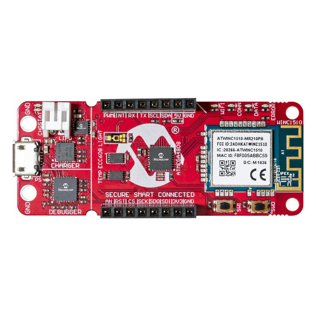
The AVR-IoT WA development board combines a powerful ATmega4808 AVR MCU, an ATECC608A CryptoAuthentication secure element IC and the fully certified ATWINC1510 Wi-Fi network controller – which provides the most simple and effective way to connect your embedded application to Amazon Web Services (AWS). The board also includes an on-board debugger, and requires no external hardware to program and debug the MCU.
Out of the box, the MCU comes preloaded with a firmware image that enables you to quickly connect and send data to the AWS platform using the on-board temperature and light sensors. Once you are ready to build your own custom design, you can easily generate code using the free software libraries in Atmel START or MPLAB Code Configurator (MCC).
The AVR-IoT WA board is supported by two award-winning Integrated Development Environments (IDEs) – Atmel Studio and Microchip MPLAB X IDE – giving you the freedom to innovate with your environment of choice.
Features
ATmega4808 microcontroller
Four user LED’s
Two mechanical buttons
mikroBUS header footprint
TEMT6000 Light sensor
MCP9808 Temperature sensor
ATECC608A CryptoAuthentication™ device
WINC1510 WiFi Module
On-board Debugger
Auto-ID for board identification in Atmel Studio and Microchip MPLAB X
One green board power and status LED
Programming and debugging
Virtual COM port (CDC)
Two DGI GPIO lines
USB and battery powered
Integrated Li-Ion/LiPo battery charger
Ready-to-use devices and self-built Arduino nodes in the 'The Things Network'
LoRaWAN has developed excellently as a communication solution in the IoT. The Things Network (TTN) has contributed to this. The Things Network was upgraded to The Things Stack Community Edition (TTS (CE)). The TTN V2 clusters were closed towards the end of 2021.
This book shows you the necessary steps to operate LoRaWAN nodes using TTS (CE) and maybe extend the network of gateways with an own gateway. Meanwhile, there are even LoRaWAN gateways suitable for mobile use with which you can connect to the TTN server via your cell phone.
The author presents several commercial LoRaWAN nodes and new, low-cost and battery-powered hardware for building autonomous LoRaWAN nodes. Registering LoRaWAN nodes and gateways in the TTS (CE), providing the collected data via MQTT and visualization via Node-RED, Cayenne, Thingspeak, and Datacake enable complex IoT projects and completely new applications at very low cost.
This book will enable you to provide and visualize data collected with battery-powered sensors (LoRaWAN nodes) wirelessly on the Internet. You will learn the basics for smart city and IoT applications that enable, for example, the measurement of air quality, water levels, snow depths, the determination of free parking spaces (smart parking), and the intelligent control of street lighting (smart lighting), among others.
There are many so-called 'Arduino compatible' platforms on the market. The ESP8266 – in the form of the WeMos D1 Mini Pro – is one that really stands out. This device includes WiFi Internet access and the option of a flash file system using up to 16 MB of external flash memory. Furthermore, there are ample in/output pins (though only one analogue input), PWM, I²C, and one-wire. Needless to say, you are easily able to construct many small IoT devices!
This book contains the following builds:
A colourful smart home accessory
refrigerator controller
230 V power monitor
door lock monitor
and some further spin-off devices.
All builds are documented together with relevant background information for further study. For your convenience, there is a small PCB for most of the designs; you can also use a perf board. You don’t need to be an expert but the minimum recommended essentials include basic experience with a PC, software, and hardware, including the ability to surf the Internet and assemble PCBs.
And of course: A handle was kept on development costs. All custom software for the IoT devices and PCB layouts are available for free download from at Elektor.com.
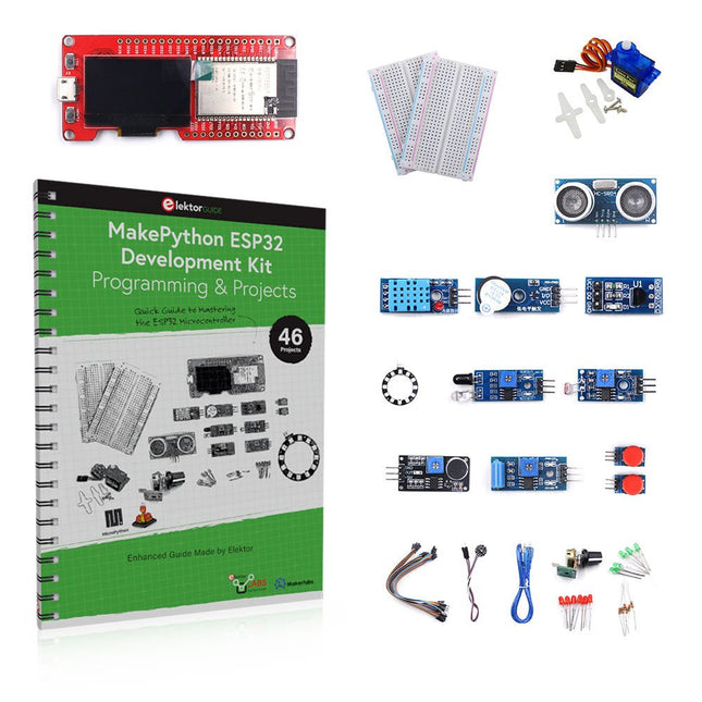
Learn how to use the ESP32 Microcontroller and MicroPython programming in your future projects!
The project book, written by well-known Elektor author Dogan Ibrahim, holds many software- and hardware-based projects especially developed for the MakePython ESP32 Development Kit. The kit comes with several LEDs, sensors, and actuators. The kit will help you acquire the basic knowledge to create IoT projects.
The book’s fully evaluated projects feature all the supplied components. Each project includes a block diagram, a circuit diagram, a full program listing, and a complete program description.
Included in the kit
1x MakePython ESP32 development board with LCD
1x Ultrasonic ranging module
1x Temperature and humidity sensor
1x Buzzer module
1x DS18B20 module
1x Infrared module
1x Potentiometer
1x WS2812 module
1x Sound sensor
1x Vibration sensor
1x Photosensitive resistance module
1x Pulse sensor
1x Servo motor
1x USB cable
2x Button
2x Breadboard
45x Jumper wire
10x Resistor 330R
10x LED (Red)
10x LED (Green)
1x Project book (206 pages)
46 Projects in the Book
LED Projects
Blinking LED
Flashing SOS
Blinking LED – using a timer
Alternately flashing LEDs
Button control
Changing the LED flashing rate using pushbutton interrupts
Chasing-LEDs
Binary-counting LEDs
Christmas lights (random-flashing 8 LEDs)
Electronic dice
Lucky day of the week
Pulsewidth Modulation (PWM) Projects
Generate a 1000-Hz PWM waveform with 50% duty cycle
LED brightness control
Measuring the frequency and duty cycle of a PWM waveform
Melody maker
Simple electronic organ
Servo motor control
Servo motor DS18B20 thermometer
Analog To Digital Converter (ADC) Projects
Voltmeter
Plotting the analog input voltage
ESP32 internal temperature sensor
Ohmmeter
Photosensitive resistance module
Digital To Analog Converter (DAC) Projects
Generating fixed voltages
Generating a sawtooth-wave signal
Generating a triangular-wave signal
Arbitrary periodic waveform
Generating a sinewave signal
Generating accurate sinewave signal using timer interrupts
Using The OLED Display
Seconds counter
Event counter
DS18B20 OLED based digital thermometer
ON-OFF temperature controller
Measuring the temperature and humidity
Ultrasonic distance measurement
Height of a person (stadiometer)
Heart rate (pulse) measurement
Other Sensors Supplied with the Kit
Theft alarm
Sound-activated light
Infrared obstacle avoidance with buzzer
WS2812 RGB LED ring
Timestamping temperature and humidity readings
Network Programming
Wi-Fi scanner
Remote control from the Internet browser (using a smartphone or PC) – Web Server
Storing temperature and humidity data in the Cloud
Low-Power Operation
Using a timer to wake up the processor
Affordable solutions with the ESP8266 and 3D printing
If you are looking for a small yet powerful IoT device, you are likely to come across the ESP8266 and compatible products on the market today. One of these, the Wemos/Lolin D1 Mini Pro board strikes a remarkable balance between cost and performance. A small and very affordable prototype board, the D1 Mini Pro stands out with its WiFi functionality and a 16-Mbytes flash memory for easy creation of a flash file system. In addition, there are sufficient input and output pins (only one analog input though) to support PWM, I²C, and One-Wire systems to mention but a few. The book describes the operation, modding, construction, and programming of home appliances including a colorful smart home accessory, a refrigerator/greenhouse controller, an AC powerline monitor, a door lock monitor, and an IKEA Trådfri controller.
As a benefit, all firmware developed for these DIY, "IoT-ized" devices can be updated over-the-air (OTA).
For most of the designs in the book, a small printed circuit board (PCB) and an enclosure are presented so readers can have a finished and attractive-looking product. Readers having – or with access to! – a 3D printer can "print" the suggested enclosures at home or in a shop.
Some of the constructions benefit from a Raspberry Pi configured as a gateway or cms server. This is also described in detail with all the necessary configuring.
You don’t need to be an expert but the prerequisites to successful replication of the projects include basic skills with PC software including the ability to surf the Internet. In terms of hardware, you should be comfortable with soldering and generally assembling the PCBs presented in the book.
All custom software written for the IoT devices, the PCB layouts, and 3D print files described in the book are available for free downloading.
Specifications
Bandwidth
100 MHz
Sample Rate
100 MS/s
Horizontal Scale (s/div)
5ns/div - 1000s/div, step by 1 - 2 - 5
Channel
4
Display
7" color LCD, 800 x 480 pixels
Input Coupling
DC, AC and GND
Vertical Resolution (A/D)
Vertical Resolution (A/D)
Vertical Sensitivity
5mV/div - 5V/div (at input)
Trigger Type
Edge, Video
Trigger Mode
Auto, Normal and Single
Waveform Math
+, -, x, ÷, invert, FFT
Fuse
2A, T class, 250 V
Dimension (W x H x D)
301 x 152 x 70 mm
Weight
1.1 kg
Included
1 x SDS1104
1 x Mains power cord
1 x CD Rom
1 x Quickstart Guide
1 x USB Cable
4 x Oscilloscope probe
1 x Probe Adjust
For more information, check out the user manual here.
Specifications
Bandwidth: 50 MHz
Analog Channels: 4
Real-time sample rate up to 1 GS/s
Memory depth up to 24 Mpts
Up to 30,000 wfms/s waveform capture rate
Up to 60,000 frames hardware real-time waveform recording and playback functions
Innovative 'UltraVision' technology
Various trigger and bus decoding functions
Low noise floor, vertical scale range: 1 mV/div to 10 V/div
Various interfaces: USB Host&Device, LAN (LXI), AUX
Compact size, light weight, easy to use
7 inch WVGA (800x480) TFT LCD, intensity graded color display
Included
1x Rigol DS1054Z Oscilloscope
1x Power cord
1x USB cable
4x PVP2150 Passive oscilloscope probe (150 MHz)
The OWON ADS900A series is a compact 12-bit digital oscilloscope offering up to 2 GSa/s, 100 Mpts memory, and 125/250 MHz bandwidth. With its 7" multi-touch display, FFT, protocol decoding, and integrated logic analyzer, it delivers precise signal analysis for lab, workshop, and field applications.
Specifications
ADS914A
ADS924A
Bandwidth (-3 dB)
125 MHz
250 MHz
Channels
4
Max. sample rate
2 GSa/s (single-channel) 1 GSa/s (dual-channel) 500 MSa/s (full-channel)
DC Gain Accuracy
3% (≤1 mV)
2% (≥2 mV)
Max memory depth
100M
Vertical resolution
12 bits
Relay time accuracy
±25 ppm (typical)
Input Impedance
1 MΩ±2%, parallel with20 pF±5 pF
Probe Attenuation Coefficient
1.00μX-1M.00X,step by 1-2-5, support custom
Trigger type
Edge, Video, Pulse, Slope, Runt, Windows, Timeout, Nth, Logic, RS232/UART, I²C, SPI CAN, LIN
Bus decoding
RS232/UART, I²C, SPI, CAN, LIN
Auto measurement
Period, Frequency, +Width, -Width, Rise Time, Fall Time, Scr Duty, +Duty,-Duty, Vavg, Vpp, VRMS, Overshoot, Vmax, Vmin, Vtop, CycRms, Vbase, Vamp, Preshoot, Std Dev, +Pulse Cnt, -Pulse Cnt, Rise Cnt, Fall Cnt, Area, Cyc Area, Delay(A↑-B↑), Delay(A↑-B↓), Delay(A↓-B↑), Delay(A↓-B↓), Phase(A↑-B↑)
Phase(A↑-B↓), Phase(A↓-B↑), Phase(A↓-B↓), FRR(A↑-B↑), FRF(A↑-B↓)
FFR(A↓-B↑), FFF(A↓-B↓), LRR(A↑-B↑), LRF(A↑-B↓), LFR(A↓-B↑), LFF(A↓-B↓)
Waveform Math
+, -, *, /, &&, ||, ^, !, Intg, Diff, Sqrt, Function operation (Lg / Ln / Exp / Abs / Sine / Cosine / Tan), FFT, FFT rms, User Defined, digital filter (low pass, high pass, band pass, band reject)
Frequency counter
6-digit frequency counter
Maximum frequency: maximum analog bandwidth of oscilloscope
Voltmeter
Support DC, AC+DCrms, ACrms, Resolution: 4 digits (ACV/DCV)
Logical Analyzer Specifications
Number of channels
16 input channels (D0-D15) (D0 to D7, D8 to D15)
Max. input voltage
±40V peak CAT I, transient overvoltage 800Vpk
Input Impedance
100kΩ, 8 pF
Vertical resolution
1 bit
Other
Communication Interface
HDMI, USB device, USB Host, Trig Out (P/F), LAN
Display
7 inch (1024x600), capacitive multi-touch screen
Power supply interface
USB-C
Dimensions
260 x 160 x 78 mm
Weight
1.5 kg
Included
1x OWON ADS924A Oscilloscope
1x Power Adapter
1x Power Cord
1x USB Cable
1x Probe
1x Quick Guide
Downloads
Manual
Quick Guide
PC Software
The OWON ADS900A series is a compact 12-bit digital oscilloscope offering up to 2 GSa/s, 100 Mpts memory, and 125/250 MHz bandwidth. With its 7" multi-touch display, FFT, protocol decoding, and integrated logic analyzer, it delivers precise signal analysis for lab, workshop, and field applications.
Specifications
ADS914A
ADS924A
Bandwidth (-3 dB)
125 MHz
250 MHz
Channels
4
Max. sample rate
2 GSa/s (single-channel) 1 GSa/s (dual-channel) 500 MSa/s (full-channel)
DC Gain Accuracy
3% (≤1 mV)
2% (≥2 mV)
Max memory depth
100M
Vertical resolution
12 bits
Relay time accuracy
±25 ppm (typical)
Input Impedance
1 MΩ±2%, parallel with20 pF±5 pF
Probe Attenuation Coefficient
1.00μX-1M.00X,step by 1-2-5, support custom
Trigger type
Edge, Video, Pulse, Slope, Runt, Windows, Timeout, Nth, Logic, RS232/UART, I²C, SPI CAN, LIN
Bus decoding
RS232/UART, I²C, SPI, CAN, LIN
Auto measurement
Period, Frequency, +Width, -Width, Rise Time, Fall Time, Scr Duty, +Duty,-Duty, Vavg, Vpp, VRMS, Overshoot, Vmax, Vmin, Vtop, CycRms, Vbase, Vamp, Preshoot, Std Dev, +Pulse Cnt, -Pulse Cnt, Rise Cnt, Fall Cnt, Area, Cyc Area, Delay(A↑-B↑), Delay(A↑-B↓), Delay(A↓-B↑), Delay(A↓-B↓), Phase(A↑-B↑)
Phase(A↑-B↓), Phase(A↓-B↑), Phase(A↓-B↓), FRR(A↑-B↑), FRF(A↑-B↓)
FFR(A↓-B↑), FFF(A↓-B↓), LRR(A↑-B↑), LRF(A↑-B↓), LFR(A↓-B↑), LFF(A↓-B↓)
Waveform Math
+, -, *, /, &&, ||, ^, !, Intg, Diff, Sqrt, Function operation (Lg / Ln / Exp / Abs / Sine / Cosine / Tan), FFT, FFT rms, User Defined, digital filter (low pass, high pass, band pass, band reject)
Frequency counter
6-digit frequency counter
Maximum frequency: maximum analog bandwidth of oscilloscope
Voltmeter
Support DC, AC+DCrms, ACrms, Resolution: 4 digits (ACV/DCV)
Logical Analyzer Specifications
Number of channels
16 input channels (D0-D15) (D0 to D7, D8 to D15)
Max. input voltage
±40V peak CAT I, transient overvoltage 800Vpk
Input Impedance
100kΩ, 8 pF
Vertical resolution
1 bit
Other
Communication Interface
HDMI, USB device, USB Host, Trig Out (P/F), LAN
Display
7 inch (1024x600), capacitive multi-touch screen
Power supply interface
USB-C
Dimensions
260 x 160 x 78 mm
Weight
1.5 kg
Included
1x OWON ADS914A Oscilloscope
1x Power Adapter
1x Power Cord
1x USB Cable
1x Probe
1x Quick Guide
Downloads
Manual
Quick Guide
PC Software
,
by Jean-François Simon
The RC-RICK-868-EV Wireless Modem: A Compelling Addition to Your Workbench
In this review, we're exploring the RC-RICK-868-EV, a specialized evaluation kit by Radiocontrolli designed for their RC-RICK-868 radio modem. This device stands out by employing...
,
by Saad Imtiaz
SparkFun Thing Plus Matter (MGM240P): A Versatile Matter-Based IoT Development Board (Review)
The SparkFun Thing Plus Matter (MGM240P) is a versatile and feature-rich development board designed for creating Matter-based IoT devices. Matter, formerly known as Project CHIP...
,
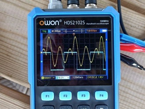
by Clemens Valens
Owon HDS2102S Handheld 2-Channel 100 MHz Oscilloscope, Multimeter & Signal Generator (Review)
The Owon HDS2102S is a versatile handheld device that combines a two-channel 100 MHz oscilloscope, a multimeter, and an arbitrary waveform generator all in one...