Search results for "dragino OR lora OR gps OR hat OR for OR"
-
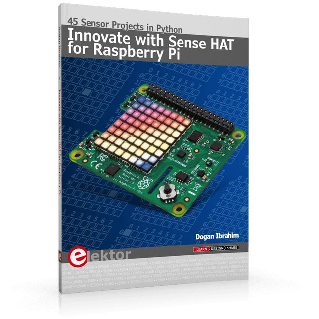
Elektor Publishing Innovate with Sense HAT for Raspberry Pi
Ready to explore the world around you? By attaching the Sense HAT to your Raspberry Pi, you can quickly and easily develop a variety of creative applications, useful experiments, and exciting games. The Sense HAT contains several helpful environmental sensors: temperature, humidity, pressure, accelerometer, magnetometer, and gyroscope. Additionally, an 8x8 LED matrix is provided with RGB LEDs, which can be used to display multi-color scrolling or fixed information, such as the sensor data. Use the small onboard joystick for games or applications that require user input. In Innovate with Sense HAT for Raspberry Pi, Dr. Dogan Ibrahim explains how to use the Sense HAT in Raspberry Pi Zero W-based projects. Using simple terms, he details how to incorporate the Sense HAT board in interesting visual and sensor-based projects. You can complete all the projects with other Raspberry Pi models without any modifications. Exploring with Sense HAT for Raspberry Pi includes projects featuring external hardware components in addition to the Sense HAT board. You will learn to connect the Sense HAT board to the Raspberry Pi using jumper wires so that some of the GPIO ports are free to be interfaced to external components, such as to buzzers, relays, LEDs, LCDs, motors, and other sensors. The book includes full program listings and detailed project descriptions. Complete circuit diagrams of the projects using external components are given where necessary. All the projects were developed using the latest version of the Python 3 programming language. You can easily download projects from the book’s web page. Let’s start exploring with Sense HAT.
€ 34,95
Members € 31,46
-
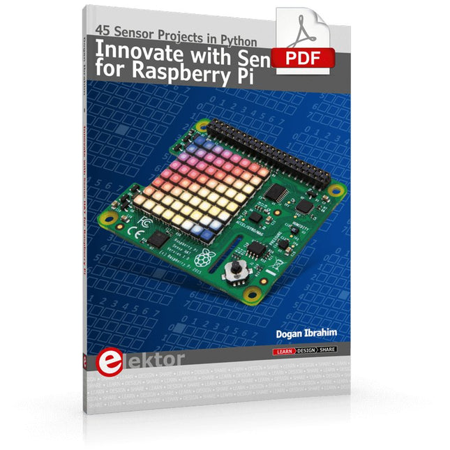
Elektor Digital Innovate with Sense HAT for Raspberry Pi (E-book)
Ready to explore the world around you? By attaching the Sense HAT to your Raspberry Pi, you can quickly and easily develop a variety of creative applications, useful experiments, and exciting games. The Sense HAT contains several helpful environmental sensors: temperature, humidity, pressure, accelerometer, magnetometer, and gyroscope. Additionally, an 8x8 LED matrix is provided with RGB LEDs, which can be used to display multi-color scrolling or fixed information, such as the sensor data. Use the small onboard joystick for games or applications that require user input. In Innovate with Sense HAT for Raspberry Pi, Dr. Dogan Ibrahim explains how to use the Sense HAT in Raspberry Pi Zero W-based projects. Using simple terms, he details how to incorporate the Sense HAT board in interesting visual and sensor-based projects. You can complete all the projects with other Raspberry Pi models without any modifications. Exploring with Sense HAT for Raspberry Pi includes projects featuring external hardware components in addition to the Sense HAT board. You will learn to connect the Sense HAT board to the Raspberry Pi using jumper wires so that some of the GPIO ports are free to be interfaced to external components, such as to buzzers, relays, LEDs, LCDs, motors, and other sensors. The book includes full program listings and detailed project descriptions. Complete circuit diagrams of the projects using external components are given where necessary. All the projects were developed using the latest version of the Python 3 programming language. You can easily download projects from the book’s web page. Let’s start exploring with Sense HAT.
€ 29,95
Members € 23,96
-
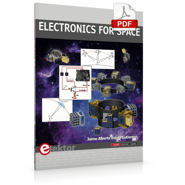
Elektor Digital Electronics for Space (E-book)
Space, the final frontier, will become more and more popular. The space industry is continually growing and new products and services will be required. Innovation is needed for the development of this industry. Today it is no longer possible to follow all the events in field of space. The space market is growing and activities are increasing, especially the market for small-satellites. This book wants to help close the gap and encourage electronic engineers to enter into the fascinating field of space electronics. One of the main difficulties is finding people with knowledge of space electronics design. Nowadays companies have to invest a lot of time and resources to instruct electronic engineers with no experience of space. Only a brief and basic introduction of this topic is typically achieved at university in space engineering lectures. Professionals with practical experience and the necessary theoretical knowledge are scarce. Companies from the space sector are searching for staff with knowledge of space electronics. This book will bring space closer aspiring to the space electronic hobbyists.
€ 24,95
Members € 19,96
-
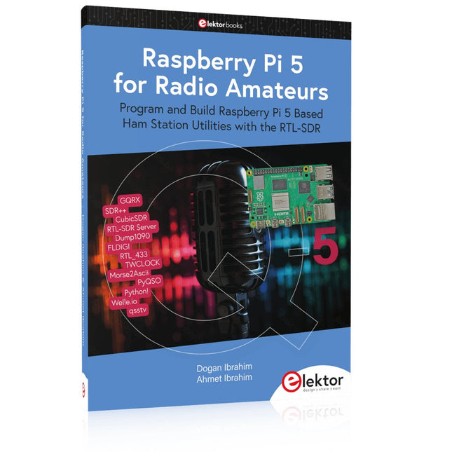
Elektor Publishing Raspberry Pi 5 for Radio Amateurs
Program and Build Raspberry Pi 5 Based Ham Station Utilities with the RTL-SDR The RTL-SDR devices (V3 and V4) have gained popularity among radio amateurs because of their very low cost and rich features. A basic system may consist of a USB based RTL-SDR device (dongle) with a suitable antenna, a Raspberry Pi 5 computer, a USB based external audio input-output adapter, and software installed on the Raspberry Pi 5 computer. With such a modest setup, it is possible to receive signals from around 24 MHz to over 1.7 GHz. This book is aimed at amateur radio enthusiasts and electronic engineering students, as well as at anyone interested in learning to use the Raspberry Pi 5 to build electronic projects. The book is suitable for both beginners through experienced readers. Some knowledge of the Python programming language is required to understand and eventually modify the projects given in the book. A block diagram, a circuit diagram, and a complete Python program listing is given for each project, alongside a comprehensive description. The following popular RTL-SDR programs are discussed in detail, aided by step-by-step installation guides for practical use on a Raspberry Pi 5: SimpleFM GQRX SDR++ CubicSDR RTL-SDR Server Dump1090 FLDIGI Quick RTL_433 aldo xcwcp GPredict TWCLOCK CQRLOG klog Morse2Ascii PyQSO Welle.io Ham Clock CHIRP xastir qsstv flrig XyGrib FreeDV Qtel (EchoLink) XDX (DX-Cluster) WSJT-X The application of the Python programming language on the latest Raspberry Pi 5 platform precludes the use of the programs in the book from working on older versions of Raspberry Pi computers.
€ 39,95
Members € 35,96
-
Elektor Publishing Coding Modbus TCP/IP for Arduino
Example projects with Node-RED, MQTT, WinCC SCADA, Blynk, and ThingSpeak This comprehensive guide unlocks the power of Modbus TCP/IP communication with Arduino. From the basics of the Modbus protocol right up to full implementation in Arduino projects, the book walks you through the complete process with lucid explanations and practical examples. Learn how to set up Modbus TCP/IP communication with Arduino for seamless data exchange between devices over a network. Explore different Modbus functions and master reading and writing registers to control your devices remotely. Create Modbus client and server applications to integrate into your Arduino projects, boosting their connectivity and automation level. With detailed code snippets and illustrations, this guide is perfect for beginners and experienced Arduino enthusiasts alike. Whether you‘re a hobbyist looking to expand your skills or a professional seeking to implement Modbus TCP/IP communication in your projects, this book provides all the knowledge you need to harness the full potential of Modbus with Arduino. Projects covered in the book: TCP/IP communication between two Arduino Uno boards Modbus TCP/IP communication within the Node-RED environment Combining Arduino, Node-RED, and Blynk IoT cloud Interfacing Modbus TCP/IP with WinCC SCADA to control sensors Using MQTT protocol with Ethernet/ESP8266 Connecting to ThingSpeak IoT cloud using Ethernet/ESP8266
€ 39,95
Members identical
-

Elektor Publishing FreeCAD for Electronics Applications
Practical Introduction to 3D Modeling from Enclosure to Front Panel Embedding a vintage component, creating a professional looking home for a circuit board, or even designing a complex apparatus complete with a chassis – these and many other challenges turn into a stimulating pleasure with FreeCAD. Once you have internalized the basic processes, there are virtually no limits to your imagination. Starting to use a new software is never straightforward – especially with a tool as versatile as FreeCAD. Manageable, but at the same time easily usable individual components provide the starting point in this book. Putting these components together later results in assemblies. In the FreeCAD universe, a workable trajectory is demonstrated. The described procedure is illustrative so the examples are easily applied to custom tasks. The devices were made by the author and illustrated with photos. Creating a 3D design is requiring some effort but the initial investment pays off soon. Besides the impressive spatial representation of the projects, the extracted drawings yield a solid base for documentation and production. Extended FreeCAD capabilities like the unfolding of sheet metal parts enormously add to efficiency and pushes models forward into practical assembly. Soon you will definitely not want to do without FreeCAD!
€ 44,95
Members € 40,46
-
Elektor Publishing Basic Electronics for Beginners
Analogue Electronics and Microcontrollers Projects Hobbyist electronics can be a fun way to learn new skills that can be helpful to your career. Those who understand the basics of electronics can design their own circuits and projects. However, before you run, you need to learn to walk. It all starts with analogue electronics. You should be familiar with the simple components and circuits and understand their basic behaviors and the issues you may encounter. The best way to do this is through real experiments. Theory alone is not enough. This book offers a large number of practical entry-level circuits, with which everyone can gain the basic experience. Through the widespread introduction of microcontrollers, a new chapter in electronics has begun. Microcontrollers are now performing more and more tasks that were originally solved using discrete components and conventional ICs. Starting out has become easier and easier thanks to platforms including Bascom, Arduino, micro:bit. The book introduces numerous manageable microcontroller applications. It’s now a case of less soldering and more programming.
€ 39,95€ 19,95
Members identical
-
Elektor Digital Hardware Projects for Raspberry Pi (E-book)
The Raspberry Pi is a $35 credit-card sized computer with many applications, such as in desktop computing, audio and video playback, and as a controller in many industrial, commercial and domestic applications. This book is about the Raspberry Pi computer and its use in control applications. The book explains in simple terms, with examples, how to configure the RPi, how to install and use the Linux operating system, how to write programs using the Python programming language and how to develop hardware based projects. The book starts with an introduction to the Raspberry Pi computer and covers the topics of purchasing all the necessary equipment and installing/using the Linux operating system in command mode. Use of the user-friendly graphical desktop operating environment is explained using example applications. The RPi network interface is explained in simple steps and demonstrates how the computer can be accessed remotely from a desktop or a laptop computer. The remaining parts of the book cover the Python programming language, hardware development tools, hardware interface details, and RPi based hardware projects. All the 23 projects given in the book have been tested and are working. The following headings are given for each project: Project title Project description Project block diagram Project circuit diagram Project program description using the Program Description Language (PDL) Complete program listing Description of the program The book is ideal for self-study, and is intended for electronic/electrical engineering students, practising engineers, research students, and hobbyists.
€ 34,95
Members € 27,96
-
Elektor Digital Raspberry Pi Pico for Radio Amateurs (E-book)
Program and build RPi Pico-based ham station utilities, tools, and instruments Although much classical HF and mobile equipment is still in use by large numbers of amateurs, the use of computers and digital techniques has now become very popular among amateur radio operators. Nowadays, anyone can purchase a €5 Raspberry Pi Pico microcontroller board and develop many amateur radio projects using the “Pico” and some external components. This book is aimed at amateur radio enthusiasts, Electronic Engineering students, and anyone interested in learning to use the Raspberry Pi Pico to shape their electronic projects. The book is suitable for beginners in electronics as well as for those with wide experience. Step-by-step installation of the MicroPython programming environment is described. Some knowledge of the Python programming language is helpful to be able to comprehend and modify the projects given in the book. The book introduces the Raspberry Pi Pico and gives examples of many general-purpose, software-only projects that familiarize the reader with the Python programming language. In addition to the software-only projects tailored to the amateur radio operator, Chapter 6 in particular presents over 36 hardware-based projects for “hams”, including: Station mains power on/off control Radio station clock GPS based station geographical coordinates Radio station temperature and humidity Various waveform generation methods using software and hardware (DDS) Frequency counter Voltmeter / ammeter / ohmmeter / capacitance meter RF meter and RF attenuators Morse code exercisers RadioStation Click board Raspberry Pi Pico based FM radio Using Bluetooth and Wi-Fi with Raspberry Pi Pico Radio station security with RFID Audio amplifier module with rotary encoder volume control Morse decoder Using the FS1000A TX-RX modules to communicate with Arduino
€ 32,95
Members € 26,36
-
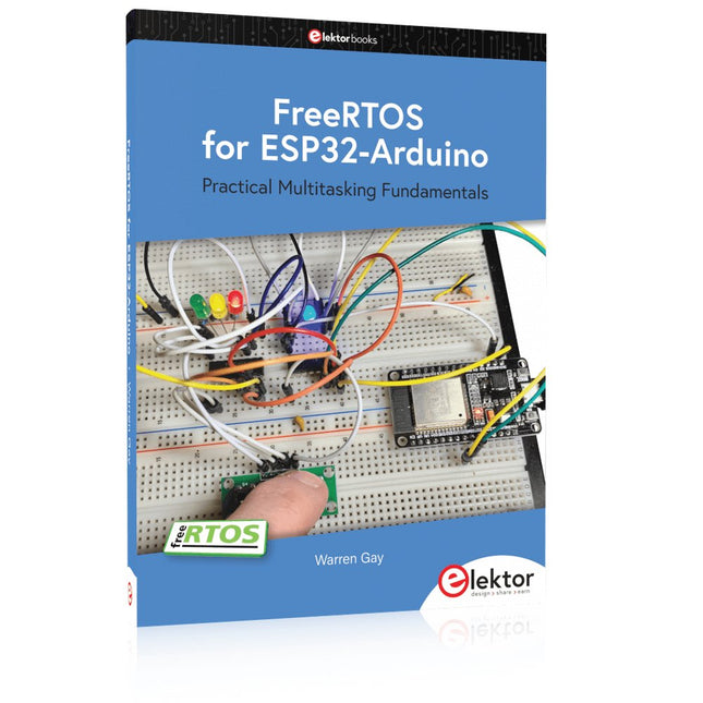
Elektor Publishing FreeRTOS for ESP32-Arduino
Practical Multitasking Fundamentals Programming embedded systems is difficult because of resource constraints and limited debugging facilities. Why develop your own Real-Time Operating System (RTOS) as well as your application when the proven FreeRTOS software is freely available? Why not start with a validated foundation? Every software developer knows that you must divide a difficult problem into smaller ones to conquer it. Using separate preemptive tasks and FreeRTOS communication mechanisms, a clean separation of functions is achieved within the entire application. This results in safe and maintainable designs. Practicing engineers and students alike can use this book and the ESP32 Arduino environment to wade into FreeRTOS concepts at a comfortable pace. The well-organized text enables you to master each concept before starting the next chapter. Practical breadboard experiments and schematics are included to bring the lessons home. Experience is the best teacher. Each chapter includes exercises to test your knowledge. The coverage of the FreeRTOS Application Programming Interface (API) is complete for the ESP32 Arduino environment. You can apply what you learn to other FreeRTOS environments, including Espressif’s ESP-IDF. The source code is available from GitHub. All of these resources put you in the driver’s seat when it is time to develop your next uber-cool ESP32 project. What you will learn: How preemptive scheduling works within FreeRTOS The Arduino startup “loopTask” Message queues FreeRTOS timers and the IDLE task The semaphore, mutex, and their differences The mailbox and its application Real-time task priorities and its effect Interrupt interaction and use with FreeRTOS Queue sets Notifying tasks with events Event groups Critical sections Task local storage The gatekeeper task
€ 44,95
Members € 40,46
-
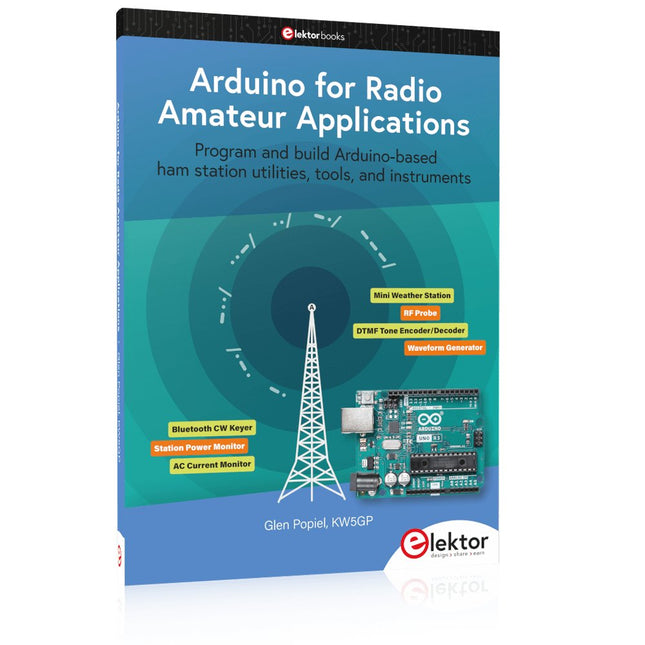
Elektor Publishing Arduino for Radio Amateur Applications
Program and build Arduino-based ham station utilities, tools, and instruments In addition to a detailed introduction to the exciting world of the Arduino microcontroller and its many variants, this book introduces you to the shields, modules, and components you can connect to the Arduino. Many of these components are discussed in detail and used in the projects included in this book to help you understand how these components can be incorporated into your own Arduino projects. Emphasis has been placed on designing and creating a wide range of amateur radio-related projects that can easily be built in just a few days. This book is written for ham radio operators and Arduino enthusiasts of all skill levels, and includes discussions about the tools, construction methods, and troubleshooting techniques used in creating amateur radio-related Arduino projects. The book teaches you how to create feature-rich Arduino-based projects, with the goal of helping you to advance beyond this book, and design and build your own ham radio Arduino projects. In addition, this book describes in detail the design, construction, programming, and operation of the following projects: CW Beacon and Foxhunt Keyer Mini Weather Station RF Probe with LED Bar Graph DTMF Tone Encoder DTMF Tone Decoder Waveform Generator Auto Power On/Off Bluetooth CW Keyer Station Power Monitor AC Current Monitor This book assumes a basic knowledge of electronics and circuit construction. Basic knowledge of how to program the Arduino using its IDE will also be beneficial.
€ 39,95
Members € 35,96
-
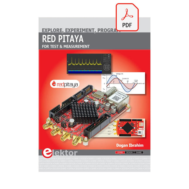
Elektor Digital Red Pitaya for Test and Measurement (E-book)
The Red Pitaya (STEMlab) is a credit card-sized, open-source test and measurement board that can be used to replace most measurement instruments used in electronics laboratories. With a single click, the board can transform into a web-based oscilloscope, spectrum analyser, signal generator, LCR meter, Bode plotter, and microcontroller. The Red Pitaya (STEMlab) can replace the many pieces of expensive measurement equipment found at professional research organisations and teaching laboratories. The device, that based on Linux, includes an FPGA, digital signal processing (DSP), dual core ARM Cortex processor, signal acquisition and generation circuitry, micro USB socket, microSD card slot, RJ45 socket for Ethernet connection, and USB socket – all powered from an external mains adaptor. This book is an introduction to electronics. It aims to teach the principles and applications of basic electronics by carrying out real experiments using the Red Pitaya (STEMlab). The book includes many chapters on basic electronics and teaches the theory and use of electronic components including resistors, capacitors, inductors, diodes, transistors, and operational amplifiers in electronic circuits. Many fun and interesting Red Pitaya (STEMlab) experiments are included in the book. The book also makes an introduction to visual programming environment. The book is written for college level and first year university students studying electrical or electronic engineering.
€ 29,95
Members € 23,96


