Search results for "diy OR kitchen OR scale OR kit OR of OR parts OR 150708 OR 71"
-

Elektor Labs Elektor AM Transmitter Kit
Build Your Own Vintage Radio Broadcaster The Elektor AM Transmitter Kit allows streaming audio to vintage AM radio receivers. Based on a Raspberry Pi Pico microcontroller module, the AM Transmitter can transmit on 32 frequencies in the AM band, from 500 kHz up to 1.6 MHz in 32 steps of approx. 35 kHz. The frequency is selected with a potentiometer and shown on a 0.96" OLED display. A pushbutton allows toggles the transmitting mode between On and Off. The range of the transmitter depends on the antenna. The onboard antenna provides a range of a few centimeters, requiring the AM Transmitter to be placed close to or inside the radio. An external loop antenna (not included) can be connected to increase the range. The Elektor AM Transmitter Kit comes as a kit of parts that you must solder to the board yourself. Features The board is compatible with a Hammond 1593N enclosure (not included).A 5 VDC power supply with micro-USB connector (e.g., an old phone charger) is needed to power the kit (not included). Current consumption is 100 mA. The Arduino software (requiring Earle Philhower’s RP2040 Boards Package) for the Elektor AM Transmitter Kit plus more information is available at the Elektor Labs page of this project. Component List Resistors R1, R4 = 100 Ω R2, R3, R8 = 10 kΩ R5, R6, R9, R10, R11 = 1 kΩ R7 = optional (not included) P1 = potentiometer 100 kΩ, linear Capacitors C1 = 22 µF 16V C2, C4 = 10 nF C3 = 150 pF Miscellaneous K1 = 4×1 pin socket K2, K3 = 3.5 mm socket Raspberry Pi Pico pushbutton, angle mount 0.96" monochrome I²C OLED display PCB 150292-1
€ 34,95€ 29,95
Best Price
-

iFixit iFixit Manta Driver Kit
This kit includes iFixit's widest assortment of bits, complete with every driver head you’ll need to tackle any repair or DIY project. It includes standard bits like Phillips and Flathead in a full range of sizes to handle everything from precision electronics repair to home DIY projects. And it wouldn’t be an iFixit bit set if it didn’t include all the exotic bits from Pentalobes for Apple iPhone and MacBook repair to Gamebits for your vintage Nintendo consoles. All of the next-gen bit sets have been re-designed in order to maximize convenience and usability. The bit set lid is held in place with magnets to increase product lifespan (no more broken hinges or clasps) and also mounts to the back of the bit set case to keep it out of the way while you do your work. If you need help keeping your screws and parts organized, you can use the lid’s integrated sorting tray. The 4 mm bits have been adjusted and have now a longer neck for a deeper and more precise reach. Toolkit Includes Easy-to-Open Magnetized Case Lid with Built-in Sorting Tray 4 mm Aluminum Bit Driver 1/4' Aluminum Bit Driver 4 mm Screwdriver Bits Phillips - 000, 00, 0 Flathead - 1, 1.5, 2, 2.5, 3, 3.5 mm Torx - T2, T3, T4, T5 Torx Security - TR6, TR7, TR8 Pentalobe - P2, P5, P6 JIS - 000, 00, 0, 1 Hex - 0.7, 0.9, 1.3, 1.5 mm Hex Security - 2, 2.5, 3, 3.5 mm Tri-point - Y000, Y00, Y0, Y1 Nut driver - 2.5, 3, 3.5, 4, 4.5, 5, 5.5 mm Gamebit - 3.8, 4.5 mm Spanner - 4, 6 Triangle - 2, 2.2, 2.6, 3 mm Oval Bit iPhone Standoff Bit Sim Eject Bit Magnetic Pickup Bit 1/4' Screwdriver Bits Phillips - 1, 2, 3 Flathead - 4, 5, 6, 7, 8 mm Hex Security - 4, 5, 6, 7, 8 mm Hex Security SAE - 1/8, 9/64, 5/32, 3/16, 7/32, 1/4 Pozidriv - PZ0, PZ1, PZ2, PZ3 Torq-set - 6, 8, 10 Spanner - 8, 10, 12 Square - 0, 1, 2, 3 Spline - M5, M6, M8 Torx Security - TR9, TR10, TR15, TR20, TR25, TR27, TR30, TR35, TR40 Tri-wing 1, 2, 3, 4 Clutch 1, 2, 3 Schrader Valve Hook Drive 1/4' to 4 mm Adapter 1/4' Driver to 1/4' Socket 1/4' Driver to 3/8' Socket 1/4' Socket to 1/4' Driver Specifications Bit Metal: 6150 Steel Driver Material: Anodized Aluminum Case Material: ABS Foam: EVA
€ 64,95
-
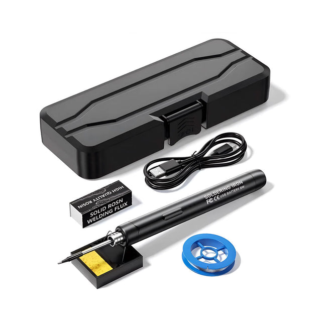
Generic Smart USB Soldering Iron Kit
The Smart USB Soldering Iron Kit is a compact, cordless solution designed for precision and portability. Featuring intelligent three-speed temperature control (300-450°C) with an easy-to-read LED display, it heats up in just 10 seconds and melts solder in as little as 6 seconds. The 1000 mAh rechargeable battery delivers up to 30 minutes of continuous use, making it ideal for quick repairs, electronics projects, and DIY tasks. With a plug-and-play, replaceable tip and a high-temperature-resistant insulated shell, it’s safe, user-friendly, and perfect for both beginners and professionals on the go. Features Three-Speed Intelligent Temperature Adjustment: Features an LED display screen with adjustable temperatures between 300-450°C (572-842°F). Easily switch between Celsius and Fahrenheit. Integrated Plug-In Soldering Iron Tip: Plug-and-play design. The tip can be replaced by simply unscrewing it, ensuring quick and convenient operation. Safe and Durable Design: High-temperature-resistant, insulated shell for enhanced safety during use. Battery Capacity: Equipped with a rechargeable 1000 mAh battery that supports up to 30 minutes of continuous operation on a full charge – ideal for everyday tasks. Efficient Performance: 8 W power with an integrated heating core for rapid heat-up. Melts tin in just 6 seconds, providing excellent thermal conductivity. Easy to Use: After powering on via USB, set your desired temperature. The soldering iron heats up in 10 seconds. Once finished, place the tip on the stand—it cools down within 1 minute. Perfect for beginners, hobbyists, basic home repairs, and training engineers. Cordless Innovation: This cordless soldering kit includes a built-in rechargeable lithium-ion battery, eliminating the need for cables. Versatile use for circuit board soldering, electrical repairs, jewelry making, metal crafts, computer maintenance, and DIY projects. Specifications Adjustable Temperature: 300-450°C (572-842°F) Tin Melting Time: <15 seconds Working Voltage: 5 V Power Output: 8 W Battery Capacity: 1000 mAh Auto Sleep Function: Activates after 10 minutes of inactivity Charging Time: Approx. 90 minutes Battery Life: Up to 30 minutes continuous use Charging Interface: USB-C Main Material: Aluminum alloy Dimensions: 190 x 16 mm (7.4 x 0.6") Included 1x USB Soldering Iron 1x Soldering Tip 1x Soldering Rosin 1x Soldering Iron Holder (with Sponge) 1x USB-C Charging Cable 1x Solder Wire 1x Storage Box
€ 34,95€ 17,50
Best Price
-
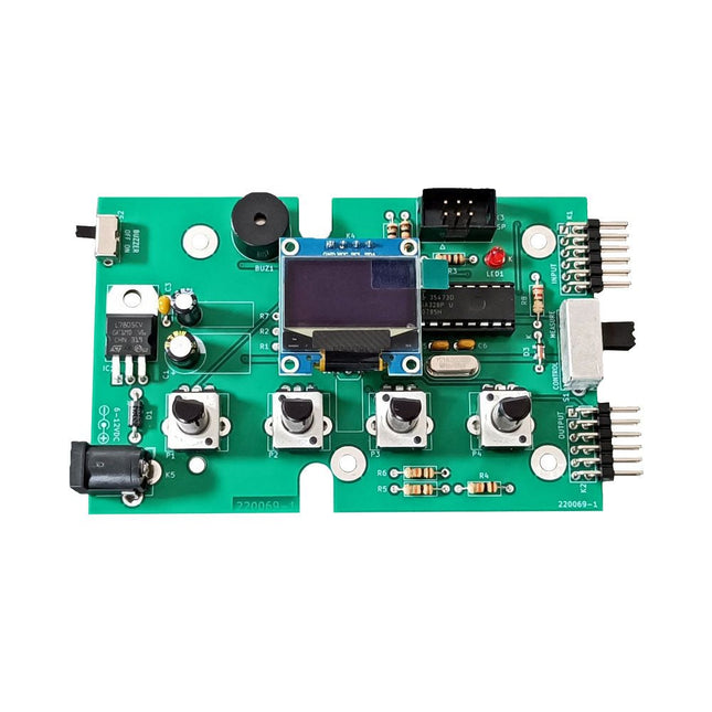
Elektor Labs Elektor Super Servo Tester Kit
The Elektor Super Servo Tester can control servos and measure servo signals. It can test up to four servo channels at the same time. The Super Servo Tester comes as a kit. All the parts required to assemble the Super Servo Tester are included in the kit. Assembling the kit requires basic soldering skills. The microcontroller is already programmed. The Super Servo Tester features two operating modes: Control/Manual and Measure/Inputs. In Control/Manual mode the Super Servo Tester generates control signals on its outputs for up to four servos or for the flight controller or ESC. The signals are controlled by the four potentiometers. In Measure/Inputs the Super Servo Tester measures the servo signals connected to its inputs. These signals may come from for instance an ESC, a flight controller, or the receiver or another device. The signals are also routed to the outputs to control the servos or the flight controller or ESC. The results are shown on the display. Specifications Operating modes Control/Manual & Measure/Inputs Channels 3 Servo signal inputs 4 Servo signal outputs 4 Alarm Buzzer & LED Display 0.96' OLED (128 x 32 pixels) Input voltage on K5 7-12 VDC Input voltage on K1 5-7.5 VDC Input current 30 mA (9 VDC on K5, nothing connected to K1 and K2) Dimensions 113 x 66 x 25 mm Weight 60 g Included Resistors (0.25 W) R1, R3 1 kΩ, 5% R2, R4, R5, R6, R7, R9, R10 10 kΩ, 5% R8 22 Ω, 5% P1, P2, P3, P4 10 kΩ, lin/B, vertical potentiometer Capacitors C1 100 µF 16 V C2 10 µF 25 V C3, C4, C7 100 nF C5, C6 22 pF Semiconductors D1 1N5817 D2 LM385Z-2.5 D3 BZX79-C5V1 IC1 7805 IC2 ATmega328P-PU, programmed LED1 LED, 3 mm, red T1 2N7000 Miscellaneous BUZ1 Piezo buzzer with oscillator K1, K2 2-row, 12-way pinheader, 90° K5 Barrel jack K4 1-row, 4-way pin socket K3 2-row, 6-way boxed pinheader S1 Slide switch DPDT S2 Slide switch SPDT X1 Crystal, 16 MHz 28-way DIP socket for IC2 Elektor PCB OLED display, 0.96', 128 x 32 pixels, 4-pin I²C interface Links Elektor Magazine Elektor Labs
€ 59,95€ 49,95
Best Price
-

Velleman Whadda 3D Xmas Tree Kit
The Whadda 3D Xmas Tree Kit is aimed at hobbyists and beginners who are interested in soldering and electronics. With this DIY kit, you can build a festive LED Christmas tree. Features 16 flashing red LEDs Extra green and yellow LEDs provided to customise your tree Can be hung on and fed through wires Will operate on 12 V DC (e.g. in cars) Specifications Low power consumption 8 mA Power supply 9 V battery operation (not included) Dimensions 102 x 88 x 80 mm Weight 65 g Downloads Manual
€ 10,95
-

Holybro Holybro QAV 250 ARF Drone Kit
The QAV250 Kit is the perfect way to get started developing on either PX4 or Ardupilot. It pairs a carbon fiber 250 racing frame and essential electronics with Pixhawk 6C mini autopilot. The kit is easy to assemble. No soldering needed. Specifications Micro Power Module (PM06 v2) Motors: 2207 KV1950 Wheelbase: 250 mm Dimensions: 198 x 235 x 70 mm Weight: 347 g Included Carbon fiber 250 airframe with hardware Micro Power Module (PM06 v2) Motors: 2207 KV1950 5' Plastic Props Fully assembled Power Management Board with ESCs (BLHeli S ESC 20A) Battery Straps Note: LiPo battery is not included.
€ 214,95
Best Price
-
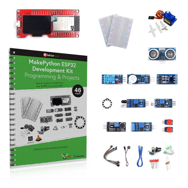
Elektor Bundles MakePython ESP32 Development Kit (EN)
Learn how to use the ESP32 Microcontroller and MicroPython programming in your future projects! The project book, written by well-known Elektor author Dogan Ibrahim, holds many software- and hardware-based projects especially developed for the MakePython ESP32 Development Kit. The kit comes with several LEDs, sensors, and actuators. The kit will help you acquire the basic knowledge to create IoT projects. The book’s fully evaluated projects feature all the supplied components. Each project includes a block diagram, a circuit diagram, a full program listing, and a complete program description. Included in the kit 1x MakePython ESP32 development board with LCD 1x Ultrasonic ranging module 1x Temperature and humidity sensor 1x Buzzer module 1x DS18B20 module 1x Infrared module 1x Potentiometer 1x WS2812 module 1x Sound sensor 1x Vibration sensor 1x Photosensitive resistance module 1x Pulse sensor 1x Servo motor 1x USB cable 2x Button 2x Breadboard 45x Jumper wire 10x Resistor 330R 10x LED (Red) 10x LED (Green) 1x Project book (206 pages) 46 Projects in the Book LED Projects Blinking LED Flashing SOS Blinking LED – using a timer Alternately flashing LEDs Button control Changing the LED flashing rate using pushbutton interrupts Chasing-LEDs Binary-counting LEDs Christmas lights (random-flashing 8 LEDs) Electronic dice Lucky day of the week Pulsewidth Modulation (PWM) Projects Generate a 1000-Hz PWM waveform with 50% duty cycle LED brightness control Measuring the frequency and duty cycle of a PWM waveform Melody maker Simple electronic organ Servo motor control Servo motor DS18B20 thermometer Analog To Digital Converter (ADC) Projects Voltmeter Plotting the analog input voltage ESP32 internal temperature sensor Ohmmeter Photosensitive resistance module Digital To Analog Converter (DAC) Projects Generating fixed voltages Generating a sawtooth-wave signal Generating a triangular-wave signal Arbitrary periodic waveform Generating a sinewave signal Generating accurate sinewave signal using timer interrupts Using The OLED Display Seconds counter Event counter DS18B20 OLED based digital thermometer ON-OFF temperature controller Measuring the temperature and humidity Ultrasonic distance measurement Height of a person (stadiometer) Heart rate (pulse) measurement Other Sensors Supplied with the Kit Theft alarm Sound-activated light Infrared obstacle avoidance with buzzer WS2812 RGB LED ring Timestamping temperature and humidity readings Network Programming Wi-Fi scanner Remote control from the Internet browser (using a smartphone or PC) – Web Server Storing temperature and humidity data in the Cloud Low-Power Operation Using a timer to wake up the processor
€ 89,95€ 69,95
Best Price


-
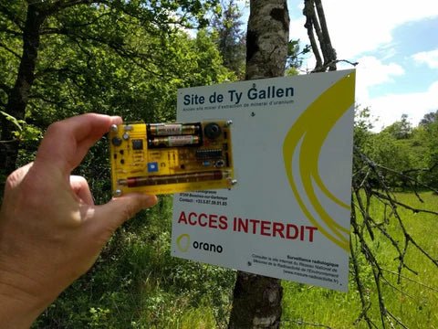
, by Clemens Valens Review: Detect Radiation with the MightyOhm Geiger Counter Kit
The MightyOhm Geiger Counter is a device for detecting beta and gamma radiation levels. Because radiation is so harmful, you may want to keep an...
-

, by Lobna Belarbi Elektor’s Raspberry Pi Bundles: From Beginner-Friendly to Advanced Kits
Find the Perfect Raspberry Pi Bundle for Your Skill Level Whether you're a beginner eager to explore the world of Raspberry Pi or an advanced...
-
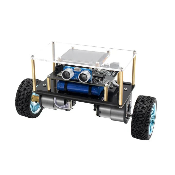
, by Lobna Belarbi Affordable Robot Kits to Kickstart Your Robotics Journey
Robotics is an exciting and rewarding field, but getting started can be intimidating—especially when it comes to choosing the right kit. Fortunately, Elektor offers a...
-

, by Lobna Belarbi Must-Have Boards, Kits & Tools to Start Your Arduino Journey with Elektor
Whether you're a newcomer eager to explore the world of microcontrollers or an experienced maker seeking to expand your toolkit, Elektor offers a curated selection...
-
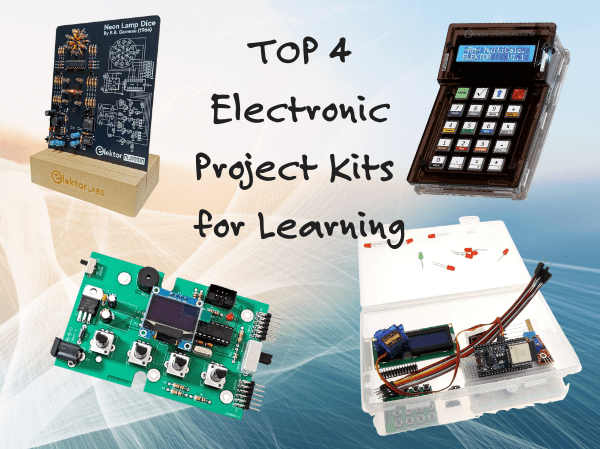
, by Udo Bormann Top 4 Elektor Electronics Project Kits for Learning and Skill Development
Discover four of Elektor’s most exciting electronics kits — from IoT and Arduino to retro logic and motion control. Whether you're just starting out or...


