The flexibility of the Artemis module starts with SparkFun's Arduino core. You can program and use the Artemis module just like you would an Uno or any other Arduino. The time to first blink is just 5 minutes away! We built the core from the ground up, making it fast and as lightweight as possible.
Next is the module itself. Measuring 10 x 15 mm, the Artemis module has all the support circuitry you need to use the fantastic Ambiq Apollo3 processor in your next project. We're proud to say the SparkFun Artemis module is the first open-source hardware module with the design files freely and easily available. We've carefully designed the module so that implementing Artemis into your design can be done with low-cost 2-layer PCBs and 8mil trace/space.
Made in the USA at SparkFun's Boulder production line, the Artemis module is designed for consumer-grade products. This truly differentiates the Artemis from its Arduino brethren. Ready to scale your product? The Artemis will grow with you beyond the Uno footprint and Arduino IDE. Additionally, the Artemis has an advanced HAL (hardware abstraction layer), allowing users to push the modern Cortex-M4F architecture to its limit.
The SparkFun Artemis Module is fully FCC/IC/CE certified and is available in full tape and reel quantities. With 1M flash and 384k RAM, you'll have plenty of room for your code. The Artemis module runs at 48MHz with a 96MHz turbo mode available and with Bluetooth to boot!
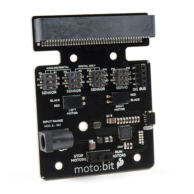
Onboard each moto:bit are multiple I/O pins, as well as a vertical Qwiic connector, capable of hooking up servos, sensors and other circuits. At the flip of the switch, you can get your micro:bit moving! The moto:bit connects to the micro:bit via an updated SMD, edge connector at the top of the board, making setup easy. This creates a handy way to swap out micro:bits for programming while still providing reliable connections to all of the different pins on the micro:bit. We have also included a basic barrel jack on the moto:bit that is capable of providing power to anything you connect to the carrier board. Features More reliable Edge connector for easy use with the micro:bit Full H-Bridge for control of two motors Control servo motors Vertical Qwiic Connector I²C port for extending functionality Power and battery management onboard for the micro:bit
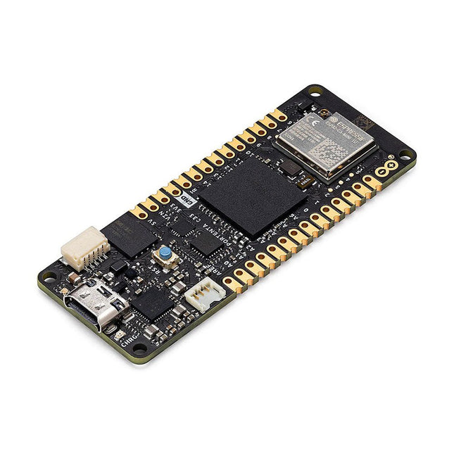
The Portenta C33 is a powerful System-on-Module designed for low-cost Internet of Things (IoT) applications. Based on the R7FA6M5BH2CBG microcontroller from Renesas, this board shares the same form factor as the Portenta H7 and it is backward compatible with it, making it fully compatible with all Portenta family shields and carriers through its high-density connectors.
As a low-cost device, the Portenta C33 is an excellent choice for developers looking to create IoT devices and applications on a budget. Whether you're building a smart home device or a connected industrial sensor, the Portenta C33 provides the processing power and connectivity options you need to get the job done.
Quickly deploying AI-powered projects becomes quick and easy with Portenta C33, by leveraging a vast array of ready-to-use software libraries and Arduino sketches available, as well as widgets that display data in real time on Arduino IoT Cloud-based dashboards.
Features
Ideal for low-cost IoT applications with Wi-Fi/Bluetooth LE connectivity
Supports MicroPython and other high-level programming languages
Offers industrial-grade security at the hardware level and secure OTA firmware updates
Leverages ready-to-use software libraries and Arduino sketches
Perfect to monitor and display real-time data on Arduino IoT Cloud widget-based dashboards
Compatible with Arduino Portenta and MKR families
Features castellated pins for automatic assembly lines
Cost Effective Performance
Reliable, secure and with computational power worthy of its range, Portenta C33 was designed to provide big and small companies in every field with the opportunity to access IoT and benefit from higher efficiency levels and automation.
Applications
Portenta C33 brings more applications than ever within users’ reach, from enabling quick plug-and-play prototyping to providing a cost-effective solution for industrial-scale projects.
Industrial IoT gateway
Machine monitoring to track OEE/OPE
Inline quality control and assurance
Energy consumption monitoring
Appliances control system
Ready-to-use IoT prototyping solution
Specifications
Microcontroller
Renesas R7FA6M5BH2CBG ARM Cortex-M33:
ARM Cortex-M33 core up to 200 MHz
512 kB onboard SRAM
2 MB onboard Flash
Arm TrustZone
Secure Crypto Engine 9
External Memories
16 MB QSPI Flash
USB-C
USB-C High Speed
Connectivity
100 MB Ethernet interface (PHY)
Wi-Fi
Bluetooth Low Energy
Interfaces
CAN
SD Card
ADC
GPIO
SPI
I²S
I²C
JTAG/SWD
Security
NXP SE050C2 Secure Element
Operating Temperatures
-40 to +85°C (-40 to 185°F)
Dimensions
66,04 x 25,40 mm
Downloads
Datasheet
Schematics
The ATmega328 Uno Development Board (Arduino Uno compatible) is a microcontroller board based on the ATmega328.
It has 14 digital input/output pins (of which 6 can be used as PWM outputs), 6 analogue inputs, a 16 MHz ceramic resonator, a USB connection, a power jack, an ICSP header and a reset button.
It contains everything needed to support the microcontroller; connect it to a computer with a USB cable or power it with a AC-to-DC adapter or battery to get started.
Specifications
Microcontroller
ATmega328
Operating voltage
5 V DC
Input voltage (recommended)
7-12 V DC
Input voltage (limits)
6-20 V DC
Digital I/O pins
14 (of which 6 provide PWM output)
Analogue input pins
6
SRAM
2 kB (ATmega328)
EEPROM
1 kB (ATmega328)
Flash memory
32 kB (ATmega328) of which 0.5 kB used by bootloader
Clock speed
16 MHz
Downloads
Manual
This ultrasonic distance sensor (ME007-ULA V1) offers high performance with a robust, waterproof probe. Operating on the principle of ultrasonic echo ranging, the sensor determines the distance to a target by measuring the time elapsed between sending a pulse and receiving the echo. Its non-contact design allows it to detect a wide range of materials, including transparent or non-ferrous objects, metals, non-metals, liquids, solids, and powders.
Specifications
Detecting Distance
27~800 cm
Output Interface
RS232, Voltage Analog
Operating Voltage
5-12 V
Average Current
<10 mA
Operating Temperature
−15~60°C
Dimensions
60 x 43 x 31 mm
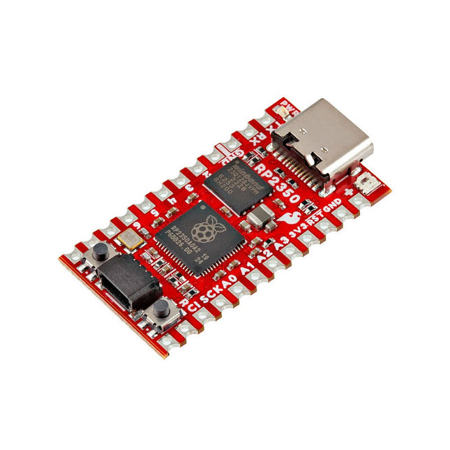
The SparkFun RP2350 Pro Micro provides a powerful development platform, built around the RP2350 microcontroller. This board uses the updated Pro Micro form factor. It includes a USB-C connector, Qwiic connector, WS2812B addressable RGB LED, Boot and Reset buttons, resettable PTC fuse, and PTH and castellated solder pads.
The RP2350 is a unique dual-core microcontroller with two ARM Cortex-M33 processors and two Hazard3 RISC-V processors, all running at up to 150 MHz! Now, this doesn't mean the RP2350 is a quad-core microcontroller. Instead, users can select which two processors to run on boot instead. You can run two processors of the same type or one of each. The RP2350 also features 520 kB SRAM in ten banks, a host of peripherals including two UARTs, two SPI and two I²C controllers, and a USB 1.1 controller for host and device support.
The Pro Micro also includes two expanded memory options: 16 MB of external Flash and 8 MB PSRAM connected to the RP2350's QSPI controller. The RP2350 Pro Micro works with C/C++ using the Pico SDK, MicroPython, and Arduino development environments.
Features
RP2350 Microcontroller
8 MB PSRAM
16 MB Flash
Supply Voltage
USB: 5 V
RAW: 5.3 V (max.)
Pro Micro Pinout
2x UART
1x SPI
10x GPIO (4 used for UART1 and UART0)
4x Analog
USB-C Connector
USB 1.1 Host/Device Support
Qwiic Connector
Buttons
Reset
Boot
LEDs
WS2812 Addressable RGB LED
Red Power LED
Dimensions: 33 x 17.8 mm
Downloads
Schematic
Eagle Files
Board Dimensions
Hookup Guide
RP2350 MicroPython Firmware (Beta 04)
SparkFun Pico SDK Library
Arduino Pico Arduino Core
Datasheet (RP2350)
Datasheet (APS6404L PSRAM)
RP2350 Product Brief
Raspberry Pi RP2350 Microcontroller Documentation
Qwiic Info Page
GitHub Repository
The CubeCell series is designed primarily for LoRa/LoRaWAN node applications.
Built on the ASR605x platform (ASR6501, ASR6502), these chips integrate the PSoC 4000 series MCU (ARM Cortex-M0+ Core) with the SX1262 module. The CubeCell series offers seamless Arduino compatibility, stable LoRaWAN protocol operation, and straightforward connectivity with lithium batteries and solar panels.
The HTCC-AB02S is a developer-friendly board with an integrated AIR530Z GPS module, ideal for quickly testing and validating communication solutions.
Features
Arduino compatible
Based on ASR605x (ASR6501, ASR6502), those chips are already integrated the PSoC 4000 series MCU (ARM Cortex M0+ Core) and SX1262
LoRaWAN 1.0.2 support
Ultra low power design, 21 uA in deep sleep
Onboard SH1.25-2 battery interface, integrated lithium battery management system (charge and discharge management, overcharge protection, battery power detection, USB/battery power automatic switching)
Good impendence matching and long communication distance
Onboard solar energy management system, can directly connect with a 5.5~7 V solar panel
Micro USB interface with complete ESD protection, short circuit protection, RF shielding, and other protection measures
Integrated CP2102 USB to serial port chip, convenient for program downloading, debugging information printing
Onboard 0.96-inch 128x64 dot matrix OLED display, which can be used to display debugging information, battery power, and other information
Using Air530 GPS module with GPS/Beidou Dual-mode position system support
Specifications
Main Chip
ASR6502 (48 MHz ARM Cortex-M0+ MCU)
LoRa Chipset
SX1262
Frequency
863~870 MHz
Max. TX Power
22 ±1 dBm
Max. Receiving Sensitivity
−135 dBm
Hardware Resource
2x UART1x SPI2x I²C1x SWD3x 12-bit ADC input8-channel DMA engine16x GPIO
Memory
128 Kb FLASH16 Kb SRAM
Power consumption
Deep sleep 21 uA
Interfaces
1x Micro USB1x LoRa Antenna (IPEX)2x (15x 2.54 Pin header) + 3x (2x 2.54 Pin header)
Battery
3.7 V lithium battery (power supply and charging)
Solar Energy
VS pin can be connected to 5.5~7 V solar panel
USB to Serial Chip
CP2102
Display
0.96" OLED (128 x 64)
Operating temperature
−20~70°C
Dimensions
55.9 x 27.9 x 9.5 mm
Included
1x CubeCell HTCC-AB02S Development Board
1x Antenna
1x 2x SH1.25 battery connector
Downloads
Datasheet
Schematic
GPS module (Manual)
Quick start
GitHub
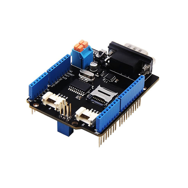
Features Implements CAN V2.0B at up to 1 Mb/s Industrial standard 9 pin sub-D connector OBD-II and CAN standard pinout selectable. Changeable chip select pin Changeable CS pin for TF card slot Changeable INT pin Screw terminal that easily to connect CAN_H and CAN_L Arduino Uno pin headers Micro SD card holder 2 Grove connectors (I2C and UART) SPI Interface up to 10 MHz Standard (11 bit) and extended (29 bit) data and remote frames Two receive buffers with prioritized message storage
Pico Breakout Garden Base sits underneath your Pico and lets you connect up to six of our extensive selection of Pimoroni breakouts to it. Whether it's environmental sensors so you can keep track of the temperature and humidity in your office, a whole host of little screens for important notifications and readouts, and, of course, LEDs. Scroll down for a list of breakouts that are currently compatible with our C++/MicroPython libraries!As well as a labelled landing area for your Pico, there's also a full set of broken out Pico connections, in case you need to attach even more sensors, wires, and circuitry. We've thrown in some rubber feet to keep the base nice and stable and to stop it from scratching your desk, or there are M2.5 mounting holes at the corners so that you can bolt it onto a solid surface if you prefer.The six sturdy black slots are edge connectors that connect the breakouts to the pins on your Pico. There's two slots for SPI breakouts, and four slots for I²C breakouts. Because I²C is a bus, you can use multiple I²C devices at the same time, providing they don't have the same I²C address (we've made sure that all of our breakouts have different addresses, and we print them on the back of the breakouts so they're easy to find).As well as being a handy way to add functionality to your Pico, Breakout Garden is also very useful for prototyping projects without the need for complicated wiring, soldering, or breadboards, and you can grow or change up your setup at any time.Features
Six sturdy edge-connector slots for breakouts
4x I²C slots (5 pins)
2x SPI slot (7 pins)
Landing area with female headers for Raspberry Pi Pico
0.1” pitch, 5 or 7 pin connectors
Broken-out pins
Reverse polarity protection (built into breakouts)
99% assembled – just need to stick on the feet!
Compatible with Raspberry Pi Pico
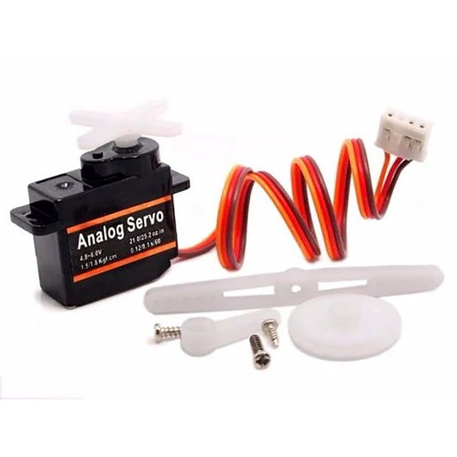
Grove-Servo is a rotary actuator that allows for precise control of the angular position. It's suitable for use in closed-loop systems where precise position control is needed. We regulated the three-wire servo into a Grove standard connecter. You can plug and play it as a typical Grove module now, without jumper wires clutter.
Features
High Accuracy: closed-loop control of position, speed and torque is achieved
High Stability: stable operation at a low speed of 0.12/0.16s/60°
Easy to use: compatible with Grove port, just plug-and-play
Features Integrated Cold-Junction Compensation Supported Types (designated by NIST ITS-90): Type K, J, T, N, S, E, B and R Four Programmable Temperature Alert Outputs: Monitor Hot- or Cold-Junction Temperatures Detect rising or falling temperatures Up to 255°C of Programmable Hysteresis Programmable Digital Filter for Temperature Low Power Dimensions: 20 mm x 40 mm x 18 mm Weight: 18 g Application Petrochemical Thermal Management Hand-Held Measurement Equipment Industrial Equipment Thermal Management Ovens Industrial Engine Thermal Monitor Temperature Detection Racks Downloads Eagle Files Github library Datasheet
The Challenger RP2040 NFC is a small embedded computer, equipped with an advanced on-board NFC controller (NXP PN7150), in the popular Adafruit Feather form factor. It is based on an RP2040 microcontroller chip from the Raspberry Pi Foundation which is a dual-core Cortex-M0 that can run on a clock up to 133 MHz.
NFC
The PN7150 is a full featured NFC controller solution with integrated firmware and NCI interface designed for contactless communication at 13.56 MHz. It is fully compatible with NFC forum requirements and is greatly designed based on learnings from previous NXP NFC device generation. It is the ideal solution for rapidly integrating NFC technology in any application, especially small embedded systems reducing Bill of Material (BOM).
The integrated design with full NFC forum compliancy gives the user all the following features:
Embedded NFC firmware providing all NFC protocols as pre-integrated feature.
Direct connection to the main host or microcontroller, by I²C-bus physical and NCI protocol.
Ultra-low power consumption in polling loop mode.
Highly efficient integrated power management unit (PMU) allowing direct supply from a battery.
Specifications
Microcontroller
RP2040 from Raspberry Pi (133 MHz dual-core Cortex-M0)
SPI
One SPI channels configured
I²C
Two I²C channel configured (dedicated I²C for the PN7150)
UART
One UART channel configured
Analog inputs
4 analog input channels
NFC module
PN7150 from NXP
Flash memory
8 MB, 133 MHz
SRAM memory
264 KB (divided into 6 banks)
USB 2.0 controller
Up to 12 MBit/s full speed (integrated USB 1.1 PHY)
JST Battery connector
2.0 mm pitch
On board LiPo charger
450 mA standard charge current
Dimensions
51 x 23 x 3,2 mm
Weight
9 g
Note: Antenna is not included.
Downloads
Datasheet
Quick start example
The JOY-iT R301T fingerprint sensor module is capable of image collection and algorithm calculation due to this integrated chip. Another remarkable function of the sensor is, that it can recognize the fingerprint in different conditions, for example humidity, light texture or changes of the skin. This offers a very wide range of possible applications to secure locks and doors among others. The chip can send data via UART, TTL serial and USB to the connected controller.
Specifications
Model
JP2000 sensor
Chip
32 Bit ARM Cortex-M3
Chip storage
96 kB RAM, 1 MB Flash
Power supply
4.2-6.0 V
Working current
Typical: 40 mAPeak: 50 mA
Logic level
3,3/5 V TTL Logic
Fingerprint storage capacity
3000 Prints
Matching mode
1:N Identification1:1 Verification
Adjustable security level
1 - 5 levels(default security level: 3)
False acceptance rate
< 0.001%(on security level 3)
False acceptance rate
< 0.1%(on security level 3)
Response time
Pre-treatment: < 0.45 sMatch: < 1.5 s
Baud rate support
9600 - 921600
UART communication
No parity, Stop Bit: 1
Dimensions
42 x 19 x 8 mm
Included
1x Fingerprint sensor COM-FP-R301T
1x Cable
Downloads
Datasheet
Manual
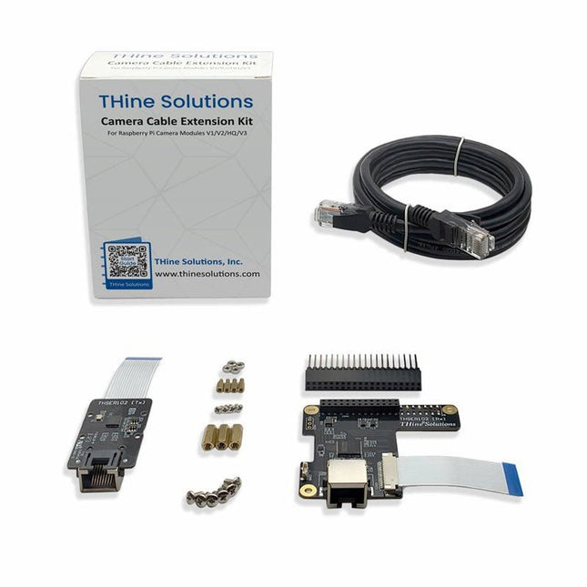
THSER102 is a plug-and-play cable extension kit for Raspberry Pi Camera Modules. The kit is compatible with Raspberry Pi Camera Module 3, in addition to Camera V2 (version 2.1), HQ/Global Shutter Camera, and defined modes of the Raspberry Pi Camera Module V1.3.
The THSER102 extends the cable length for >10 meters between the Raspberry Pi Camera Module and the Computer with a standard LAN Cable.
There is no need for software or coding. THSER102 works as if the Raspberry Pi Camera were directly connected to the computer.
The THSER102 also supports advanced applications. HAT on HAT support allows to use another HAT board on top of THSER102 Rx Board. 3ch GPIO Extension allows extending GPIO communication between the camera location and the computer.
Features
Supporting all Raspberry Pi Camera Modules including Camera Module 3
>10-meter Cable Extension
Plug and Play
No software configuration is needed.
Camera works as if THSER102 not exists.
Advanced Applications Supported
HAT on HAT
3ch GPIO Extension
Included
1x Tx Board
1x Rx Board
1x LAN Cable (2 m)
2x Flat Flex Cables
1x Pin Header
6x Mounting Screws for Rx Board
3x Longer Spacers for Rx Board
4x Mounting screws for Tx Board (for Camera V2 only)
4x Shorter Spacers for Tx Board (for Camera V2 only)
4x Mounting Nuts for Tx Board (for Camera V2 only)
Downloads
Datasheet
The GrovePi+ is an easy-to-use and modular system for hardware hacking with the Raspberry Pi, no need for soldering or breadboards: plug in your Grove sensors and start programming directly.
Grove is an easy-to-use collection of more than 100 inexpensive plug-and-play modules that sense and control the physical world. By connecting Grove Sensors to Raspberry Pi, it empowers your Pi in the physical world. With hundreds of sensors to choose from Grove families, the possibilities for interaction are endless.
Set-up in 4 simple steps
Slip the GrovePi+ board over your Raspberry Pi
Connect the Grove modules to the GrovePi+ board
Upload your program to Raspberry Pi
Begin taking in the world data
The SparkFun MicroMod mikroBUS Carrier Board takes advantage of the MicroMod, Qwiic, and mikroBUS ecosystems making it easy to rapidly prototype with each of them, combined. The MicroMod M.2 socket and mikroBUS 8-pin header provide users the freedom to experiment with any Processor Board in the MicroMod ecosystem and any Click board in the mikroBUS ecosystem, respectively. This board also features two Qwiic connectors to seamlessly integrate hundreds of Qwiic sensors and accessories into your project. The mikroBUS socket comprises a pair of 8-pin female headers with a standardized pin configuration. The pins consist of three groups of communications pins (SPI, UART and I²C), six additional pins (PWM, Interrupt, Analog input, Reset and Chip select), and two power groups (3.3 V and 5 V). While a modern USB-C connector makes programming easy, the Carrier Board is also equipped with a MCP73831 Single-Cell Lithium-Ion/Lithium-Polymer Charge IC so you can charge an attached single-cell LiPo battery. The charge IC receives power from the USB connection and can source up to 450 mA to charge an attached battery. Features M.2 MicroMod (Processor Board) Connector USB-C Connector 3.3 V 1 A Voltage Regulator 2x Qwiic Connectors mikroBUS Socket Boot/Reset Buttons Charge Circuit JTAG/SWD PTH Pins Downloads Schematic Eagle Files Board Dimensions Hookup Guide Getting Started with Necto Studio mikroBUS Standard Qwiic Info Page GitHub Hardware Repo
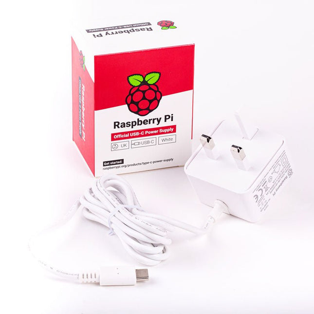
The Raspberry Pi USB-C power supply is designed specifically to power the latest Raspberry Pi 4 Model B computers.
The power supply features a USB-C cable and is available in four different models to suit different international power sockets, and in two colors.
Specifications
Output
Output voltage
+5.1 V DC
Minimum load current
0 A
Nominal load current
3.0 A
Maximum power
15.3 W
Load regulation
±5 %
Line regulation
±2 %
Ripple & noise
120 mVp-p
Rise time
100 ms maximum to regulation limits for DC outputs
Turn-on delay
3000 ms maximum at nominal input AC voltage and full load
Protection
Short circuit protectionOvercurrent protectionOver temperature protection
Efficiency
81% minimum (output current from 100%, 75%, 50%, 25%)72% minimum at 10% load
Output cable
1.5 m 18AWG
Output connector
USB Type-C
Input
Voltage range
100-240 VAC (rated)96-264 VAC (operating)
Frequency
50/60 Hz ±3 Hz
Current
0.5 A maximum
Power consumption (no load)
0.075 W maximum
Inrush current
No damage shall occur, and the input fuse shall not blow
Operating ambient temperature
0-40°C
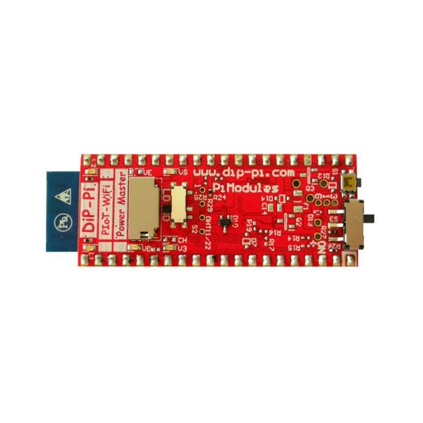
The DiP-Pi WiFi Master is an Advanced WiFi connectivity System with sensors embedded interfaces that cover most of possible needs for IoT application based on Raspberry Pi Pico. It is powered directly from the Raspberry Pi Pico VBUS. The DiP-Pi WiFi Master contains Raspberry Pi Pico embedded RESET button as also ON/OFF Slide Switch that is acting on Raspberry Pi Pico Power Sources.
The DiP-Pi WiFi Master is equipped with WiFi ESP8266 Clone module with embedded antenna. This feature open a wide range of IoT applications based on it.
In Addition to all above features DiP-Pi WiFi Master is equipped with embedded 1-wire, DHT11/22 sensors, and micro–SD Card interfaces. Combination of the extended powering, battery, and sensors interfaces make the DiP-Pi WiFi Master ideal for IoT applications like data logger, plants monitoring, refrigerators monitoring etc.
DiP-Pi WiFi Master is supported with plenty of ready to use examples written in Micro Python or C/C++.
Specifications
General
Dimensions 21 x 51 mm
Raspberry Pi Pico pinout compatible
Independent Informative LEDs (VBUS, VSYS, V3V3)
Raspberry Pi Pico RESET Button
ON/OFF Slide Switch acting on Raspberry Pi Pico Powering Source
Embedded 3.3 V @ 600 mA LDO
ESP8266 Clone WiFi Connectivity
ESP8266 Firmware Upload Switch
Embedded 1-wire Interface
Embedded DHT-11/22 Interface
Powering Options
Raspberry Pi Pico micro-USB (via VBUS)
Embedded Peripherals and Interfaces
Embedded 1-wire interface
Embedded DHT-11/22 Interface
Micro SD Card Socket
Programmer Interface
Standard Raspberry Pi Pico C/C++
Standard Raspberry Pi Pico Micro Python
Case Compatibility
DiP-Pi Plexi-Cut Case
Informative LEDs
VB (VUSB)
VS (VSYS)
V3 (V3V3)
System Protection
Direct Raspberry Pi Pico Hardware Reset Button
PPTC 500 mA @ 18 V fuse on EPR
EPR/LDO Over Temperature protection
EPR/LDO Over Current protection
System Design
Designed and Simulated with PDA Analyzer with one of the most advanced CAD/CAM Tools – Altium Designer
Industrial Originated
PCB Construction
2 ozcopper PCB manufactured for proper high current supply and cooling
6 mils track/6 mils gap technology 2 layers PCB
PCB Surface Finishing – Immersion Gold
Multi-layer Copper Thermal Pipes for increased System Thermal Response and better passive cooling
Downloads
Datasheet
Manual
SMA Straight Plug to SMA Straight Plug, 76.2 mm
Specifications
Frequency range
0 to 18 GHz VSWR (≤1.35)
Insertion loss
≤0,22 db
Body
Brass Nickel
Centre contact
Brass Gold
Insulator
PTFE
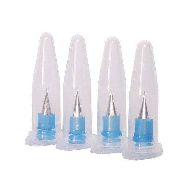
If you want to push the resolution limits of the V-One, these dispensing tips will help enable your experimental projects. This pack contains 4 extra fine nozzles with an internal diameter of 0.150 mm (6 mil).
Do not use with solder paste! It will clog!
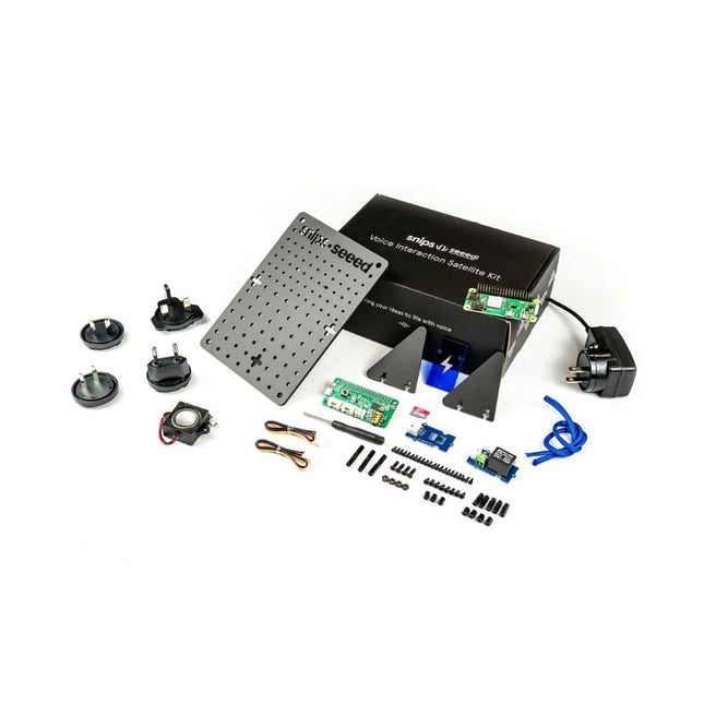
The Voice Interaction Satellite Kit can extend the reach of your base station to each room in your house and enable you to interact with the hardware based on where you issue your commands! You can arrange multiple Satellite Kits throughout your home to add new functionality to Base kit or any other smart speaker, extending your voice control across several rooms.
The Voice Interaction Satellite Kit is powered by a Raspberry Pi Zero W and the ReSpeaker 2-Mics Pi HAT. Along with the kit comes a speaker, a Grove - Temperature Humidity Sensor (SHT31) sensor, a Grove Relay, and a pegboard to hang it on a wall or create a nifty stand.
Note
All Satellite Kits require a Base kit or Raspberry Pi in order to operate as intended.
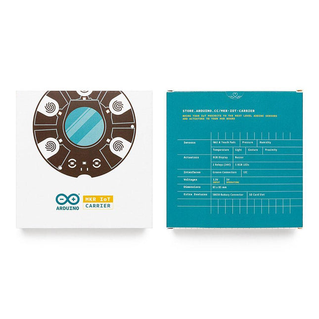
The MKR IoT Carrier comes equipped with 5 RGB LEDs, 5 capacitive touch buttons, a colored display, IMU and a variety of quality sensors. It also features a battery holder for a 18650 Li-Ion battery, SD card holder and Grove connectors.
Data Capture: Map the environment around the carrier using the integrated temperature, humidity, and pressure sensors and collect data about movement using the 6 axis IMU and light, gesture, and proximity sensors. Easily add more external sensors to capture more data from more sources via the on-board Grove connectors (x3).
Data Storage: Capture and store all the data locally on an SD card, or connect to the Arduino IoT Cloud for real-time data capture, storage, and visualization.
Data Visualisation: Locally view real-time sensor readings on the built-in OLED Color Display and create visual or sound prompts using the embedded LEDs and buzzer.
Total Control: Directly control small-voltage electronic appliances using the onboard relays and the five tactile buttons, with the integrated display providing a handy on-device interface for immediate control.
Arduino MKR NB 1500 allows you to build your next smart project.
Ever wanted an automated house? Or a smart garden? Well, now it’s easy with the Arduino IoT Cloud compatible boards. It means: you can connect devices, visualize data, control and share your projects from anywhere in the world. Whether you’re a beginner or a pro, we have a wide range of plans to make sure you get the features you need.
Add Narrowband communication to your project with the MKR NB 1500. It's the perfect choice for devices in remote locations without an Internet connection, or in situations in which power isn't available like on-field deployments, remote metering systems, solar-powered devices, or other extreme scenarios.
The board's main processor is a low power ARM Cortex-M0 32-bit SAMD21, like in the other boards within the Arduino MKR family. The Narrowband connectivity is performed with a module from u-blox, the SARA-R410M-02B, a low power chipset operating in the de different bands of the IoT LTE cellular range. On top of those, secure communication is ensured through the Microchip ECC508 crypto chip. Besides that, the pcb includes a battery charger, and a connector for an external antenna.
This board is designed for global use, providing connectivity on LTE's Cat M1/NB1 bands 1, 2, 3, 4, 5, 8, 12, 13, 18, 19, 20, 25, 26, 28. Operators offering service in that part of the spectrum include: Vodafone, AT&T, T-Mobile USA, Telstra, and Verizon, among others.
Specifications
The Arduino MKR NB 1500 is based on the SAMD21 microcontroller.
Microcontroller
SAMD21 Cortex-M0+ 32-bit low power ARM MCU (datasheet)
Radio module
u-blox SARA-R410M-02B (datasheet summary)
Secure element
ATECC508 (datasheet)
Board power supply (USB/VIN)
5 V
Supported battery
Li-Po Single Cell, 3.7 V, 1500 mAh Minimum
Circuit operating voltage
3.3 V
Digital I/O pins
8
PWM pins
13 (0 .. 8, 10, 12, 18 / A3, 19 / A4)
UART
1
SPI
1
I²C
1
Analog input pins
7 (ADC 8/10/12 bit)
Analog output pins
1 (DAC 10 bit)
External interrupts
8 (0, 1, 4, 5, 6, 7, 8, 16 / A1, 17 / A2)
DC current per I/O pin
7 mA
Flash memory
256 KB (internal)
SRAM
32 KB
EEPROM
No
Clock speed
32.768 kHz (RTC), 48 MHz
LED_BUILTIN
6
USB
Full-speed USB device and embedded host
Antenna gain
2 dB
Carrier frequency
LTE bands 1, 2, 3, 4, 5, 8, 12, 13, 18, 19, 20, 25, 26, 28
Power class (radio)
LTE Cat M1 / NB1: Class 3 (23 dBm)
Data rate (LTE M1 halp-duplex)
UL 375 kbps / DL 300 kbps
Data rate (LTE NB1 full-duplex)
UL 62.5 kbps / DL 27.2 kbps
Working region
Multiregion
Device location
GNSS via modem
Power consumption (LTE M1)
min 100 mA / max 190 mA
Power consumption (LTE NB1)
min 60 mA / max 140 mA
SIM card
MicroSIM (not included with the board)
Dimensions
67.6 x 25 mm
Weight
32 g
Downloads
Eagle Files
Schematics
Pinout
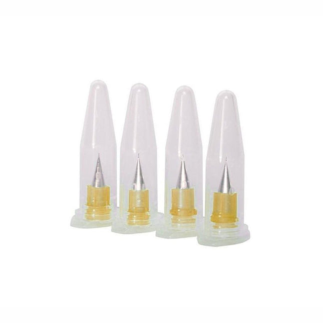
Looking to dispense materials with a lower viscosity? These are the nozzles for you. Don't use this with our standard ink or solder paste... that will result in poor performance.
This pack contains 4 extra fine nozzles with an internal diameter of 0.100 mm (4 mil).