The Speaker Kit for Raspberry Pi is a small amplified speaker designed for the Raspberry Pi.
Included
MonkMakes Amplified Speaker
Set of 10 female to female header wires
Short stereo audio lead
Raspberry Leaf GPIO template
Downloads
Instructions
Datasheet
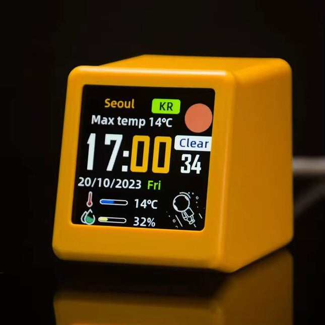
This portable WiFi weather station is the perfect blend of functionality and style, offering real-time updates on temperature, humidity, and time – all at a single glance.
Featuring a clear digital display, the station ensures that weather and time data are always easy to read and understand. Its minimalist design integrates seamlessly into any environment, adding a touch of modern sophistication without drawing unnecessary attention.
Features
Multi-Function Display: Shows weather, atmospheric pressure, min/max temperature, wind speed, city, country/region, date, day of the week, outdoor temperature & humidity – all at a glance.
Custom GIF Animations: Upload your own GIFs for a personalized display experience.
WiFi Connectivity: Automatically connects to the Internet to retrieve real-time weather and time data.
Power Supply: USB-C
Durable Plastic Casing
Dimensions: 45 x 35 x 40 mm
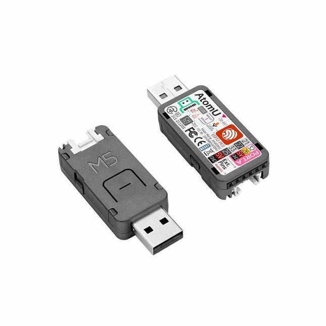
ATOM U is a compact low-power consumption speech recognition IoT development kit. It adopts an ESP32 chipset, equipped with 2 low-power Xtensa 32-bit LX6 microprocessors with the main frequency of up to 240 MHz. Built-in USB-A interface, IR emitter, programmable RGB LED. Plug-and-play, easy to upload and download programs. Integrated Wi-Fi and digital microphone SPM1423 (I2S) for the clear sound record. suitable for HMI, Speech-to-Text (STT). Low-code development ATOM U supports UIFlow graphical programming platform, scripting-free, cloud push; Fully compatible with Arduino, MicroPython, ESP32-IDF, and other mainstream development platforms, to quickly build various applications. High integration ATOM U contains a USB-A port for programming/power supply, IR emitter, programmable RGB LED x1, button x1; Finely tuned RF circuit, providing stable and reliable wireless communication. Strong expandability ATOM U is easy access to M5Stack's hardware and software system. Features ESP32-PICO-D4 (2.4GHz Wi-Fi dual mode) Integrated programmable RGB LED and button Compact design Built-in IR emitter Expandable pinout and GROVE port Development platform: UIFlow MicroPython Arduino Specifications ESP32-PICO-D4 240MHz dual core, 600 DMIPS, 520KB SRAM, 2.4G Wi-Fi Microphone SPM1423 Microphone sensitivity 94 dB SPL@1 KHz Typical value: -22 dBFS Microphone signal-to-noise ratio 94 dB SPL@1 KHz, A-weighted Typical value: 61.4 dB Standby working current 40.4 mA Support input sound frequency 100 Hz ~ 10 KHz Support PDM clock frequency 1.0 ~ 3.25 MHz Weight 8.4 g Product size 52 x 20 x 10 mm Downloads Documentation
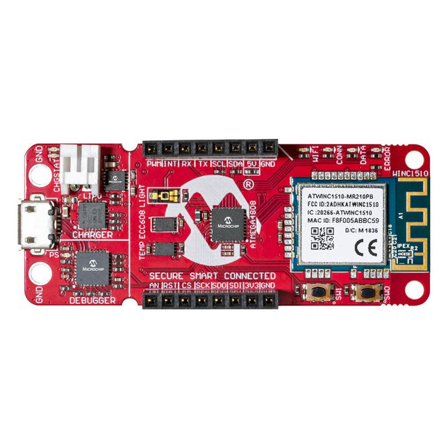
The AVR-IoT WA development board combines a powerful ATmega4808 AVR MCU, an ATECC608A CryptoAuthentication secure element IC and the fully certified ATWINC1510 Wi-Fi network controller – which provides the most simple and effective way to connect your embedded application to Amazon Web Services (AWS). The board also includes an on-board debugger, and requires no external hardware to program and debug the MCU.
Out of the box, the MCU comes preloaded with a firmware image that enables you to quickly connect and send data to the AWS platform using the on-board temperature and light sensors. Once you are ready to build your own custom design, you can easily generate code using the free software libraries in Atmel START or MPLAB Code Configurator (MCC).
The AVR-IoT WA board is supported by two award-winning Integrated Development Environments (IDEs) – Atmel Studio and Microchip MPLAB X IDE – giving you the freedom to innovate with your environment of choice.
Features
ATmega4808 microcontroller
Four user LED’s
Two mechanical buttons
mikroBUS header footprint
TEMT6000 Light sensor
MCP9808 Temperature sensor
ATECC608A CryptoAuthentication™ device
WINC1510 WiFi Module
On-board Debugger
Auto-ID for board identification in Atmel Studio and Microchip MPLAB X
One green board power and status LED
Programming and debugging
Virtual COM port (CDC)
Two DGI GPIO lines
USB and battery powered
Integrated Li-Ion/LiPo battery charger
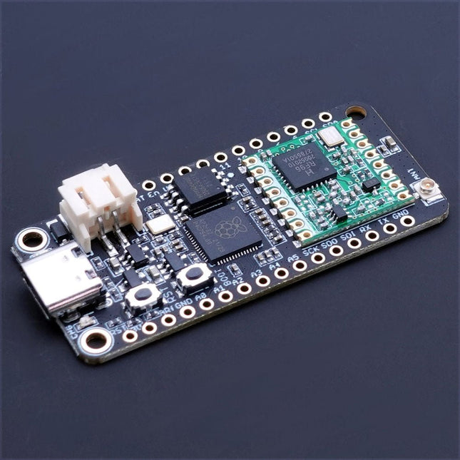
The Challenger RP2040 LoRa is an Arduino/CircuitPython compatible Adafruit Feather format microcontroller board based on the Raspberry Pi Pico (RP2040) chip.
The transceiver features a LoRa long range modem that provides ultra-long range spread spectrum communication and high interference immunity whilst minimizing current consumption.
LoRa
The integrated module LoRa module (RFM95W) can achieve a sensitivity of over -148 dBm utilizing a low cost crystal and bill of materials. The high sensitivity combined with the integrated +20 dBm power amplifier yields industry leading link budget making it optimal for any application requiring range or robustness. LoRa also provides significant advantages in both blocking and selectivity over conventional modulation techniques, solving the traditional design compromise between range, interference immunity and energy consumption.
The RFM95W is connected to the RP2040 via SPI channel 1 and a few GPIO’s that is required for signaling. A U.FL connector is used to attach your LoRa antenna to the board.
168 dB maximum link budget
+20 dBm – 100 mW constant RF output vs. V supply
+14 dBm high efficiency PA
Programmable bit rate up to 300 kbps
High sensitivity: down to -148 dBm
Bullet-proof front end: IIP3 = -12.5 dBm
Excellent blocking immunity
Low RX current of 10.3 mA, 200 nA register retention
Fully integrated synthesizer with a resolution of 61 Hz
FSK, GFSK, MSK, GMSK, LoRaTM and OOK modulation
Built-in bit synchronizer for clock recovery
Preamble detection
127 dB Dynamic Range RSSI
Automatic RF Sense and CAD with ultra-fast AFC
Packet engine up to 256 bytes with CRC
Specifications
Microcontroller
RP2040 from Raspberry Pi (133 MHz dual-core Cortex-M0)
SPI
Two SPI channels configured (second SPI connected to RFM95W)
I²C
One I²C channel configured
UART
One UART channel configured
Analog inputs
4 analog input channels
Radio module
RFM95W from Hope RF
Flash memory
8 MB, 133 MHz
SRAM memory
264 KB (divided into 6 banks)
USB 2.0 controller
Up to 12 MBit/s full speed (integrated USB 1.1 PHY)
JST Battery connector
2.0 mm pitch
On board LiPo charger
450 mA standard charge current
Dimensions
51 x 23 x 3,2 mm
Weight
9 g
Downloads
Datasheet
Design files
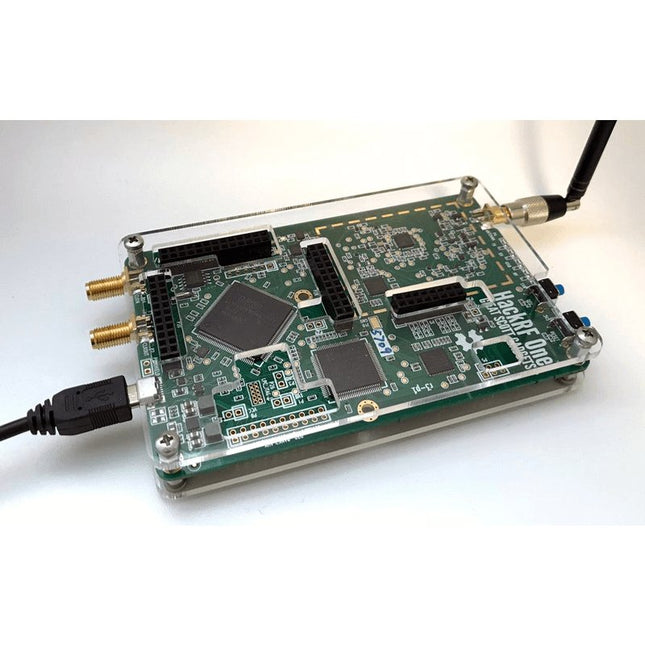
This clear acrylic case is the official case for the HackRF One board. It can replace the standard black plastic case of the HackRF One.
Assembly Instructions
Use a guitar pick or spudger to extract the HackRF One circuit board from the black plastic case.
Insert one long screw into each corner of the bottom acrylic panel. Secure each long screw with a short (5 mm) spacer on the opposite side of the panel.
Place the HackRF One circuit board (facing up) on top of the bottom panel, fitting the ends of the long screws through the corner mounting holes of the circuit board.
Secure the circuit board with one long (6 mm) spacer in each corner.
Place the top acrylic panel on top of the circuit board, aligning the cutouts with the circuit board’s expansion headers.
Secure each corner with a short screw.
Note: Do not overtighten! Hand-tighten only at every step.
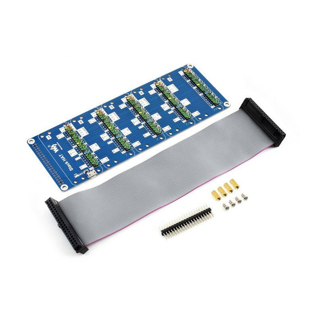
This is an I/O expansion kit designed for Raspberry Pi, which provides 5 sets of 2x20 pinheaders, that means a handy way to 'stack' multi different HATs together, and use them as a specific combination / project.
Features
Standard Raspberry Pi connectivity, directly pluggable OR through ribbon cable
5 sets of 2x20 pinheaders, connect multi HATs together
USB external power port, provides enough power supply for multi HATs
Clear and descriptive pin labels for easy use
Reserved jumper pads on the bottom side, pin connections are changeable by soldering, to avoid pin conflicts
Note: make sure there are no any pin conflicts between the HATs you want to use together before connecting.
Specifications
Dimensions: 183 × 65 mm
Mounting hole size: 3 mm
Included
1x Stack HAT
1x Ribbon cable 40-Pin
1x 2x20 male pinheader
1x RPi screws pack (4pcs) x1
Specifications
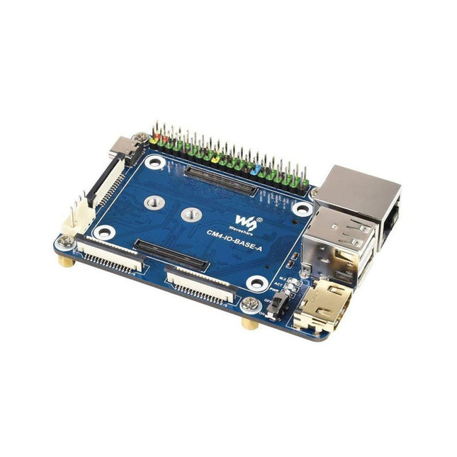
CM4 socket
Suitable for all variants of Compute Module 4
Networking
Gigabit Ethernet RJ45 connectorM.2 M KEY, supports communication modules or NVME SSD
Connector
Raspberry Pi 40-PIN GPIO header
USB
2x USB 2.0 Type A2x USB 2.0 via FFC connector
Display
MIPI DSI display port (15-pin 1.0 mm FPC connector)
Camera
2x MIPI CSI-2 camera port (15-pin 1.0 mm FPC connector)
Video
2x HDMI port (including one port via FFC connector), supports 4K 30fps output
RTC
N/A
Storage
MicroSD card socket for Compute Module 4 Lite (without eMMC) variants
Fan header
No fan control, 5 V
Power input
5 V
Dimensions
85 x 56 mm
Included
1x CM4-IO-BASE-A
1x SSD mounting screw
Downloads
Wiki
The Maker pHAT is the solution to the most common problems beginners face starting with Raspberry PI. Its intelligent and simple design makes it easy to attach to your Pi, and it helps you avoid all the tedious work of connection various other accessories. Additionally, the LEDs corresponding to each pin makes it extremely easy to see where a potential problem lies
The Maker pHat has the same size as the Raspberry Pi Zero with all 4mounting holes aligned. However, it can be used with Raspberry Pi 3B, 3B+ and 3A+, by inserting a 2 x 20 stacking header.
Features
Raspberry Pi Zero size, stack perfectly on to Raspberry Pi Zero
Compatible with standard size Raspberry Pi 3B / 3B+, medium size Raspberry Pi 3A+ and smaller size Raspberry Pi Zero / W / WH.
Standard Raspberry Pi GPIO footprint.
LED array for selected GPIO pins (GPIO 17, 18, 27, 22, 25, 12, 13, 19).
3x on board programmable push buttons (GPIO 21, 19 and 20, need to configure as input pull up).
Onboard active buzzer (GPIO 26).
Proper labels for all GPIOs, including SPI, UART, I2C, 5V, 3.3V, and GND.
Utilize USB Micro-B socket for 5V input and USB to UART communication.
USB serial facilitated by the FT231X
Input voltage: USB 5 V, from a computer, power bank or a standard USB adapter.
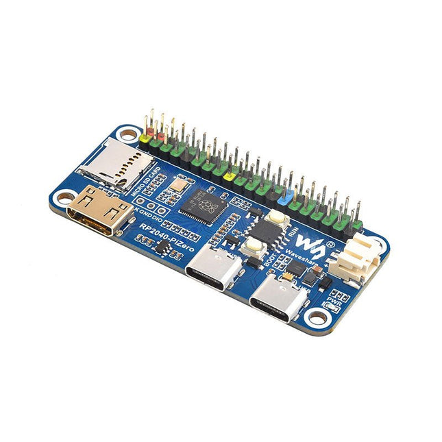
Waveshare RP2040-PiZero is a high-performance and cost-effective microcontroller board with onboard DVI interface, TF card slot and PIO-USB port, compatible with Raspberry Pi 40-pin GPIO header, easy to develop and integrate into the products.
Features
RP2040 microcontroller chip designed by Raspberry Pi
Dual-core ARM Cortex M0+ processor, flexible clock running up to 133 MHz
264 KB of SRAM, and 16 MB of onboard Flash memory
Onboard DVI interface can drive most HDMI screens (DVI compatibility required)
Supports using as a USB host or slave via onboard PIO-USB port
Onboard TF card slot for reading and writing TF card
Onboard Lithium battery recharge/discharge header, suitable for mobile scenarios
USB 1.1 with device and host support
Drag-and-drop programming using mass storage over USB
Low-power sleep and dormant modes
2x SPI, 2x I²C, 2x UART, 4x 12-bit ADC, 16x controllable PWM channels
Accurate clock and timer on-chip
Temperature sensor
Accelerated floating-point libraries on-chip
Downloads
Wiki
The SparkFun RedBoard Qwiic is an Arduino-compatible board that combines features of different Arduinos with the Qwiic Connect System.
Features
ATmega328 microcontroller with Optiboot Bootloader
R3 Shield Compatible
CH340C Serial-USB Converter
3.3 V to 5 V Voltage Level Jumper
A4 / A5 Jumpers
AP2112 Voltage Regulator
ISP Header
Input voltage: 7 V - 15 V
1 Qwiic Connector
16 MHz Clock Speed
32 k Flash Memory
All SMD Construction
Improved Reset Button
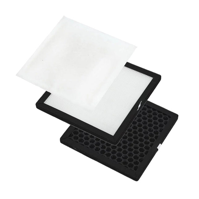
This complete replacement filter set for the Aoyue 8486 Fume Extractor contains a HEPA (High Efficiency Particulate Air) filter, a cotton air (sub) filter and an activated carbon air filter.
A modern USB-C connector makes programming easy. In addition to the pins broken out, two separate Qwiic-enabled I²C ports allow you to easily daisy chain Qwiic-enabled devices. We've exposed the SWD pins for more advanced users who prefer to use professional tools' power and speed. A USB-A connector is provided for Processor Boards that have USB Host support. A backup battery is provided for processor boards with RTC. If you need a 'lot' of GPIO with a simple-to-program, ready for the market module, the ATP is the fix you need. We've even added a convenient jumper to measure the current consumption for low power testing. Features M.2 Connector Operating Voltage Range ~3.3 V to 6.0 V (via VIN to AP7361C 3.3V Voltage Regulator) 3.3 V (via 3V3) Ports 1x USB type C 1x USB type A Host 2x Qwiic Enabled I²C 1x CAN 1x I²S 2x SPI 2x UARTs 2x Dedicated Analog Pins 2x Dedicated PWM Pins 2x Dedicated Digital Pins 12x General Purpose Input Output Pins 1x SWD 2x5 header 1 mAh battery backup for RTC Buttons Reset Boot LEDs Power 3.3 V Phillips #0 M2.5x3mm screw included
Features
Compatible with Raspberry Pi 4 only
Cutout in lid for 40x30mm heatsink or Fan SHIM
Super-slimline profile
Fully HAT-compatible
Protects your beloved Pi
Clear top and base leave Raspberry Pi 4 visible
GPIO cut-out
Handy laser-etched port labels
Leaves all ports accessible
Made from lightweight, high-quality, cast acrylic
Great for hacking and tinkering!
Made in Sheffield, UK
Weighing just over 50 grams, the case is lightweight and ideal for mounting to any surface. No tools are required for assembly or disassembly. The dimensions are: 99 × 66 × 15 mm.
In the video below you can see a quick assembly guide.
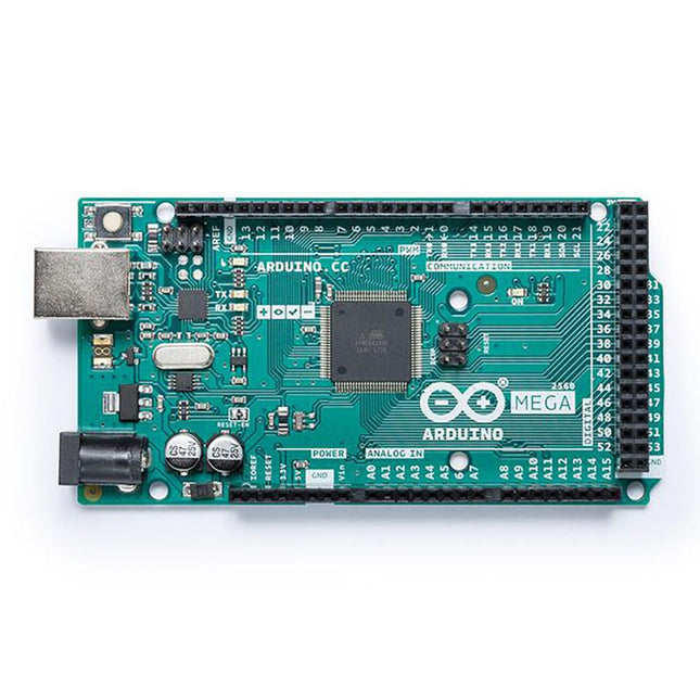
The Mega 2560 board is compatible with most shields designed for the Uno and the former boards Duemilanove or Diecimila.
Specifications
Operating Voltage
5 V
Input Voltage
7 V - 12 V
Digital I/O
54
Analog Input Pins
16
DC Current per I/O Pin
20 mA
DC Current for 3.3 V Pin
50 mA
Flash Memory
256 KB of which 8 KB used by the bootloader
SRAM
8 KB
EEPROM
4 KB
Clock Speed
16MHz
LED_Builtin
13
Length
101.52 mm
Width
53.3 mm
Weight
37 g
For more information, check out the Getting Started Guide from Arduino.
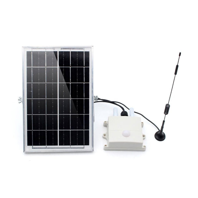
This air monitor is specifically used for monitoring greenhouses. It detects:
Air temperature & Humidity
CO2 concentration
Light intensity
Then transmit the data via LoRa P2P to the LoRa receiver (on your desk in the room) so that the user can monitor the field status or have it recorded for long-term analysis.
This module monitors the greenhouse field status and sends all sensor data regularly via LoRa P2P in Jason format. This LoRa signal can be received by the Makerfabs LoRa receiver and thus displayed/recorded/analyzed on the PC. The monitoring name/data cycle can be set with a phone, so it can be easily implemented into the file.
This air monitor is powered by an internal LiPo battery charged by a solar panel and can be used for at least 1 year with the default setting (cycle 1 hour).
Features
ESP32S3 module onboard with the WiFi and Bluetooth
Ready to use: Power it on directly to use
Module name/signal interval settable easily by phone
IP68 water-proof
Temperature: -40°C~80°C, ±0.3
Humidity: 0~100% moisture
CO2: 0~1000 ppm
Light intensity: 1-65535 lx
Communication distance: Lora: >3 km
1000 mAh battery, charger IC onboard
Solar panel 6 W, ensure system works
Downloads
Manual
BH1750 Datasheet
SGP30 Datasheet
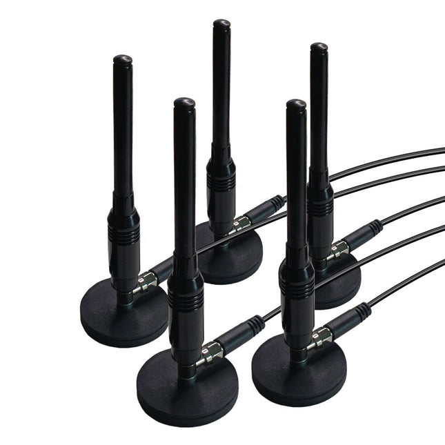
This is a set of five magnetic, telescopic whip antennas – with 100 MHz to 1 GHz tuning range – that can be used with KrakenSDR for direction finding. The magnets are strong and will be secure on the roof of a moving car. It includes a set of five two-meter, LMR100-equivalent coax cables that have been length matched for better performance.
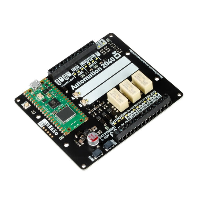
An all-in-one, Pico W powered industrial/automation controller with 2.46 GHz wireless connectivity, relays and a plethora of inputs and outputs. Compatible with 6 V to 40 V systems.
Automation 2040 W is a Pico W / RP2040 powered monitoring and automation board. It contains all the great features from the Automation HAT (relays, analog channels, powered outputs and buffered inputs) but now in a single compact board and with an extended voltage range so you can use it with more devices. Great for controlling fans, pumps, solenoids, chunky motors, electronic locks or static LED lighting (up to 40 V).
All the channels (and the buttons) have an associated indicator LED so you can see at a glance what's happening with your setup, or test your programs without having hardware connected.
Features
Raspberry Pi Pico W Aboard
Dual Arm Cortex M0+ running at up to 133 Mhz with 264 kB of SRAM
2 MB of QSPI flash supporting XiP
Powered and programmable by USB micro-B
2.4 GHz wireless
3x 12-bit ADC inputs up to 40 V
4x digital inputs up to 40 V
3x digital sourcing outputs at V+ (supply voltage)
4 A max continuous current
2 A max current at 500 Hz PWM
3x relays (NC and NO terminals)
2 A up to 24 V
1 A up to 40 V
3.5 mm screw terminals for connecting inputs, outputs and external power
2x tactile buttons with LED indicators
Reset button
2x Qw/ST connectors for attaching breakouts
M2.5 mounting holes
Fully assembled
No soldering required.
C/C++ and MicroPython libraries
Schematic
Dimensional drawing
Power
Board is compatible with 12 V, 24 V and 36 V systems
Requires supply 6-40 V
Can provide 5 V up to 0.5 A for lower voltage applications
Software
Pirate-brand MicroPython
Getting Started with Raspberry Pi Pico
MicroPython examples
MicroPython function reference
C++ examples
C++ function reference
Getting Started with Automation 2040 W
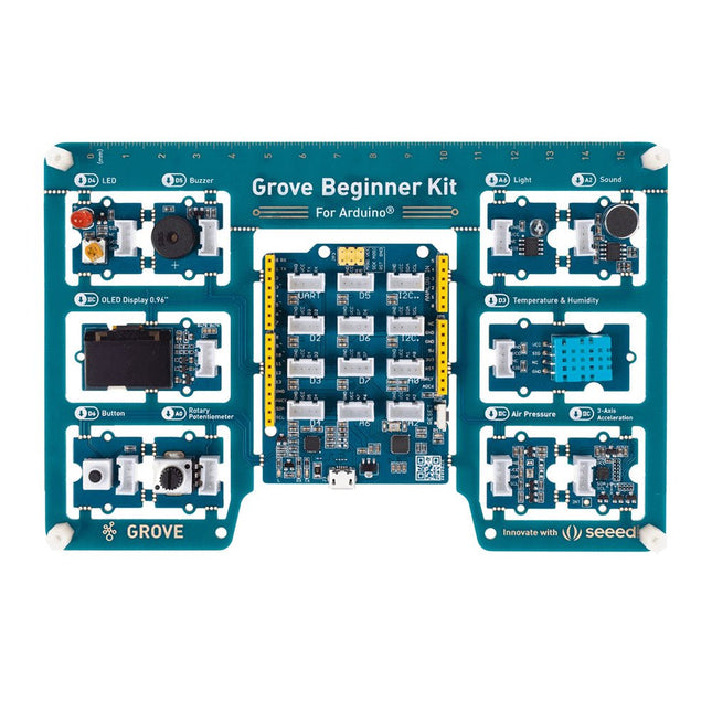
Unlike most kits, the Grove Beginner Kit for Arduino is an all-in-one kit, no breadboard, no soldering, even no wiring is needed. The kit is powered by one Arduino compatible Board (Seeeduino Lotus) together with 10 additional Grove Arduino sensors all in one piece of the board.
All the modules have been connected to the Seeeduino(Microcontroller) through the PCB stamp holes so no Grove cables are needed to connect. This is perfect for educational fields where frustrating wiring and soldering are no longer needed.
Of course, you can also take the modules out and use Grove cables to connect the modules. You can build any Arduino project you like with this Grove Beginner Kit For Arduino.
Included
1x Grove Beginner Kit For Arduino Board
1x Micro USB Cable
6x Grove Cables
Included onboard
1x Grove LED
1x Grove Buzzer
1x Grove OLED Display 0.96"
1x Grove Button
1x Grove Rotary Potentiometer
1x Grove Light
1x Grove Sound
1x Grove Temperature & Humidity Sensor
1x Grove Air Pressure Sensor
1x Grove 3-Axis Accelerator
1x Seeeduino Lotus
This rugged, passive aluminum cooling case is made specifically for the Raspberry Pi 5 and offers a sleek design that ensures both durability and effective heat dissipation. The case is exclusively compatible with the Raspberry Pi 5 and provides a passive cooling solution, eliminating the need for a fan while still managing heat efficiently.
Features
High quality aluminum construction: Made from high quality aluminum, this case is built to last and withstand regular use.
Optimized heat dissipation: The passive cooling design uses the aluminum structure to keep your Raspberry Pi 5 cool without the need for a fan.
Full port accessibility: Every port on the Raspberry Pi 5 is easily accessible, from the microSD card slot to USB, micro HDMI and GPIO ports.
GPIO cable support: A reserved interface for the GPIO cable ensures that you can continue to use this important function without having to remove the case.
Convenient power switch: The case has an integrated power switch that allows you to turn your device on and off.
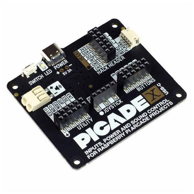
Turn your Raspberry Pi into a retro games console! Picade X HAT includes joystick and button inputs, a 3 W I²S DAC/amplifier, and soft power switch. This HAT has all the same great features as the original Picade HAT but now has no-fuss female Dupont connectors to hook up your joystick and buttons. Simply pop Picade X HAT onto your Pi, plug a USB-C power supply into the connector on the HAT (it back-powers your Pi through the GPIO, so no need for a separate power supply), wire up your controls, and install the driver! It's ideal for your own DIY arcade cabinet builds, or for interfaces that need big, colourful buttons and sound. Features I²S audio DAC with 3 W amplifier (mono) and push-fit terminals Safe power on/off system with tactile power button and LED USB-C connector for power (back-powers your Pi) 4-way digital joystick inputs 6x player button inputs 4x utility button inputs 1x soft power switch input 1x power LED output Plasma button connector Breakout pins for power, I²C, and 2 additional buttons Picade X HAT pinout Compatible with all 40-pin Raspberry Pi models The I²S DAC blends both channels of digital audio from the Raspberry Pi into a single mono output. This is then passed through a 3 W amplifier to power a connected speaker. The board also features a soft power switch that allows you turn your Pi on and off safely without risk of SD card corruption. Tap the connected button to start up, and press and hold it for 3 seconds to fully shutdown and disconnect power. Software/Installation Open a terminal and type curl https://get.pimoroni.com/picadehat | bash to run the installer. You'll need to reboot once the installation is complete, if it doesn't prompt you to do so. The software does not support Raspbian Wheezy Notes With USB-C power connected through Picade X HAT you'll need either to tap the connected power button or the button marked 'switch' on the HAT to power on your Pi.
Add colors to your projects with this collection of red, green, yellow, blue and white LEDs. They come with various current limiting resistors in order to protect the parts and control the brightness.Included
10 mm LEDs
1x red
1x green
1x yellow
1x blue
1x white
5 mm LEDs
5x red
5x green
5x yellow
5x blue
5x white
3 mm LEDs
5x red
5x green
5x yellow
5x blue
5x white
25x 330 Ω resistors
10x 1 kΩ resistors
10x 10 kΩ resistors
10x 100 kΩ resistors
10x 1 MΩ resistors
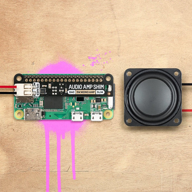
SHIM is an old Yorkshire term meaning 'Shove Hardware In Middle' - we use it for Raspberry Pi add-ons that are designed to be sandwiched between your Pi and a HAT or mini HAT. This one has a clever friction fit header that slips handily over your GPIO pins, doesn't need soldering*, and is easily removable.
The MAX98357A combined DAC / amplifier chip takes high-quality digital audio from your Pi and amplifies it so it can be used with an unpowered speaker. The push-fit connectors make it straightforward to connect up your speaker, whether it's a bookshelf or floor-standing speaker, the speaker in an old radio, or any other speaker you might have laying around.
Because Audio Amp SHIM adds no extra bulk to your Pi it's perfect for building into a compact enclosure - you could use it to make a tiny MP3 player to play local files or stream from services like Spotify, give a vintage radio the ability to play digital radio streams or incorporate bleepy noises into your very own retro handheld. It's also a handy way to add audio output to your Pi Zero or Pi 400!
Please note: Raspberry Pi and speakers are not included with this board.
Features
MAX98357A DAC / amplifier chip
Mono 3W audio out
Push-fit speaker terminals
SHIM-format board with friction-fit connectors
2x mounting holes (M2.5) for if you want to secure everything together with bolts
Fully-assembled
No soldering required (*unless you're using a Pi that comes without a header)
Compatible with all 40-pin header Raspberry Pi models
Software
The easiest way to get everything set up is to use Pimoroni's Pirate Audio software and installer which configures I2S audio, as well as installing Mopidy and our custom Pirate Audio plugins which will let you stream Spotify and play local files.
Here's how to get started:
Set an SD card up with the latest version of Raspberry Pi OS.
Connect to Wi-Fi or a wired network.
Open a terminal and type the following:git clone https://github.com/pimoroni/pirate-audiocd pirate-audio/mopidysudo ./install.sh
Reboot your Pi
Downloads
MAX98357A Datasheet
Pirate Audio software
Schematic
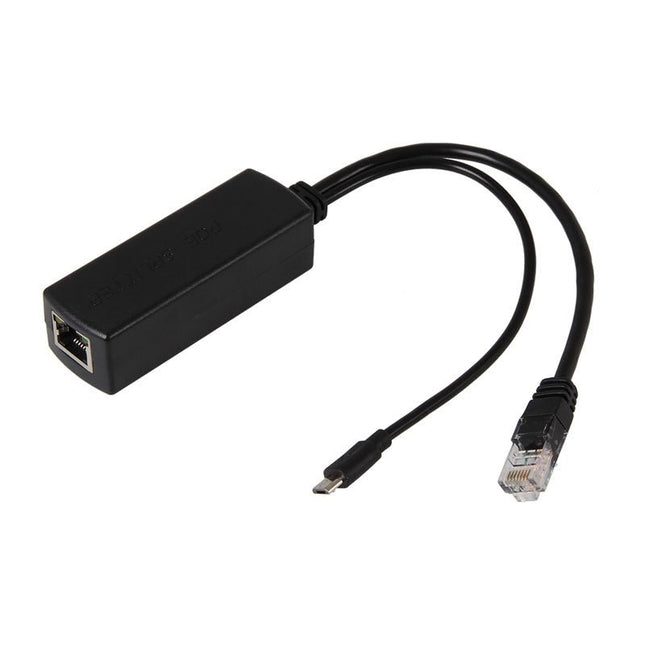
Features
Jack: 1x Micro USB power plug + 1x RJ45 output port
Input Voltage: 36~57 V (standard PoE voltage 48 V, 52 V)
Output Voltage: DC 5 V
Output Current: 2 A
Transmission Distance: 10~100 m
PoE Protocol: IEEE802.3af
Network Bandwidth: 10/100 Mbps
Weight: 40 g
Product Dimension: 82 x 28 x 23 mm
Cable Length: 205 mm
Operation Temperature: -50 °C up to +75 °C