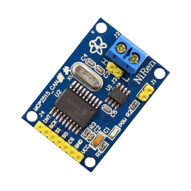
This CAN Module is based on the CAN bus controller MCP2515 and CAN transceiver TJA1050. With this module, you will easy to control any CAN Bus device by SPI interface with your MCU, such as Arduino Uno and so on. Features Support CAN V2.0B Communication rate up to 1 MB/s Working Voltage: 5 V Working Current: 5 mA Interface: SPI Downloads MCP2515 Datasheet TJA1050 Datasheet
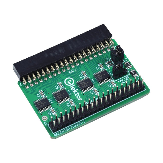
When you experiment with the Raspberry Pi on a regular basis and you connect a variety of external hardware to the GPIO port via the header you may well have caused some damage in the past. The Elektor Raspberry Pi Buffer Board is there to prevent this! The board is compatible with Raspberry Pi Zero, Zero 2 (W), 3, 4, 5, 400 and 500.
All 26 GPIOs are buffered with bi-directional voltage translators to protect the Raspberry Pi when experimenting with new circuits. The PCB is intended to be inserted in the back of Raspberry Pi 400/500. The connector to connect to the Raspberry Pi is a right angled 40-way receptacle (2x20). The PCB is only a fraction wider. A 40-way flat cable with appropriate 2x20 headers can be connected to the buffer output header to experiment for instance with a circuit on a breadboard or PCB.
The circuit uses 4x TXS0108E ICs by Texas Instruments. The PCB can also be put upright on a Raspberry Pi.
Downloads
Schematics
Layout
The Zero Delay Encoder Encoder makes it simple to attach your own arcade joysticks and buttons, and to connect to the Raspberry, PC or other devices. Create your own controller and enjoy your games without any compromises or control your robot project according to your ideas. Features Compatible with Linux, Windows, MAME and other common emulators and systems. Complete controller base with all cables included Supports up to 12 buttons Auto, Fire and Turbo modes Additional connection: Sanwa/Seimitsu 5-Pin LEDs: 1 × Power-LED, 1 × Mode-LED The scope of delivery includes Zero Delay Encoder, USB Cable, 13 × 4.8 mm cable.
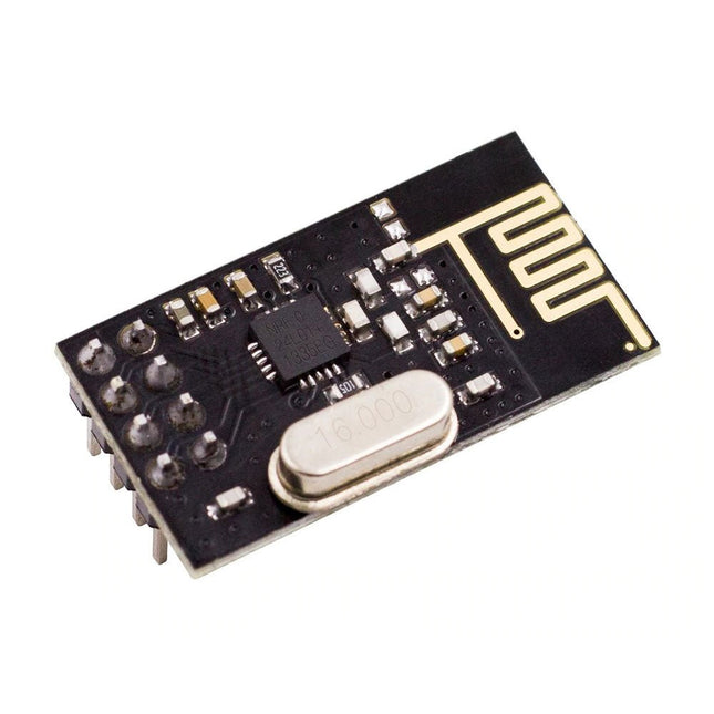
NRF24L01 is a universal ISM band monolithic transceiver chip works in the 2.4-2.5 GHz. Features Wireless transceiver including: Frequency generator, enhanced type, SchockBurstTM, mode controller, power amplifier, crystal amplifier, modulator, demodulator The output power channel selection and protocol settings can be set extremely low current consumption, through the SPI interface As the transmit mode, the transmit power is 6 dBm, the current is 9.0 mA, the accepted mode current is 12.3 mA, the current consumption of the power-down mode and standby mode are lower Built-in 2.4 GHz antenna, supports up to six channels of data reception Size: 15 x 29 mm (including antenna)
Based on the SparkFun GPS-RTK2 designs, the SparkFun GPS-RTK-SMA raises the bar for high-precision GPS and is the latest in a line of powerful RTK boards featuring the ZED-F9P module from u-blox. The ZED-F9P is a top-of-the-line module for high accuracy GNSS and GPS location solutions, including RTK capable of 10mm, three-dimensional accuracy. With this board, you will be able to know where your (or any object's) X, Y, and Z location is within roughly the width of your fingernail! The ZED-F9P is unique in that it is capable of both rover and base station operations. Utilizing our handy Qwiic system, no soldering is required to connect it to the rest of your system. However, we still have broken out 0.1"-spaced pins if you prefer to use a breadboard.
We've included a rechargeable backup battery to keep the latest module configuration and satellite data available for up to two weeks. This battery helps 'warm start' the module decreasing the time-to-first-fix dramatically. This module features a survey-in mode allowing the module to become a base station and produce RTCM 3.x correction data. Based on your feedback, we switched out the u.FL connector and included an SMA connector in this version of the board.
The number of configuration options of the ZED-F9P is incredible! Geofencing, variable I²C address, variable update rates, even the high precision RTK solution can be increased to 20Hz. The GPS-RTK2 even has five communications ports which are all active simultaneously: USB-C (which enumerates as a COM port), UART1 (with 3.3V TTL), UART2 for RTCM reception (with 3.3V TTL), I²C (via the two Qwiic connectors or broken out pins), and SPI.
SparkFun has also written an extensive Arduino library for u-blox modules to easily read and control the GPS-RTK-SMA over our Qwiic Connect System. Leave NMEA behind! Start using a much lighter weight binary interface and give your microcontroller (and its one serial port) a break. The SparkFun Arduino library shows how to read latitude, longitude, even heading and speed over I²C without the need for constant serial polling.
Features
Concurrent reception of GPS, GLONASS, Galileo and BeiDou
Receives both L1C/A and L2C bands
Voltage: 5 V or 3.3 V, but all logic is 3.3 V
Current: 68 mA - 130 mA (varies with constellations and tracking state)
Time to First Fix: 25 s (cold), 2 s (hot)
Max Navigation Rate:
PVT (basic location over UBX binary protocol) - 25 Hz
RTK - 20 Hz
Raw - 25 Hz
Horizontal Position Accuracy:
2.5 m without RTK
0.010 m with RTK
Max Altitude: 50 km
Max Velocity: 500 m/s
Weight: 6.8 g
Dimensions: 43.5 mm x 43.2 mm
2 x Qwiic Connectors
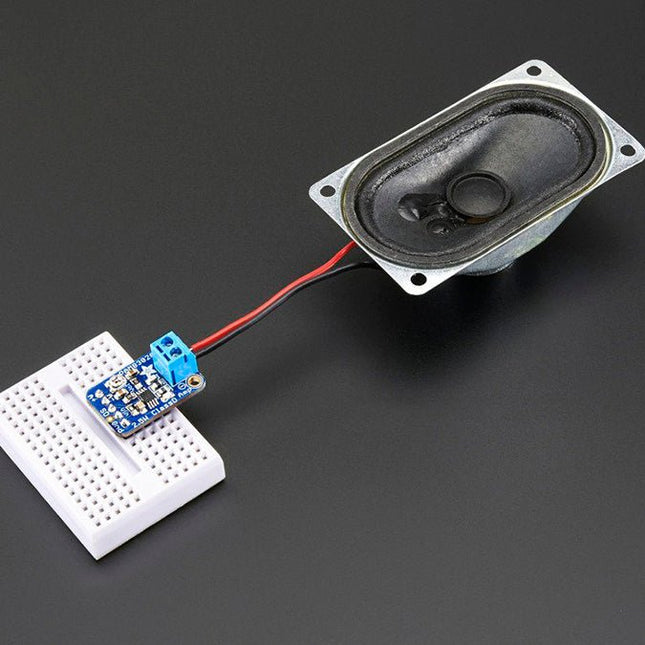
This small mono amplifier is surprisingly powerful – able to deliver up to 2.5 W into 4-8 Ω impedance speakers. Inside the miniature chip is a class D controller, able to run from 2.0-5.5 V DC. Since the amplifier is a class D, it's very efficient making it perfect for portable and battery-powered projects. It has built-in thermal and over-current protection. There's even a volume trim pot so you can adjust the volume on the board down from the default 24 dB gain.
The A+ and A- inputs of the amplifier go through 1.0 µF capacitors, so they are fully 'differential' – if you don't have differential outputs, simply tie the Audio-pin to ground. The output is 'Bridge Tied' – that means the output pins connect directly to the speaker pins, no connection to ground. The output is a high frequency 250 KHz square wave PWM that is then 'averaged out' by the speaker coil – the high frequencies are not heard. All the above means that you can't connect the output into another amplifier, it should drive the speakers directly.
The amplifier comes with a fully assembled and tested breakout board, a header to plug it into a breadboard and a 3.5 mm screw-terminal blocks so you can easily attach/detach your speaker. Speaker is not included, we recommend using any 4 Ω or greater impedance speaker.
Features
Output Power: 2.5 W at 4 Ω, 10% THD (total harmonic distortion), 1.5 W at 8 Ω, 10% THD, with 5.5 V Supply
50 dB PSRR (power supply rejection ratio) at 1 KHz
Filterless design, with ferrite bead + capacitors on output.
Fixed 24 dB gain, an onboard trim potentiometer for adjusting input volume.
Thermal and short-circuit/over-current protection
Low current draw: 4 mA quiescent and 0.5 mA in shutdown (due to pull-up resistor on SD pin)
A modern USB-C connector makes programming easy. In addition to the pins broken out, two separate Qwiic-enabled I²C ports allow you to easily daisy chain Qwiic-enabled devices. We've exposed the SWD pins for more advanced users who prefer to use professional tools' power and speed. A USB-A connector is provided for Processor Boards that have USB Host support. A backup battery is provided for processor boards with RTC. If you need a 'lot' of GPIO with a simple-to-program, ready for the market module, the ATP is the fix you need. We've even added a convenient jumper to measure the current consumption for low power testing. Features M.2 Connector Operating Voltage Range ~3.3 V to 6.0 V (via VIN to AP7361C 3.3V Voltage Regulator) 3.3 V (via 3V3) Ports 1x USB type C 1x USB type A Host 2x Qwiic Enabled I²C 1x CAN 1x I²S 2x SPI 2x UARTs 2x Dedicated Analog Pins 2x Dedicated PWM Pins 2x Dedicated Digital Pins 12x General Purpose Input Output Pins 1x SWD 2x5 header 1 mAh battery backup for RTC Buttons Reset Boot LEDs Power 3.3 V Phillips #0 M2.5x3mm screw included
The board provides you with an economical and easy to use development platform if you're needing more power with minimal working space. With the M.2 MicroMod connector, connecting your SAMD51 Processor is a breeze. Simply match up the key on your processor's bevelled edge connector to the key on the M.2 connector and secure it with a screw (included with all Carrier Boards). The SAMD51 is one of the most powerful and economical microcontrollers available so to be able to add it to your MicroMod Carrier Board is a huge advantage for your project!
The ATSAMD51J20 utilizes a 32-bit ARM Cortex-M4 processor with Floating Point Unit (FPU), running up to 120MHz, up to 1MB of flash memory, up to 256KB of SRAM with ECC, up to 6 SERCOM interfaces, and other features. This MicroMod SAMD51 even comes flashed with the same convenient UF2 bootloader as the SAMD51 Thing Plus and the RedBoard Turbo.
Features
ATSAMD51J20 microcontroller
32-bit ARM Cortex-M4F MCU
Up to 120 MHz CPU speed
1 MB flash memory
256 KB SRAM
Up to 6 SERCOM interfaces
UF2 bootloader
1x USB dedicated for programming and debug (Host capable)
2x UARTs
2x I²C
1x SPI
1x CAN
11x GPIO
2x Digital Pins
2x Analog Pins
2x PWM
128 mbit / 16 MB (external) flash memory
Status LED
VIN Level ADC
The SparkFun Qwiic OpenLog is the smarter and better looking cousin to the extremely popular OpenLog but now we've ported the original serial based interface to I²C! Thanks to the added Qwiic connectors, you can daisy chain multiple I²C devices and log them all without taking up your serial port. The Qwiic OpenLog can store, or 'log', huge amounts of serial data and act as a black box of sorts to store all the data that your project generates, for scientific or debugging purposes. Utilizing our handy Qwiic system, no soldering is required to connect it to the rest of your system. However, we still have broken out 0.1'-spaced pins in case you prefer to use a breadboard. Like its predecessor, the SparkFun Qwiic OpenLog runs off of an onboard ATmega328, running at 16 MHz thanks to the onboard resonator. The ATmega328 has been sure to feature the Optiboot bootloader loaded, which allows the OpenLog to be compatible with the “Arduino Uno” board setting in the Arduino IDE. It is important to be aware that the Qwiic OpenLog draws approximately 2 mA-6 mA in idle (nothing to record) mode, however, during a full record the OpenLog can draw 20 mA to 23 mA depending on the microSD card being used. The Qwiic OpenLog also supports clock stretching, which means it performs even better than the original and will record data up to 20,000 bytes per second at 400 kHz. As the receive buffer fills up this OpenLog will hold the clock line, letting the master know that it is busy. Once the Qwiic OpenLog is finished with a task, it releases the clock thus allowing the data to continue flowing without corruption. For even better performance the OpenLog Artemis is the tool you need, featuring logging speeds up to 500000 bps. Features Continuous data logging at 20,000 bytes per second without corruption Compatible with high speed 400 kHz I²C Compatible with 64 MB to 32 GB microSD cards (FAT16 or FAT32) Preloaded Uno bootloader so upgrading the firmware is as easy as loading a new sketch Valid I²C Addresses: 0x08 to 0x77 2x Qwiic Connectors Downloads Schematic Eagle Files Hookup Guide Arduino Library GitHub
The Data Logging Carrier Board breaks out connections for I²C via a Qwiic connector or standard 0.1'-spaced PTH pins along with SPI and serial UART connections for logging data from peripheral devices using those communication protocols.
The Data Logging Carrier Board allows you to control power to both the Qwiic connector on the board and a dedicated 3.3 V power rail for non-Qwiic peripherals so you can pick and choose when to power the peripherals you are monitoring the data from. It also features a charging circuit for single-cell Lithium-ion batteries along with a separate RTC battery-backup circuit to maintain power to a real-time clock circuit on your Processor Board.
Features
M.2 MicroMod Connector
microSD socket
USB-C Connector
3.3 V 1 A Voltage Regulator
Qwiic Connector
Boot/Reset Buttons
RTC Backup Battery & Charge Circuit
Independent 3.3 V regulators for Qwiic bus and peripheral add-ons
Controlled by digital pins on Processor Board to enable low power sleep modes
Phillips #0 M2.5 x 3 mm screw included
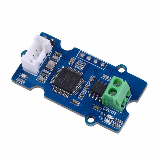
This Grove CAN-BUS Module based on GD32E103 adopts a brand-new design, uses the cost-effective and high-performance GD32E103 microcontroller as the main control and cooperates with a firmware we wrote to complete the function of the serial port to CAN FD. Features
Support CAN communication: Implements CAN FD at up to 5 Mb/s
Easy to program: Support AT command which enables simple serial port programming
Grove ecosystem: 20 x 40 x 10 mm small size, 4-pin Grove connector to plug and play, Arduino compatible This Grove CAN-BUS Module supports CAN FD(CAN with Flexible Data-Rate) communication, which is an extension to the original CAN protocol as specified in ISO 11898-1 that responds to increased bandwidth requirements in automotive networks. In CAN FD, the data rate (i.e. number of bits transmitted per second) is increased to be 5 times faster than the classic CAN (5 Mbit/s for the data payload only, the arbitration bit rate is still limited to 1Mbit/s for compatibility). It supports AT command which enables simple serial port programming. This Grove CAN-BUS Module is based on GD32E103 with a frequency up to 120 MHz. It has a flash size from 64 KB to 128 KB and an SRAM size from 20 KB to 32 KB. Applications Car hacking: allows different parts of the vehicle to talk to each other, including the engine, the transmission, and the brakes. Windows, doors, and mirror adjustment. 3D Printers Building automation Lighting control systems Medical instruments and equipment Specifications MCU GD32E103 UART baud rate Up to 115200 (default 9600) CAN FD baud rate Up to 5 Mb/s Indicator TX and RX led Working voltage 3.3 V Grove connector 4-pin Grove connector to plug and play Size 20 x 40 x 10 mm Downloads Datasheet GitHub
This module includes an integrated trace antenna, fits the IC to an FCC-approved footprint, and includes decoupling and timing mechanisms that would need to be designed into a circuit using the bare nRF52840 IC. The Bluetooth transceiver included on the nRF52840 boasts a BT 5.1 stack. It supports Bluetooth 5, Bluetooth mesh, IEEE 802.15.4 (Zigbee & Thread) and 2.4Ghz RF wireless protocols (including Nordic's proprietary RF protocol) allowing you to pick which option works best for your application.
Features
ARM Cortex-M4 CPU with a floating-point unit (FPU)
1MB internal Flash -- For all of your program, SoftDevice, and file-storage needs!
256kB internal RAM -- For your stack and heap storage.
Integrated 2.4GHz radio with support for:
Bluetooth Low Energy (BLE) -- With peripheral and/or central BLE device support
Bluetooth 5 -- Mesh Bluetooth!
ANT -- If you want to turn the device into a heart-rate or exercise monitor.
Nordic's proprietary RF protocol -- If you want to communicate, securely, with other Nordic devices.
Every I/O peripheral you could need.
USB -- Turn your nRF52840 into a USB mass-storage device, use a CDC (USB serial) interface, and more.
UART -- Serial interfaces with support for hardware flow-control if desired.
I²C -- Everyone's favourite 2-wire bi-directional bus interface
SPI -- If you prefer the 3+-wire serial interface
Analogue-to-digital converters (ADC) -- Eight pins on the nRF52840 Mini Breakout support analogue inputs
PWM -- Timer support on any pin means PWM support for driving LEDs or servo motors.
Real-time clock (RTC) -- Keep close track of seconds and milliseconds, also supports timed deep-sleep features.
Three UARTs
Primary tied to USB interface. Two hardware UARTs.
Two I²C Buses
Two SPI Buses
Secondary SPI Bus primarily used for Flash IC.
PDM Audio Processing
Two Analog Inputs
Two Dedicated Digital I/O Pins
Two Dedicated PWM Pins
Eleven General Purpose I/O Pins
Voice recognition, always-on voice commands, gesture, or image recognition are possible with TensorFlow applications. The cloud is impressively robust, but all-the-time connection requires power and connectivity that may not be available. Edge computing handles discrete tasks such as determining if someone said 'yes' and responds accordingly. The audio analysis is done on the MicroMod combination rather than on the web. This dramatically reduces costs and complexity while limiting potential data privacy leaks.
This board features two MEMS microphones (one with a PDM interface, one with an I²S interface), an ST LIS2DH12 3-axis accelerometer, a connector to interface to a camera (sold separately), and a Qwiic connector. A modern USB-C connector makes programming easy and we've exposed the JTAG connector for more advanced users who prefer to use the power and speed of professional tools. We've even added a convenient jumper to measure current consumption for low power testing.
Features
M.2 MicroMod Keyed-E H4.2mm 65 pins SMD Connector 0.5mm
Digital I²C MEMS Microphone PDM Invensense ICS-43434 (COMP)
Digital PDM MEMS Microphone PDM Knowles SPH0641LM4H-1 (IC)
ML414H-IV01E Lithium Battery for RTC
ST LIS2DH12TR Accelerometer (3-axis, ultra-low-power)
24 Pin 0.5mm FPC Connector (Himax camera connector)
USB-C
Qwiic connector
MicroSD socket
Phillips #0 M2.5x3mm screw included
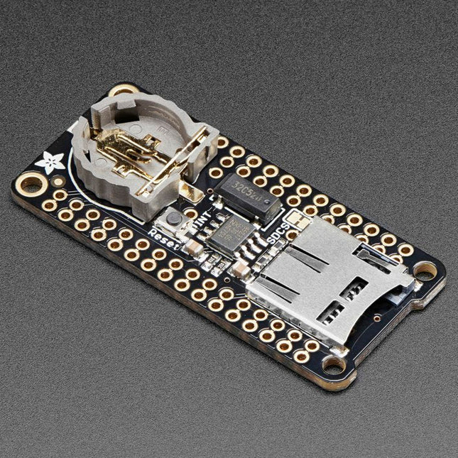
This FeatherWing will make it easy to add data logging to any Feather Board you might have. You get both an I²C real-time clock (PCF8523) with 32 KHz crystal and battery backup, and a microSD socket that connects to the SPI port pins (+ extra pin for CS). Note: FeatherWing doesn't come with a microSD card. A CR1220 coin cell is required to use the RTC battery-backup capabilities. If you're not using the RTC part of the FeatherWing, a battery is not required. To talk to the microSD card socket Arduino's default SD library is recommended. Some light soldering is required to attach the headers onto the Wing. Pinouts Power pins On the bottom row, the 3.3 V (second from left) and GND (fourth from left) pin are used to power the SD card and RTC (to take a load off the coin cell battery when main power is available) RTC & I²C Pins In the top right, SDA (rightmost) and SCL (to the left of SDA) are used to talk to the RTC chip.
SCL - I²C clock pin to connect to your microcontroller's I2C clock line. This pin has a 10 kΩ pull-up resistor to 3.3 V
SDA - I²C data pin to connect to your microcontroller's I2C data line. This pin has a 10 kΩ pull-up resistor to 3.3 V There's also a breakout for INT which is the output pin from the RTC. It can be used as an interrupt output or it could also be used to generate a square wave. Note that this pin is an open drain - you must enable the internal pull-up on whatever digital pin it is connected to. SD & SPI Pins Starting from the left you've got SPI Clock (SCK) - output from feather to wing SPI Master Out Slave In (MOSI) - output from feather to wing SPI Master In Slave Out (MISO) - input from wing to feather These pins are in the same location on every Feather. They are used for communicating with the SD card. When the SD card is not inserted, these pins are completely free. MISO is tri-stated whenever the SD CS (chip select) pin is pulled high
This carrier board combines a 2.4" TFT display, six addressable LEDs, onboard voltage regulator, a 6-pin IO connector, and microSD slot with the M.2 pin connector slot so that it can be used with compatible processor boards in our MicroMod ecosystem. We've also populated this carrier board with Atmel's ATtiny84 with 8kb of programmable flash. This little guy is preprogrammed to communicate with the processor over I²C to read button presses.
Features
M.2 MicroMod Connector
240 x 320 pixel, 2.4" TFT display
6 Addressable APA102 LEDs
Magnetic Buzzer
USB-C Connector
3.3 V 1 A Voltage Regulator
Qwiic Connector
Boot/Reset Buttons
RTC Backup Battery & Charge Circuit
microSD
Phillips #0 M2.5 x 3 mm screw included
The VL53L1X from STMicroelectronics uses a VCSEL (Vertical Cavity Surface Emitting Laser) to emit an Infrared laser to time the reflection to the target. That means that you will be able to measure the distance to an object from 40mm to 4m away with millimeter resolution! To make it even easier to get your readings, all communication is enacted exclusively via I²C, utilizing our handy Qwiic system, so no soldering is required to connect it to the rest of your system. However, we still have broken out 0.1”-spaced pins in case you prefer to use a breadboard. Each VL53L1X sensor features a precision to be 1mm with an accuracy around +/-5mm, and a minimum read distance of this sensor is 4cm. The field of view for this little breakout is fairly narrow at 15°-27° with a read rate of up to 50Hz. Make sure to power this board appropriately since it will need 2.6V-3.5V to operate. Lastly, please be sure to remove the protective sticker on the VL53L1X before use otherwise it will, most assuredly, throw off your readings. Features Operating Voltage: 2.6V-3.5V Power Consumption: 20 mW @10Hz Measurement Range: ~40mm to 4,000mm Resolution: +/-1mm Light Source: Class 1 940nm VCSEL 7-bit unshifted I²C Address: 0x29 Field of View: 15° - 27° Max Read Rate: 50Hz
This version of the Micro OLED Breakout is exactly the size of its non-Qwiic sibling, featuring a screen that is 64 pixels wide and 48 pixels tall and measuring 0.66' across. But it has also been equipped with two Qwiic connectors, making it ideal for I²C operations. We've also added two mounting holes and a convenient Qwiic cable holder incorporated into a detachable tab on the board that can be easily removed thanks to a v-scored edge. We've even made sure to include an I²C pull-up jumper and ADDR jumper on the back of the board, so if you have your own I²C pull-ups or need to change the I2C address of the board! Features Qwiic-Connector Enabled Operating Voltage: 3.3V Operating Current: 10mA (20mA max) Screen Size: 64x48 pixels (0.66' Across) Monochrome Blue-on-Black I²C Interface
The Qwiic Mux also has eight configurable addresses of its own, allowing for up to 64 I²C buses on a connection. To make it even easier to use this multiplexer, all communication is enacted exclusively via I²C, utilizing our handy Qwiic system. The Qwiic Mux also allows you to change the last three bits of the address byte, allowing for eight jumper selectable addresses if you happen to need to put more than one Qwiic Mux Breakout on the same I²C port. The address can be changed by adding solder to any of the three ADR jumpers. Each SparkFun Qwiic Mux Breakout operates between 1.65 V and 5.5 V, making it ideal for all of the Qwiic boards we produce in house.
The Sparkfun Qwiic GPIO is an I²C device based around the TCA9534 I/O Expander IC from Texas Instruments. The board adds eight IO pins that you can read and write just like any other digital pin on your controller. The details of the I²C interface have been taken care of in an Arduino library so you can call functions similar to Arduino's pinMode and digitalWrite, allowing you to focus on your creation! The TCA9534's pins are broken out to easy-to-use latch terminals; never screw another wire into place! The terminals are relatively roomy themselves, so feel free to latch multiple wires into a ground or power terminal. With three customizable address jumpers, you can have up to eight Qwiic GPIO boards connected on a single bus allowing upwards of 64 additional GPIO pins! The default I²C is 0x27 and can be changed by adjusting the jumpers on the board's back. Features Eight Configurable GPIO Pins Available I²C Address: 0x27 (Default) Hardware address pins allow up to eight boards on a single bus Input Polarity Inversion Register Control each I/O pin individually or all at once Open-Drain Active-Low Interrupt Output 2x Qwiic Connectors Dimensions: 60.96 x 38.10 mm
To make it even easier to use this breakout, all communication is enacted exclusively via I²C, utilizing our handy Qwiic system. However, we still have broken out 0.1' spaced pins in case you prefer to use a breadboard.
The CCS811 is an exceedingly popular sensor, providing readings for equivalent CO2 (or eCO2) in the parts per million (PPM) and total volatile organic compounds in the parts per billion (PPB). The CCS811 also has a feature that allows it to fine-tune its readings if it has access to the current humidity and temperature.
Luckily, the BME280 provides humidity, temperature and barometric pressure! This allows the sensors to work together to give us more accurate readings than they’d be able to provide on their own. We also made it easy to interface with them via I²C.
Features
Qwiic-Connector Enabled
Operation Voltage: 3.3 V
Total Volatile Organic Compound (TVOC) sensing from 0 to 1,187 parts per billion
eCO2 sensing from 400 to 8,192 parts per million
Temp Range: −40°C to +85°C
Humidity Range: 0-100% RH, = -3% from 20-80%
Pressure Range: 30,000Pa to 110,000Pa, relative accuracy of 12Pa, absolute accuracy of 100Pa
Altitude Range: 0 to 30,000 feet (9.2 km), relative accuracy of 3.3 feet (1 m) at sea level, 6.6 (2 m) at 30,000 feet
The SparkFun DataLogger IoT (9DoF) is a data logger that comes preprogrammed to automatically log IMU, GPS, and various pressure, humidity, and distance sensors. All without writing a single line of code! The DataLogger automatically detects, configures, and logs Qwiic sensors. It was specifically designed for users who just need to capture a lot of data to a CSV or JSON file and get back to their larger project. Save the data to a microSD card or send it wirelessly to your preferred Internet of Things (IoT) service!
Included on every DataLogger IoT is an IMU for built-in logging of a triple-axis accelerometer, gyro, and magnetometer. Whereas the original 9DOF Razor used the old MPU-9250, the DataLogger IoT uses the ISM330DHCX from STMicroelectronics and MMC5983MA from MEMSIC. Simply power up the DataLogger IoT, configure the board to record readings from supported devices, and begin logging! Data can be time-stamped when the time is synced to NTP, GNSS, or RTC.
The DataLogger IoT is highly configurable over an easy-to-use serial interface. Simply plug in a USB-C cable and open a serial terminal at 115200 baud. The logging output is automatically streamed to both the terminal and the microSD card. Pressing any key in the terminal window will open the configuration menu.
The DataLogger IoT (9DoF) automatically scans, detects, configures, and logs various Qwiic sensors plugged into the board (no soldering, no programming!).
Specifications
ESP32-WROOM-32E Module
Integrated 802.11b/g/n WiFi 2.4 GHz transceiver
Configurable via CH340C
Operating voltage range
3.3 V to 6.0 V (via VIN)
5 V with USB (via 5 V or USB type C)
3.6 V to 4.2 V with LiPo battery (via BATT or 2-pin JST)
Built-in MCP73831 single cell LiPo charger
Minimum 500 mA charge rate
3.3 V (via 3V3)
MAX17048 LiPo Fuel Gauge
Ports
1x USB-C
1x JST style connector for LiPo battery
2x Qwiic enabled I²C
1x microSD socket
Support for 4-bit SDIO and microSD cards formatted to FAT32
9-axis IMU
Accelerometer & Gyro (ISM330DHCX)
Magnetometer (MMC5983MA)
LEDs
Charge (CHG)
Status (STAT)
WS2812-2020 Addressable RGB
Jumpers
IMU interrupt
Magnetometer interrupt
RGB LED
Status LED
Charge LED
I²C pull-up resistors
USB Shield
Buttons
Reset
Boot
Dimensions: 1.66 x 2.0' (4.2 x 5.1 cm)
Weight: 10.7 g
Downloads
Schematic
Eagle Files
Board Dimensions
Hookup Guide
CH340 Drivers
Firmware
GitHub Hardware Repo
The Power Delivery Board uses a standalone controller to negotiate with the power adapters and switch to a higher voltage other than just 5V. This uses the same power adapter for different projects rather than relying on multiple power adapters to provide different output; it can deliver the board as part of SparkFun’s Qwiic connect system, so you won’t have to do any soldering to figure out how things are oriented.
The SparkFun Power Delivery Board takes advantage of the power delivery standard using a standalone controller from STMicroelectronics, the STUSB4500. The STUSB4500 is a USB power delivery controller that addresses sink devices. It implements a proprietary algorithm to negotiate a power delivery contract with a source (i.e. a power delivery wall wart or power adapter) without the need for an external microcontroller. However, you will need a microcontroller to configure the board. PDO profiles are configured in an integrated non-volatile memory. The controller does all the heavy lifting of power negotiation and provides an easy way to configure over I²C.
To configure the board, you will need an I²C bus. The Qwiic system makes it easy to connect the Power Delivery board to a microcontroller. Depending on your application, you can also connect to the I²C bus via the plated through SDA and SCL holes.
Features
Input and output voltage range of 5-20V
Output current up to 5A
Three configurable power delivery profiles
Auto-run Type-C™ and USB PD sink controller
Certified USB Type-C™ rev 1.2 and USB PD rev 2.0 (TID #1000133)
Integrated VBUS voltage monitoring
Integrated VBUS switch gate drivers (PMOS)
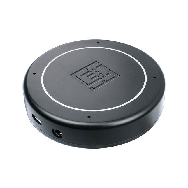
Features Plug & Play (No driver required), compatible with Windows 10/8/7, Mac, Linux and Android that support OTG. Voice Pick-up device, Far-field voice pick-up up to 5m and supports 360° pick-up pattern Acoustic algorithms implemented: DOA(Direction of Arrival), AEC(Automatic Echo Cancellation), AGC(Automatic Gain Control), NS(Noise Suppression) Built-in audio jack, which allows for plugging in headphones or speakers (speaker not included) Applications Voice pick-up device Home/Office automation device In-car voice assistant Healthcare device Voice interaction robot Other applications Technical Specifications XVF-3000 from XMOS 4 High-Performance Digital Microphones Supports Far-field Voice Capture Speech Algorithms On-Chip 12 Programmable RGB LED Indicators Microphones: MEMS MSM261D4030H1CPM Sensitivity: -26 dBFS (Omnidirectional) Acoustic Overload Point: 120 dB SPL SNR: 63 dB Power Supply: 5V DC from Micro USB or Expansion Header Dimensions: 77mm (Diameter) 3.5mm Audio Jack Output Socket
The SparkFun Thing Plus Matter is the first easily accessible board of its kind that combines Matter and SparkFun’s Qwiic ecosystem for agile development and prototyping of Matter-based IoT devices. The MGM240P wireless module from Silicon Labs provides secure connectivity for both 802.15.4 with Mesh communication (Thread) and Bluetooth Low Energy 5.3 protocols. The module comes ready for integration into Silicon Labs' Matter IoT protocol for home automation.
What is Matter? Simply put, Matter allows for consistent operation between smart home devices and IoT platforms without an Internet connection, even from different providers. In doing so, Matter is able to communicate between major IoT ecosystems in order to create a single wireless protocol that is easy, reliable, and secure to use.
The Thing Plus Matter (MGM240P) includes Qwiic and LiPo battery connectors, and multiple GPIO pins capable of complete multiplexing through software. The board also features the MCP73831 single-cell LiPo charger as well as the MAX17048 fuel gauge to charge and monitor a connected battery. Lastly, a µSD card slot for any external memory needs is integrated.
The MGM240P wireless module is built around the EFR32MG24 Wireless SoC with a 32-bit ARM Cortext-M33 core processor running at 39 MHz with 1536 kb Flash memory and 256 kb RAM. The MGM240P works with common 802.15.4 wireless protocols (Matter, ZigBee, and OpenThread) as well as Bluetooth Low Energy 5.3. The MGM240P supports Silicon Labs' Secure Vault for Thread applications.
Specifications
MGM240P Wireless Module
Built around the EFR32MG24 Wireless SoC
32-bit ARM-M33 Core Processor (@ 39 MHz)
1536 kB Flash Memory
256 kB RAM
Supports Multiple 802.15.4 Wireless Protocols (ZigBee and OpenThread)
Bluetooth Low Energy 5.3
Matter-ready
Secure Vault Support
Built-in Antenna
Thing Plus Form-Factor (Feather-compatible):
Dimensions: 5.8 x 2.3 cm (2.30 x 0.9')
2 Mounting Holes:
4-40 screw compatible
21 GPIO PTH Breakouts
All pins have complete multiplexing capability through software
SPI, I²C and UART interfaces mapped by default to labeled pins
13 GPIO (6 labeled as Analog, 7 labeled for GPIO)
All function as either GPIO or Analog
Built-in-Digital to Analog Converter (DAC)
USB-C Connector
2-Pin JST LiPo Battery Connector for a LiPo Battery (not included)
4-Pin JST Qwiic Connector
MC73831 Single-Cell LiPo Charger
Configurable charge rate (500 mA Default, 100 mA Alternate)
MAX17048 Single-Cell LiPo Fuel Gauge
µSD Card Slot
Low Power Consumption (15 µA when MGM240P is in Low Power Mode)
LEDs:
PWR – Red Power LED
CHG – Yellow battery charging status LED
STAT – Blue status LED
Reset Button:
Physical push-button
Reset signal can be tied to A0 to enable use as a peripheral device
Downloads
Schematic
Eagle Files
Board Dimensions
Hookup Guide
Datasheet (MGM240P)
Fritzing Part
Thing+ Comparison Guide
Qwiic Info Page
GitHub Hardware Repo