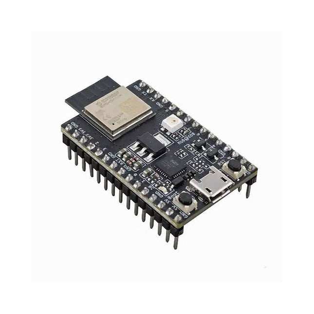
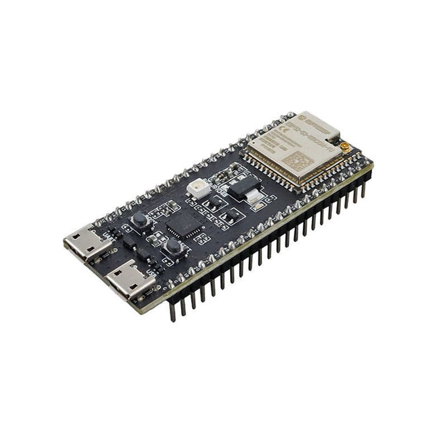
ESP32-C3-DevKitM-1 is an entry-level development board based on ESP32-C3-MINI-1, a module named for its small size. This board integrates complete Wi-Fi and Bluetooth LE functions. Most of the I/O pins on the ESP32-C3-MINI-1 module are broken out to the pin headers on both sides of this board for easy interfacing. Developers can either connect peripherals with jumper wires or mount ESP32-C3-DevKitM-1 on a breadboard. Specifications ESP32-C3-MINI-1 ESP32-C3-MINI-1 is a general-purpose Wi-Fi and Bluetooth LE combo module that comes with a PCB antenna. At the core of this module is ESP32-C3FN4, a chip that has an embedded flash of 4 MB. Since flash is packaged in the ESP32-C3FN4 chip, rather than integrated into the module, ESP32-C3-MINI-1 has a smaller package size. 5 V to 3.3 V LDO Power regulator that converts a 5 V supply into a 3.3 V output. 5 V Power On LED Turns on when the USB power is connected to the board. Pin Headers All available GPIO pins (except for the SPI bus for flash) are broken out to the pin headers on the board. For details, please see Header Block. Boot Button Download button. Holding down Boot and then pressing Reset initiates Firmware Download mode for downloading firmware through the serial port. Micro-USB Port USB interface. Power supply for the board as well as the communication interface between a computer and the ESP32-C3FN4 chip. Reset Button Press this button to restart the system. USB-to-UART Bridge Single USB-UART bridge chip provides transfer rates up to 3 Mbps. RGB LED Addressable RGB LED, driven by GPIO 8. Downloads ESP32-C3 Datasheet ESP32-C3-MINI-1 Datasheet ESP32-C3-DevKitM-1 Schematic ESP32-C3-DevKitM-1 PCB Layout ESP32-C3-DevKitM-1 Dimensions
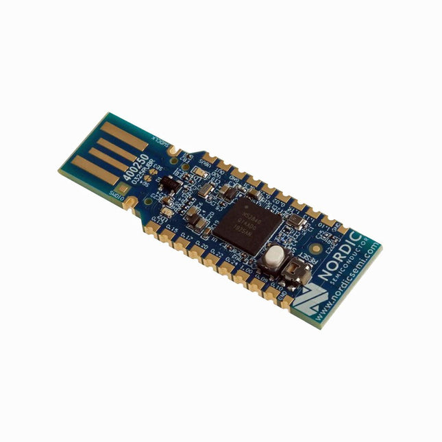
The nRF52840 dongle is a small, low-cost USB dongle that supports Bluetooth 5.3, Bluetooth mesh, Thread, ZigBee, 802.15.4, ANT and 2.4 GHz proprietary protocols. The dongle is the perfect target hardware for use with nRF Connect for Desktop as it is low-cost but still support all the short range wireless standards used with Nordic devices.
The dongle has been designed to be used as a wireless HW device together with nRF Connect for Desktop. For other use cases please do note that there is no debug support on the dongle, only support for programming the device and communicating through USB.
It is supported by most of the nRF Connect for Desktop apps and will automatically be programmed if needed. In addition custom applications can be compiled and downloaded to the dongle. It has a user programmable RGB LED, a green LED, a user programmable button as well as 15 GPIO accessible from castellated solder points along the edge. Example applications are available in the nRF5 SDK under the board name PCA10059.
The nRF52840 dongle is supported by nRF Connect for Desktop as well as programming through nRFUtil.
Features
Bluetooth 5.2 ready multiprotocol radio
2 Mbps
Long Range
Advertising Extensions
Channel Selection Algorithm #2 (CSA #2)
IEEE 802.15.4 radio support
Thread
ZigBee
Arm Cortex-M4 with floating point support
DSP instruction set
ARM CryptoCell CC310 cryptographic accelerator
15 GPIO available via edge castellation
USB interface direct to nRF52840 SoC
Integrated 2.4 GHz PCB antenna
1 user-programmable button
1 user-programmable RGB LED
1 user-programmable LED
1.7-5.5 V operation from USB or external
Downloads
Datasheet
Hardware Files
Features RP2040 microcontroller with 2 MB Flash Dual-core cortex M0+ at up to 133 MHz 264 KB multi-bank high performance SRAM External Quad-SPI Flash with eXecute In Place (XIP) High performance full-crossbar bus fabric 30 multi-function General Purpose IO (4 can be used for ADC) 1.8-3.3 V IO Voltage (NOTE. Pico IO voltage is fixed at 3.3 V) 12-bit 500 ksps Analogue to Digital Converter (ADC) Various digital peripherals 2× UART, 2× I²C, 2× SPI, 16× PWM channels 1× Timer with 4 alarms, 1× Real Time Counter 2× Programmable IO (PIO) blocks, 8 state machines total Flexible, user-programmable high-speed IO Can emulate interfaces such as SD Card and VGA Includes W5100S Supports Hardwired Internet Protocols: TCP, UDP, WOL over UDP, ICMP, IGMPv1/v2, IPv4, ARP, PPPoE Supports 4 Independent Hardware SOCKETs simultaneously Internal 16 KB Memory for TX/ RX Buffers SPI Interface Micro-USB B port for power and data (and for reprogramming the Flash) 40 pin 21x51 'DIP' style 1mm thick PCB with 0.1' through-hole pins also with edge castellations 3-pin ARM Serial Wire Debug (SWD) port 10 / 100 Ethernet PHY embedded Supports Auto Negotiation Full / Half Duplex 10 / 100 Based Built-in RJ45 (RB1-125BAG1A) Built-in LDO (LM8805SF5-33V) Downloads RP2040 Datasheet W5100S Datasheet Schematic & Part list & Gerber File C/C++ Examples CircuitPython Examples
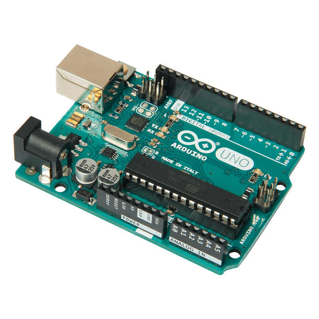
Arduino Uno is an open-source microcontroller board based on the ATmega328P. It has 14 digital input/output pins (of which 6 can be used as PWM outputs), 6 analog inputs, a 16 MHz ceramic resonator (CSTCE16M0V53-R0), a USB connection, a power jack, an ICSP header and a reset button. It contains everything needed to support the microcontroller; simply connect it to a computer with a USB cable or power it with a AC-to-DC adapter or battery to get started. You can tinker with your Uno without worring too much about doing something wrong, worst case scenario you can replace the chip for a few dollars and start over again.
'Uno' means one in Italian and was chosen to mark the release of Arduino Software (IDE) 1.0. The Uno board and version 1.0 of Arduino Software (IDE) were the reference versions of Arduino, now evolved to newer releases. The Uno board is the first in a series of USB Arduino boards, and the reference model for the Arduino platform; for an extensive list of current, past or outdated boards see the Arduino index of boards.
Specifications
Microcontroller
ATmega328P
Operating Voltage
5 V
Input Voltage (recommended)
7-12 V
Input Voltage (limit)
6-20 V
Digital I/O Pins
14 (of which 6 provide PWM output)
PWM Digital I/O Pins
6
Analog Input Pins
6
DC Current per I/O Pin
20 mA
DC Current for 3.3 V Pin
50 mA
Flash Memory
32 KB (ATmega328P) of which 0.5 KB used by bootloader
SRAM
2 KB (ATmega328P)
EEPROM
1 KB (ATmega328P)
Clock Speed
16 MHz
LED_BUILTIN
13
Dimensions
68.6 x 53.4 mm
Weight
25 g
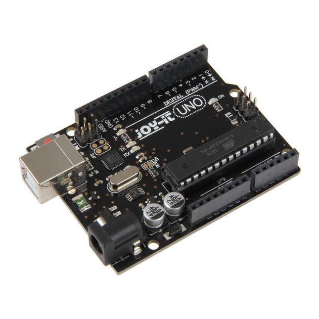
The Uno R3 board is the perfect microcontroller for those who want to enter the programming world without any fuss. Its ATMega328 microcontroller provides you with enough power for your ideas and projects. The Uno board has a USB type B connector so that you can easily use it with programs – of course via the well-known programming environment Arduino IDE. You can connect it to the power source via the USB port or alternatively use its own power connection. Please note: The CH341 driver must be installed beforehand so that Uno board is recognized by the Arduino IDE. Microcontroller ATmega 328 Clock speed 16 MHz Operating voltage 5 V Input voltage 5-10 V Digital I/O Pins 14 with PWM 6 USB 1x SPI 1x I²C 1x ICSP 1x Flash Memory 32 KB EEPROM 1x
The ESP32-S3-DevKitC-1 is an entry-level development board equipped with ESP32-S3-WROOM-1U, a general-purpose Wi-Fi + Bluetooth Low Energy MCU module that integrates complete Wi-Fi and Bluetooth Low Energy functions.
Most of the I/O pins on the module are broken out to the pin headers on both sides of this board for easy interfacing. Developers can either connect peripherals with jumper wires or mount ESP32-S3-DevKitC-1 on a breadboard.
Features
Module integrated: ESP32-S3-WROOM-1U-N8R8
Flash: 8 MB QD
PSRAM: 8 MB OT
SPI voltage: 3.3 V
Specifications
ESP32-S3-WROOM-1U
ESP32-S3-WROOM-1U is a powerful, generic Wi-Fi + Bluetooth Low Energy MCU module that has a rich set of peripherals. It provides acceleration for neural network computing and signal processing workloads. ESP32-S3-WROOM-1U comes with an external antenna connector.
5 V to 3.3 V LDO
Power regulator that converts a 5 V supply into a 3.3 V output.
Pin Headers
All available GPIO pins (except for the SPI bus for flash) are broken out to the pin headers on the board for easy interfacing and programming.
USB-to-UART Port
A Micro-USB port used for power supply to the board, for flashing applications to the chip, as well as for communication with the chip via the on-board USB-to-UART bridge.
Boot Button
Download button. Holding down Boot and then pressing Reset initiates Firmware Download mode for downloading firmware through the serial port.
Reset Button
Press this button to restart the system.
USB Port
ESP32-S3 full-speed USB OTG interface, compliant with the USB 1.1 specification. The interface is used for power supply to the board, for flashing applications to the chip, for communication with the chip using USB 1.1 protocols, as well as for JTAG debugging.
USB-to-UART Bridge
Single USB-to-UART bridge chip provides transfer rates up to 3 Mbps.
RGB LED
Addressable RGB LED, driven by GPIO38.
3.3 V Power On LED
Turns on when the USB power is connected to the board.
Downloads
Pinout
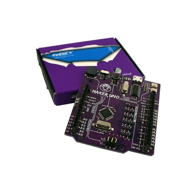
Features Piezo Buzzer: Acts as a simple audio output Micro USB Port Programmable Button 12 x LED: Provides visual output on board Specifications Microcontroller ATmega328P Programming IDE Arduino IDE Operating Voltage 5 V Digital I/O 20 PWM 6 Analog Input 6 (10-bit) UART 1 SPI 1 I2C 1 External Interrupt 2 Flash Memory 32 KB SRAM 2 KB EEPROM / Data Flash 1 KB Clock Speed 16 MHz DC Current I/O Pin 20 mA Power Supply USB only DC Current for 5 V USB Source DC Current for 3.3 V 500 mA USB to Serial Chip CH340G Programmable LED 12 at digital Pin 2 to 13 Programmable Push Button 1 at digital Pin 2 Piezo Buzzer 1 at digital Pin 8 Arduino vs Maker Uno
Features Build in USB to Serial interface Build-in PCB antenna Powered by Pineseed BL602 SoC using Pinenut model: 12S stamp 2 MB Flash USB-C connection Suitable to breadboard BIY project On board three color LEDs output Dimensions: 25.4 x 44.0 mm Note: USB cable is not included.
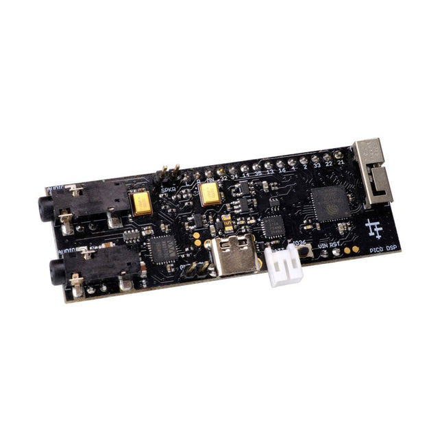
PÚCA DSP is an open-source, Arduino-compatible ESP32 development board for audio and digital signal processing (DSP) applications with expansive audio-processing features. It provides audio inputs, audio outputs, a low-noise microphone array, an integrated test-speaker option, additional memory, battery-charge management, and ESD protection all on a small, breadboard-friendly PCB.
Synthesizers, Installations, Voice UI, and More
PÚCA DSP can be used for a wide range of DSP applications, including but not limited to those in the fields of music, art, creative technology, and adaptive technology. Music-related examples include digital-music synthesis, mobile recording, Bluetooth speakers, wireless line-level directional microphones, and the design of smart musical instruments. Art-related examples include acoustic sensor networks, sound-art installations, and Internet-radio applications. Examples related to creative and adaptive technology include voice user interface (VUI) design and Web audio for the Internet of Sounds.
Compact, Integrated Design
PÚCA DSP was designed for portability. When used with an external 3.7 V rechargeable battery, it can be deployed almost anywhere or integrated into just about any device, instrument, or installation. Its design emerged from months of experimentation with various ESP32 development boards, DAC breakout boards, ADC breakout boards, Microphone breakout boards, and audio-connector breakout boards, and – despite its diminutive size – it manages to provide all of that functionality in a single board. And it dos so without compromising signal quality.
Specifications
Processor & Memory
Espressif ESP32 Pico D4 Processor
32-bit dual core 80 MHz / 160 MHz / 240 MHz
4 MB SPI Flash with 8 MB additional PSRAM (Original Edition)
Wireless 2.4 GHz Wi-Fi 802.11b/g/n
Bluetooth BLE 4.2
3D Antenna
Audio
Wolfson WM8978 Stereo Audio Codec
Audio Line In on 3.5 mm stereo onnector
Audio Headphone / Line Out on 3.5 mm stereo connector
Stereo Aux Line In, Audio Mono Out routed to GPIO Header
2x Knowles SPM0687LR5H-1 MEMS Microphones
ESD protection on all audio inputs and outputs
Support for 8, 11.025, 12, 16, 22.05, 24, 32, 44.1 and 48 kHz sample rates
1 W Speaker Driver, routed to GPIO Header
DAC SNR 98 dB, THD -84 dB (‘A’ weighted @ 48 kHz)
ADC SNR 95 dB, THD -84 dB (‘A’ weighted @ 48 kHz)
Line input impedance: 1 MOhm
Line output impedance: 33 Ohm
Form Factor and Connectivity
Breadboard friendly
70 x 24 mm
11x GPIO pins broken out to 2.54 mm pitch header, with access to both ESP32 ADC channels, JTAG and capacitive touch pins
USB 2.0 over USB Type C connector
Power
3.7/4.2 V Lithium Polymer Rechargeable Battery, USB or external 5 V DC power source
ESP32 and Audio Codec can be placed into low power modes under software control
Battery voltage level detection
ESD protection on USB data bus
Downloads
GitHub
Datasheet
Links
Crowd Supply Campaign (includes FAQs)
Hardware Overview
Programming the Board
The Audio Codec
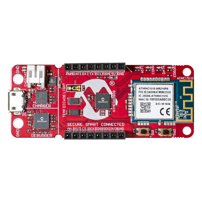
The AVR-IoT WA development board combines a powerful ATmega4808 AVR MCU, an ATECC608A CryptoAuthentication secure element IC and the fully certified ATWINC1510 Wi-Fi network controller – which provides the most simple and effective way to connect your embedded application to Amazon Web Services (AWS). The board also includes an on-board debugger, and requires no external hardware to program and debug the MCU.
Out of the box, the MCU comes preloaded with a firmware image that enables you to quickly connect and send data to the AWS platform using the on-board temperature and light sensors. Once you are ready to build your own custom design, you can easily generate code using the free software libraries in Atmel START or MPLAB Code Configurator (MCC).
The AVR-IoT WA board is supported by two award-winning Integrated Development Environments (IDEs) – Atmel Studio and Microchip MPLAB X IDE – giving you the freedom to innovate with your environment of choice.
Features
ATmega4808 microcontroller
Four user LED’s
Two mechanical buttons
mikroBUS header footprint
TEMT6000 Light sensor
MCP9808 Temperature sensor
ATECC608A CryptoAuthentication™ device
WINC1510 WiFi Module
On-board Debugger
Auto-ID for board identification in Atmel Studio and Microchip MPLAB X
One green board power and status LED
Programming and debugging
Virtual COM port (CDC)
Two DGI GPIO lines
USB and battery powered
Integrated Li-Ion/LiPo battery charger
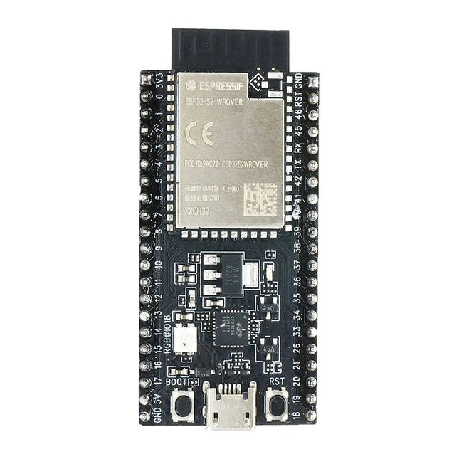
ESP32-S2-Saola-1R is a small-sized ESP32-S2 based development board. Most of the I/O pins are broken out to the pin headers on both sides for easy interfacing. Developers can either connect peripherals with jumper wires or mount ESP32-S2-Saola-1R on a breadboard.ESP32-S2-Saola-1R is equipped with the ESP32-S2-WROVER module, a powerful, generic Wi-Fi MCU module that has a rich set of peripherals. It is an ideal choice for a wide variety of application scenarios relating to Internet of Things (IoT), wearable electronics and smart home. The board a PCB antenna and features a 4 MB external SPI flash and an additional 2 MB SPI Pseudo static RAM (PSRAM).FeaturesMCU
ESP32-S2 embedded, Xtensa® single-core 32-bit LX7 microprocessor, up to 240 MHz
128 KB ROM
320 KB SRAM
16 KB SRAM in RTC
WiFi
802.11 b/g/n
Bit rate: 802.11n up to 150 Mbps
A-MPDU and A-MSDU aggregation
0.4 µs guard interval support
Center frequency range of operating channel: 2412 ~ 2484 MHz
Hardware
Interfaces: GPIO, SPI, LCD, UART, I²C, I²S, Camera interface, IR, pulse counter, LED PWM, TWAI (compatible with ISO 11898-1), USB OTG 1.1, ADC, DAC, touch sensor, temperature sensor
40 MHz crystal oscillator
4 MB SPI flash
Operating voltage/Power supply: 3.0 ~ 3.6 V
Operating temperature range: –40 ~ 85 °C
Dimensions: 18 × 31 × 3.3 mm
Applications
Generic Low-power IoT Sensor Hub
Generic Low-power IoT Data Loggers
Cameras for Video Streaming
Over-the-top (OTT) Devices
USB Devices
Speech Recognition
Image Recognition
Mesh Network
Home Automation
Smart Home Control Panel
Smart Building
Industrial Automation
Smart Agriculture
Audio Applications
Health Care Applications
Wi-Fi-enabled Toys
Wearable Electronics
Retail & Catering Applications
Smart POS Machines
The SparkFun RedBoard Qwiic is an Arduino-compatible board that combines features of different Arduinos with the Qwiic Connect System.
Features
ATmega328 microcontroller with Optiboot Bootloader
R3 Shield Compatible
CH340C Serial-USB Converter
3.3 V to 5 V Voltage Level Jumper
A4 / A5 Jumpers
AP2112 Voltage Regulator
ISP Header
Input voltage: 7 V - 15 V
1 Qwiic Connector
16 MHz Clock Speed
32 k Flash Memory
All SMD Construction
Improved Reset Button
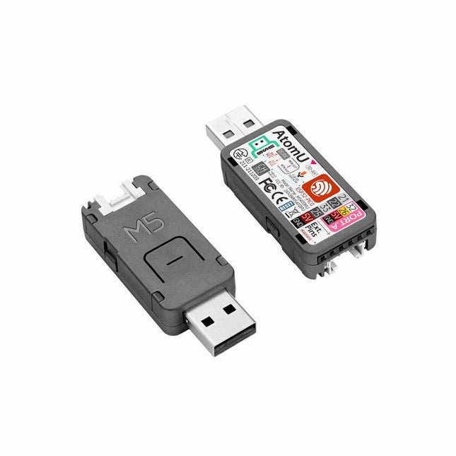
ATOM U is a compact low-power consumption speech recognition IoT development kit. It adopts an ESP32 chipset, equipped with 2 low-power Xtensa 32-bit LX6 microprocessors with the main frequency of up to 240 MHz. Built-in USB-A interface, IR emitter, programmable RGB LED. Plug-and-play, easy to upload and download programs. Integrated Wi-Fi and digital microphone SPM1423 (I2S) for the clear sound record. suitable for HMI, Speech-to-Text (STT). Low-code development ATOM U supports UIFlow graphical programming platform, scripting-free, cloud push; Fully compatible with Arduino, MicroPython, ESP32-IDF, and other mainstream development platforms, to quickly build various applications. High integration ATOM U contains a USB-A port for programming/power supply, IR emitter, programmable RGB LED x1, button x1; Finely tuned RF circuit, providing stable and reliable wireless communication. Strong expandability ATOM U is easy access to M5Stack's hardware and software system. Features ESP32-PICO-D4 (2.4GHz Wi-Fi dual mode) Integrated programmable RGB LED and button Compact design Built-in IR emitter Expandable pinout and GROVE port Development platform: UIFlow MicroPython Arduino Specifications ESP32-PICO-D4 240MHz dual core, 600 DMIPS, 520KB SRAM, 2.4G Wi-Fi Microphone SPM1423 Microphone sensitivity 94 dB SPL@1 KHz Typical value: -22 dBFS Microphone signal-to-noise ratio 94 dB SPL@1 KHz, A-weighted Typical value: 61.4 dB Standby working current 40.4 mA Support input sound frequency 100 Hz ~ 10 KHz Support PDM clock frequency 1.0 ~ 3.25 MHz Weight 8.4 g Product size 52 x 20 x 10 mm Downloads Documentation
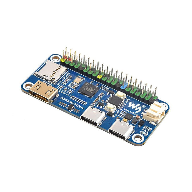
Waveshare RP2040-PiZero is a high-performance and cost-effective microcontroller board with onboard DVI interface, TF card slot and PIO-USB port, compatible with Raspberry Pi 40-pin GPIO header, easy to develop and integrate into the products.
Features
RP2040 microcontroller chip designed by Raspberry Pi
Dual-core ARM Cortex M0+ processor, flexible clock running up to 133 MHz
264 KB of SRAM, and 16 MB of onboard Flash memory
Onboard DVI interface can drive most HDMI screens (DVI compatibility required)
Supports using as a USB host or slave via onboard PIO-USB port
Onboard TF card slot for reading and writing TF card
Onboard Lithium battery recharge/discharge header, suitable for mobile scenarios
USB 1.1 with device and host support
Drag-and-drop programming using mass storage over USB
Low-power sleep and dormant modes
2x SPI, 2x I²C, 2x UART, 4x 12-bit ADC, 16x controllable PWM channels
Accurate clock and timer on-chip
Temperature sensor
Accelerated floating-point libraries on-chip
Downloads
Wiki
The OKdo E1 is an ultra-low-cost Development Board based on the NXP LPC55S69JBD100 dual-core Arm Cortex-M33 microcontroller. The E1 board is perfect for Industrial IoT, building control and automation, consumer electronics, general embedded and secure applications.
Features
Processor with Arm TrustZone, Floating Point Unit (FPU) and Memory Protection Unit (MPU)
CASPER Crypto co-processor to enable hardware acceleration for certain asymmetric cryptographic algorithms
PowerQuad Hardware Accelerator for fixed and floating point DSP functions
SRAM Physical Unclonable Function (PUF) for key generation, storage and reconstruction
PRINCE module for real-time encryption and decryption of flash data
AES-256 and SHA2 engines
Up to Nine Flexcomm interfaces. Each Flexcomm interface can be selected by software to be a USART, SPI, I²C, and I²S interface
USB 2.0 High-Speed Host/Device controller with on-chip PHY
USB 2.0 Full-Speed Host/Device controller with on-chip PHY
Up to 64 GPIOs
Secure digital input/output (SD/MMC and SDIO) card interface
Specifications
LPC55S69JBD100 640kbyte flash microcontroller
In-built CMSIS-DAP v1.0.7 debugger based on LPC11U35
Internal PLL support up to 100MHz operation, 16MHz can be mounted for full 150MHz operation.
SRAM 320kB
32kHz crystal for real-time clock
4 user switches
3-colour LED
User USB connector
2-off 16-way expansion connectors
UART over USB virtual COM port
LuckFox Pico Mini is a compact Linux micro development board based on the Rockchip RV1103 chip, providing a simple and efficient development platform for developers. It supports a variety of interfaces, including MIPI CSI, GPIO, UART, SPI, I²C, USB, etc., which is convenient for quick development and debugging.
Features
Single-core ARM Cortex-A7 32-bit core with integrated NEON and FPU
Built-in Rockchip self-developed 4th generation NPU, features high computing precision and supports int, int8, and int16 hybrid quantization. The computing power of int8 is 0.5 TOPS, and up to 1.0 TOPS with int4
Built-in self-developed third-generation ISP3.2, supports 4-Megapixel, with multiple image enhancement and correction algorithms such as HDR, WDR, multi-level noise reduction, etc.
Features powerful encoding performance, supports intelligent encoding mode and adaptive stream saving according to the scene, saves more than 50% bit rate of the conventional CBR mode so that the images from camera are high-definition with smaller size, double the storage space
Built-in RISC-V MCU supports low power consumption and fast start-up, supports 250 ms fast picture capture and loading Al model library at the same time to realize face recognition "in one second"
Built-in 16-bit DRAM DDR2, which is capable of sustaining demanding memory bandwidths
Integrated with built-in POR, audio codec and MAC PHY
Specifications
Processor
ARM Cortex-A7, single-core 32-bit CPU, 1.2 GHz, with NEON and FPU
NPU
Rockchip 4th-gen NPU, supports int4, int8, int16; up to 1.0 TOPS (int4)
ISP
Third-gen ISP3.2, up to 4 MP input at 30fps, HDR, WDR, noise reduction
RAM
64 MB DDR2
Storage
128 MB SPI NAND Flash
USB
USB 2.0 Host/Device via Type-C
Camera Interface
MIPI CSI 2-lane
GPIO Pins
17 GPIO pins
Power Consumption
Low power, RISC-V MCU for fast startup
Dimensions
28 x 21 mm
Downloads
Wiki
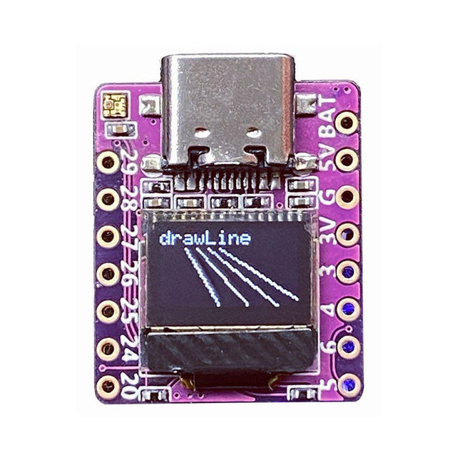
Arduino, MicroPython, and CircuitPython-compatible compact development board powered by Raspberry Pi RP2040
RP2040-0.42LCD is a high-performance development board with integrated 0.42" LCD (70x40 resolution) with flexible digital interfaces.
It incorporates Raspberry Pi's RP2040 microcontroller chip. The RP2040 features a dual-core Arm Cortex-M0+ processor clocked at 133 MHz with 264 KB internal SRAM and 2 MB flash storage.
Specifications
SoC
Raspberry Pi RP2040 dual-core Cortex-M0+ microcontroller at up to 125 MHz, with 264 KB SRAM
Storage
2 MB SPI flash
Display
0.42-inch OLED
USB
1x USB Type-C port for power and programming
Expansion
– Qwiic I²C connector– 7-pin and 8-pin headers with up to 11x GPIOs, 2x SPI, 2x I²C, 4x ADC, 1x UART, 5 V, 3.3 V, VBAT, GND
Misc
– Reset and Boot buttons– RGB LED, power LED
Power supply
– 5 V via USB-C port or Vin– VBAT pin for battery input– 3.3 V regulator with 500 mA peak output
Dimensions
23.5 x 18 mm
Weight
2.5 g
Downloads
GitHub
The LILYGO T-Display-S3 Long is a versatile development board powered by the ESP32-S3R8 dual-core LX7 microprocessor. It features a 3.4-inch capacitive touch TFT LCD with a resolution of 180x640 pixels, providing a responsive interface for various applications.
This board is ideal for developers seeking a compact yet powerful solution for projects requiring touch input and wireless communication. Its compatibility with popular programming environments ensures a smooth development experience.
Specifications
MCU
ESP32-S3R8 Dual-core LX7 microprocessor
Wireless Connectivity
Wi-Fi 802.11, BLE 5 + BT Mesh
Programming Platform
Arduino IDE, VS Code
Flash
16 MB
PSRAM
8 MB
Bat voltage detection
IO02
Onboard functions
Boot + Reset Button, Battery Switch
Display
3.4" Capacitive Touch TFT LCD
Color depth
565, 666
Resolution
180 x 640 (RGB)
Working power supply
3.3 V
Interface
QSPI
Included
1x T-Display S3 Long
1x Power cable
2x STEMMA QT/Qwiic interface cable (P352)
1x Female pin (double row)
Downloads
GitHub
The EC200U-EU C4-P01 development board features the EC200U-EU LTE Cat 1 wireless communication module, offering a maximum data rate of up to 10 Mbps for downlink and 5 Mbps for uplink. It supports multi-mode and multi-band communication, making it a cost-effective solution.
The board is designed in a compact and unified form factor, compatible with the Quectel multi-mode LTE Standard EC20-CE. It includes an onboard USB-C port, allowing for easy development with just a USB-C cable.
Additionally, the board is equipped with a 40-pin GPIO header that is compatible with most Raspberry Pi HATs.
Features
Equipped with EC200U-EU LTE Cat 1 wireless communication module, multi-mode & multi-band support
Onboard 40-Pin GPIO header, compatible with most Raspberry Pi HATs
5 LEDs for indicating module operating status
Supports TCP, UDP, PPP, NITZ, PING, FILE, MQTT, NTP, HTTP, HTTPS, SSL, FTP, FTPS, CMUX, MMS protocols, etc.
Supports GNSS positioning (GPS, GLONASS, BDS, Galileo, QZSS)
Onboard Nano SIM card slot and eSIM card slot, dual card single standby
Onboard MIPI connector for connecting MIPI screen and is fully compatible with Raspberry Pi peripherals
Onboard camera connector, supports customized SPI cameras with a maximum of 300,000 pixels
Provides tools such as QPYcom, Thonny IDE plugin, and VSCode plugin, etc. for easy learning and development
Comes with online development resources and manual (example in QuecPython)
Specifications
Applicable Regions
Europe, Middle East, Africa, Australia, New Zealand, Brazil
LTE-FDD
B1, B3, B5, B7, B8, B20, B28
LTE-TDD
B38, B40, B41
GSM / GPRS / EDGE
GSM: B2, B3, B5, B8
GNSS
GPS, GLONASS, BDS, Galileo, QZSS
Bluetooth
Bluetooth 4.2 (BR/EDR)
Wi-Fi Scan
2.4 GHz 11b (Rx)
CAT 1
LTE-FDD: DL 10 Mbps; UL 5 Mbps
LTE-TDD: DL 8.96 Mbps; UL 3.1 Mbps
GSM / GPRS / EDGE
GSM: DL 85.6 Kbps; UL 85.6 Kbps
USB-C Port
Supports AT commands testing, GNSS positioning, firmware upgrading, etc.
Communication Protocol
TCP, UDP, PPP, NITZ, PING, FILE, MQTT, NTP, HTTP, HTTPS, SSL, FTP, FTPS, CMUX, MMS
SIM Card
Nano SIM and eSIM, dual card single standby
Indicator
P01: Module Pin 1, default as EC200A-XX PWM0
P05: Module Pin 5, NET_MODE indicator
SCK1: SIM1 detection indicator, lights up when SIM1 card is inserted
SCK2: SIM2 detection indicator, lights up when SIM2 card is inserted
PWR: Power indicator
Buttons
PWK: Power ON/OFF
RST: Reset
BOOT: Forcing into firmware burning mode
USB ON/OFF: USB power consumption detection switch
Antenna Connectors
LTE main antenna + DIV / WiFi (scanning only) / Bluetooth antenna + GNSS antenna
Operating Temperature
−30~+75°C
Storage Temperature
−45~+90°C
Downloads
Wiki
Quectel Resources
The SparkFun RP2040 mikroBUS Development Board is a low-cost, high performance platform with flexible digital interfaces featuring the Raspberry Pi Foundation's RP2040 microcontroller. Besides the Thing Plus or Feather PTH pin layout, the board also includes a microSD card slot, 16 MB (128 Mbit) flash memory, a JST single cell battery connector (with a charging circuit and fuel gauge sensor), an addressable WS2812 RGB LED, JTAG PTH pins, four (4-40 screw) mounting holes, our signature Qwiic connectors, and a mikroBUS socket. The mikroBUS standard was developed by MikroElektronika. Similar to Qwiic and MicroMod interfaces, the mikroBUS socket provides a standardized connection for add-on Click boards to be attached to a development board and is comprised of a pair of 8-pin female headers with a standardized pin configuration. The pins consist of three groups of communications pins (SPI, UART and I²C), six additional pins (PWM, Interrupt, Analog input, Reset and Chip select), and two power groups (3.3 V and 5 V). The RP2040 is supported with both C/C++ and MicroPython cross-platform development environments, including easy access to runtime debugging. It has UF2 boot and floating-point routines baked into the chip. While the chip has a large amount of internal RAM, the board includes an additional 16 MB of external QSPI flash memory to store program code. The RP2040 contains two ARM Cortex-M0+ processors (up to 133 MHz) and features: 264 kB of embedded SRAM in six banks 6 dedicated IO for SPI Flash (supporting XIP) 30 multifunction GPIO: Dedicated hardware for commonly used peripherals Programmable IO for extended peripheral support Four 12-bit ADC channels with internal temperature sensor (up to 0.5 MSa/s) USB 1.1 Host/Device functionality Features (SparkFun RP2040 mikroBUS Dev. Board) Raspberry Pi Foundation's RP2040 microcontroller 18 Multifunctional GPIO Pins Four available 12-bit ADC channels with internal temperature sensor (500kSa/s) Up to eight 2-channel PWM Up to two UARTs Up to two I²C buses Up to two SPI buses Thing Plus (or Feather) Pin Layout: 28 PTH Pins USB-C Connector: USB 1.1 Host/Device functionality 2-pin JST Connector for a LiPo Battery (not included): 500mA charging circuit 4-pin JST Qwiic Connector LEDs:
PWR - Red 3.3V power indicator
CHG - Yellow battery charging indicator
25 - Blue status/test LED (GPIO 25)
WS2812 - Addressable RGB LED (GPIO 08) Buttons: Boot Reset JTAG PTH Pins 16MB QSPI Flash Memory µSD Card Slot mikroBUS Socket Dimensions: 3.7' x 1.2' Four Mounting Holes: 4-40 screw compatible Downloads Schematic Eagle Files Board Dimensions Hookup Guide Qwiic Info Page GitHub Hardware Repository
The Milk-V Duo 256M is an ultra-compact embedded development platform based on the SG2002 chip. It can run Linux and RTOS, providing a reliable, low-cost, and high-performance platform for professionals, industrial ODMs, AIoT enthusiasts, DIY hobbyists, and creators.
This board is an upgraded version of Duo with a memory boost to 256M, catering to applications demanding larger memory capacities. The SG2002 elevates computational power to 1.0 TOPS @ INT8. It enables seamless switching between RISC-V/ARM architectures and supports simultaneous operation of dual systems. Additionally, it includes an array of rich GPIO interfaces such as SPI, UART, suitable for a wide range of hardware development in edge intelligent monitoring, including IP cameras, smart peephole locks, visual doorbells, and more.
SG2002 is a high-performance, low-power chip designed for various product fields such as edge intelligent surveillance IP cameras, smart door locks, visual doorbells, and home intelligence. It integrates H.264 video compression and decoding, H.265 video compression encoding, and ISP capabilities. It supports multiple image enhancement and correction algorithms such as HDR wide dynamic range, 3D noise reduction, defogging, and lens distortion correction, providing customers with professional-grade video image quality.
The chip also incorporates a self-developed TPU, delivering 1.0 TOPS of computing power under 8-bit integer operations. The specially designed TPU scheduling engine efficiently provides high-bandwidth data flow for all tensor processing unit cores. Additionally, it offers users a powerful deep learning model compiler and software SDK development kit. Leading deep learning frameworks like Caffe and Tensorflow can be easily ported to its platform. Furthermore, it includes security boot, secure updates, and encryption, providing a series of security solutions from development, mass production, to product applications.
The chip integrates an 8-bit MCU subsystem, replacing the typical external MCU to achieve cost-saving and power efficiency goals.
Specifications
SoC
SG2002
RISC-V CPU
C906 @ 1 Ghz + C906 @ 700 MHz
Arm CPU
1x Cortex-A53 @ 1 GHz
MCU
8051 @ 6 KB SRAM
Memory
256 MB SIP DRAM
TPU
1.0 TOPS @ INT8
Storage
1x microSD connector or 1x SD NAND on board
USB
1x USB-C for power and data, USB Pads available
CSI
1x 16P FPC connector (MIPI CSI 2-lane)
Sensor Support
5 M @ 30 fps
Ethernet
100 Mbps Ethernet with PHY
Audio
Via GPIO Pads
GPIO
Up to 26x GPIO Pads
Power
5 V/1 A
OS Support
Linux, RTOS
Dimensions
21 x 51 mm
Downloads
Documentation
GitHub
The FRDM-MCXN947 is a compact and versatile development board designed for rapid prototyping with MCX N94 and N54 microcontrollers. It features industry-standard headers for easy access to the MCU's I/Os, integrated open-standard serial interfaces, external flash memory, and an onboard MCU-Link debugger.
Specifications
Microcontroller
MCX-N947 Dual Arm Cortex-M33 cores @ 150 MHz each with optimized performance efficiency, up to 2 MB dual-bank flash with optional full ECC RAM, External flash
Accelerators: Neural Processing Unit, PowerQuad, Smart DMA, etc.
Memory Expansion
*DNP Micro SD card socket
Connectivity
Ethernet Phy and connector
HS USB-C connectors
SPI/I²C/UART connector (PMOD/mikroBUS, DNP)
WiFi connector (PMOD/mikroBUS, DNP)
CAN-FD transceiver
Debug
On-board MCU-Link debugger with CMSIS-DAP
JTAG/SWD connector
Sensor
P3T1755 I³C/I²C Temp Sensor, Touch Pad
Expansion Options
Arduino Header (with FRDM expansion rows)
FRDM Header
FlexIO/LCD Header
SmartDMA/Camera Header
Pmod *DNP
mikroBUS
User Interface
RGB user LED, plus Reset, ISP, Wakeup buttons
Included
1x FRDM-MCXN947 Development Board
1x USB-C Cable
1x Quick Start Guide
Downloads
Datasheet
Block diagram
The LuckFox Pico Ultra is a compact single-board computer (SBC) powered by the Rockchip RV1106G3 chipset, designed for AI processing, multimedia, and low-power embedded applications.
It comes equipped with a built-in 1 TOPS NPU, making it ideal for edge AI workloads. With 256 MB RAM, 8 GB onboard eMMC storage, integrated WiFi, and support for the LuckFox PoE module, the board delivers both performance and versatility across a wide range of use cases.
Running Linux, the LuckFox Pico Ultra supports a variety of interfaces – including MIPI CSI, RGB LCD, GPIO, UART, SPI, I²C, and USB – providing a simple and efficient development platform for applications in smart home, industrial control, and IoT.
Specifications
Chip
Rockchip RV1106G3
Processor
Cortex-A7 1.2 GHz
Neural Network Processor (NPU)
1 TOPS, supports int4, int8, int16
Image Processor (ISP)
Max input 5M @30fps
Memory
256 MB DDR3L
WiFi + Bluetooth
2.4GHz WiFi-6 Bluetooth 5.2/BLE
Camera Interface
MIPI CSI 2-lane
DPI Interface
RGB666
PoE Interface
IEEE 802.3af PoE
Speaker interface
MX1.25 mm
USB
USB 2.0 Host/Device
GPIO
30 GPIO pins
Ethernet
10/100M Ethernet controller and embedded PHY
Default Storage Medium
eMMC (8 GB)
Included
1x LuckFox Pico Ultra W
1x LuckFox PoE module
1x IPX 2.4G 2 db antenna
1x USB-A to USB-C cable
1x Screws pack
Downloads
Wiki