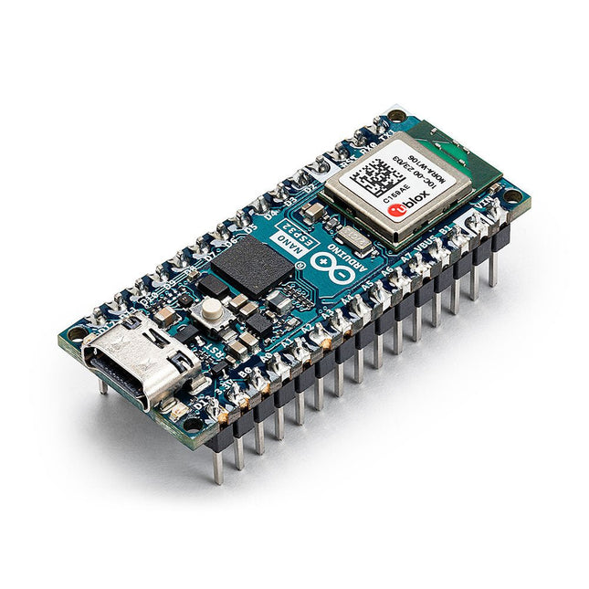
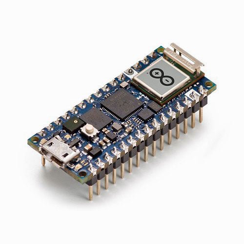
The Arduino Nano ESP32 is a Nano form factor board based on the ESP32-S3 (embedded in the NORA-W106-10B from u-blox). This is the first Arduino board to be based fully on an ESP32, and features Wi-Fi, Bluetooth LE, debugging via native USB in the Arduino IDE as well as low power.
The Nano ESP32 is compatible with the Arduino IoT Cloud, and has support for MicroPython. It is an ideal board for getting started with IoT development.
Features
Tiny footprint: Designed with the well-known Nano form factor in mind, this board's compact size makes it perfect for embedding in standalone projects.
Wi-Fi and Bluetooth: Harness the power of the ESP32-S3 microcontroller, well-known in the IoT realm, with full Arduino support for wireless and Bluetooth connectivity.
Arduino and MicroPython support: Seamlessly switch between Arduino and MicroPython programming with a few simple steps.
Arduino IoT Cloud compatible: Quickly and easily create IoT projects with just a few lines of code. The setup takes care of security, allowing you to monitor and control your project from anywhere using the Arduino IoT Cloud app.
HID support: Simulate human interface devices, such as keyboards or mice, over USB, opening up new possibilities for interacting with your computer.
Specifications
Microcontroller
u-blox NORA-W106 (ESP32-S3)
USB connector
USB-C
Pins
Built-in LED pins
13
Built-in RGB LED pins
14-16
Digital I/O pins
14
Analog input pins
8
PWM pins
5
External interrupts
All digital pins
Connectivity
Wi-Fi
u-blox NORA-W106 (ESP32-S3)
Bluetooth
u-blox NORA-W106 (ESP32-S3)
Communication
UART
2x
I²C
1x, A4 (SDA), A5 (SCL)
SPI
D11 (COPI), D12 (CIPO), D13 (SCK). Use any GPIO for Chip Select (CS)
Power
I/O Voltage
3.3 V
Input voltage (nominal)
6-21 V
Source Current per I/O pin
40 mA
Sink Current per I/O pin
28 mA
Clock speed
Processor
Up to 240 MHz
Memory
ROM
384 kB
SRAM
512 kB
External Flash
128 Mbit (16 MB)
Dimensions
18 x 45 mm
Downloads
Datasheet
Schematics
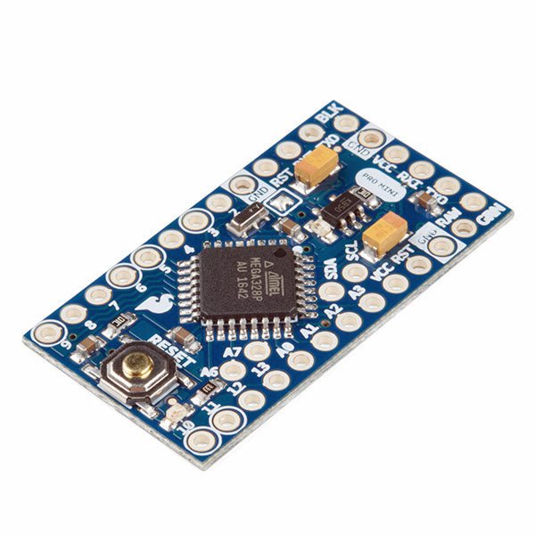
The Arduino Pro Mini is a microcontroller board based on the ATmega328P. It has 14 digital input/output pins (of which 6 can be used as PWM outputs), 6 analog inputs, an on-board resonator, a reset button, and holes for mounting pin headers. A six pin header can be connected to an FTDI cable or Sparkfun breakout board to provide USB power and communication to the board. The Arduino Pro Mini is intended for semi-permanent installation in objects or exhibitions. The board comes without pre-mounted headers, allowing the use of various types of connectors or direct soldering of wires. The pin layout is compatible with the Arduino Mini. The Arduino Pro Mini was designed and is manufactured by SparkFun Electronics. Specifications Microcontroller ATmega328P Board Power Supply 5-12 V Circuit Operating Voltage 5 V Digital I/O Pins 14 PWM Pins 6 UART 1 SPI 1 I²C 1 Analog Input Pins 6 External Interrupts 2 DC Current per I/O Pin 40 mA Flash Memory 32 KB of which 2 KB used by bootloader SRAM 2 KB EEPROM 1 KB Clock Speed 16 MHz Dimensions 18 x 33.3 mm (0.7 x 1.3') Downloads Eagle files Schematics
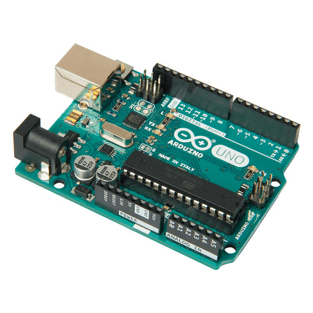
Arduino Uno is an open-source microcontroller board based on the ATmega328P. It has 14 digital input/output pins (of which 6 can be used as PWM outputs), 6 analog inputs, a 16 MHz ceramic resonator (CSTCE16M0V53-R0), a USB connection, a power jack, an ICSP header and a reset button. It contains everything needed to support the microcontroller; simply connect it to a computer with a USB cable or power it with a AC-to-DC adapter or battery to get started. You can tinker with your Uno without worring too much about doing something wrong, worst case scenario you can replace the chip for a few dollars and start over again.
'Uno' means one in Italian and was chosen to mark the release of Arduino Software (IDE) 1.0. The Uno board and version 1.0 of Arduino Software (IDE) were the reference versions of Arduino, now evolved to newer releases. The Uno board is the first in a series of USB Arduino boards, and the reference model for the Arduino platform; for an extensive list of current, past or outdated boards see the Arduino index of boards.
Specifications
Microcontroller
ATmega328P
Operating Voltage
5 V
Input Voltage (recommended)
7-12 V
Input Voltage (limit)
6-20 V
Digital I/O Pins
14 (of which 6 provide PWM output)
PWM Digital I/O Pins
6
Analog Input Pins
6
DC Current per I/O Pin
20 mA
DC Current for 3.3 V Pin
50 mA
Flash Memory
32 KB (ATmega328P) of which 0.5 KB used by bootloader
SRAM
2 KB (ATmega328P)
EEPROM
1 KB (ATmega328P)
Clock Speed
16 MHz
LED_BUILTIN
13
Dimensions
68.6 x 53.4 mm
Weight
25 g
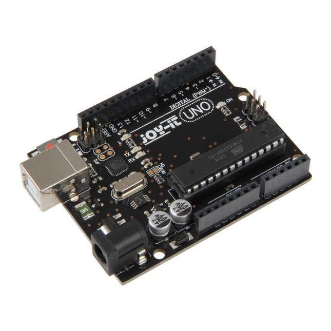
The Uno R3 board is the perfect microcontroller for those who want to enter the programming world without any fuss. Its ATMega328 microcontroller provides you with enough power for your ideas and projects. The Uno board has a USB type B connector so that you can easily use it with programs – of course via the well-known programming environment Arduino IDE. You can connect it to the power source via the USB port or alternatively use its own power connection. Please note: The CH341 driver must be installed beforehand so that Uno board is recognized by the Arduino IDE. Microcontroller ATmega 328 Clock speed 16 MHz Operating voltage 5 V Input voltage 5-10 V Digital I/O Pins 14 with PWM 6 USB 1x SPI 1x I²C 1x ICSP 1x Flash Memory 32 KB EEPROM 1x
The Arduino Nano RP2040 Connect is an RP2040-based Arduino board equipped with Wi-Fi (802.11b/g/n) and Bluetooth 4.2.
Besides wireless connectivity the board comes with a microphone for sound and voice activation and a six-axis smart motion sensor with AI capabilities. An RGB LED is available too. 22 GPIO ports (20 with PWM support and eight analogue inputs) let the user control e.g. relays, motors and LEDs and read switches and other sensors.
Program memory is plentiful with 16 MB of flash memory, more than enough room for storing many webpages or other data.
Specifications
Microcontroller
Raspberry Pi RP2040
USB connector
Micro USB
Pins
Built-in LED pins
13
Digital I/O pins
20
Analog Input pins
8
PWM pins
20 (Except A6, A7)
External interrupts
20 (Except A6, A7)
Connectivity
Wi-Fi
Nina W102 uBlox module
Bluetooth
Nina W102 uBlox module
Secure element
ATECC608A-MAHDA-T Crypto IC
Sensors
IMU
LSM6DSOXTR (6-axis)
Microphone
MP34DT05
Communication
UART
Yes
I²C
Yes
SPI
Yes
Power
Circuit operating voltage
3.3 V
Input Voltage (VIN)
5-21 V
DC Current per I/O pin
4 mA
Clock speed
Processor
133 MHz
Memory
AT25SF128A-MHB-T
16 MB Flash IC
Nina W102 uBlox module
448 KB ROM, 520 KB SRAM, 16 MB Flash
Dimensions
45 x 18 mm
Weight
6 g
Downloads
Schematics
Pinout
Datasheet
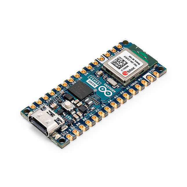
The Arduino Nano ESP32 (with and without headers) is a Nano form factor board based on the ESP32-S3 (embedded in the NORA-W106-10B from u-blox). This is the first Arduino board to be based fully on an ESP32, and features Wi-Fi, Bluetooth LE, debugging via native USB in the Arduino IDE as well as low power. The Nano ESP32 is compatible with the Arduino IoT Cloud, and has support for MicroPython. It is an ideal board for getting started with IoT development. Features
Tiny footprint: Designed with the well-known Nano form factor in mind, this board's compact size makes it perfect for embedding in standalone projects.
Wi-Fi and Bluetooth: Harness the power of the ESP32-S3 microcontroller, well-known in the IoT realm, with full Arduino support for wireless and Bluetooth connectivity.
Arduino and MicroPython support: Seamlessly switch between Arduino and MicroPython programming with a few simple steps.
Arduino IoT Cloud compatible: Quickly and easily create IoT projects with just a few lines of code. The setup takes care of security, allowing you to monitor and control your project from anywhere using the Arduino IoT Cloud app.
HID support: Simulate human interface devices, such as keyboards or mice, over USB, opening up new possibilities for interacting with your computer. Specifications Microcontroller u-blox NORA-W106 (ESP32-S3) USB connector USB-C Pins Built-in LED pins 13 Built-in RGB LED pins 14-16 Digital I/O pins 14 Analog input pins 8 PWM pins 5 External interrupts All digital pins Connectivity Wi-Fi u-blox NORA-W106 (ESP32-S3) Bluetooth u-blox NORA-W106 (ESP32-S3) Communication UART 2x I²C 1x, A4 (SDA), A5 (SCL) SPI D11 (COPI), D12 (CIPO), D13 (SCK). Use any GPIO for Chip Select (CS) Power I/O Voltage 3.3 V Input voltage (nominal) 6-21 V Source Current per I/O pin 40 mA Sink Current per I/O pin 28 mA Clock speed Processor Up to 240 MHz Memory ROM 384 kB SRAM 512 kB External Flash 128 Mbit (16 MB) Dimensions 18 x 45 mm Downloads Datasheet Schematics
The Arduino Giga R1 WiFi brings the power of the STM32H7 to the same form factor as the popular Mega and Due, being the first Mega board to include onboard Wi-Fi and Bluetooth connectivity.
The board provides 76 digital inputs/outputs (12 with PWM capability), 14 analog inputs and 2 analog outputs (DAC) all easily accessible via pin headers. The STM32 microprocessor with dual-core Cortex-M7 and Cortex-M4, together with onboard memory and audio jack enables you to perform machine learning and signal processing on the edge.
Microcontroller (STM32H747XI)
This dual core 32-bits microcontroller allows you have two brain talking to each other (a Cortex-M7 at 480 MHz and a Cortex-M4 at 240 MHz) you can even run micropython in one and Arduino in the other.
Wireless communication (Murata 1DX)
Whether you prefer Wi-Fi or Bluetooth, the Giga R1 WiFi got you covered. You can even quickly connect to the Arduino IoT Cloud and keep track of your project remotely. And if you are concerned about the security of the communication, the ATECC608A keeps everything under control.
Hardware ports and communication
Following the legacy of the Arduino Mega and the Arduino Due, the Giga R1 WiFi has 4x UARTs (hardware serial ports), 3x I²C ports (1 more than its predecessors), 2x SPI ports (1 more than its predecessors), 1x FDCAN.
GPIOs and extra pins
By keeping the same form factor of the Mega and the Due, you can easily adapt your custom made shields to the Giga R1 WiFi (remember this board works at 3.3 V though!). Also, additional headers have been added so that the total number of GPIO pins is now 76, and two new pins have been added: a VRTC so you can connect a battery to keep the RTC running while the board is off and an OFF pin so you can shut down the board.
Connectors
The Giga R1 WiFi has extra connectors on board which will facilitate the creation of your project without any extra hardware. This board has:
USB-A connector suitable for hosting USB sticks, other mass storage devices and HID devices such as keyboard or mouse.
3.5 mm input-output jack connected to DAC0, DAC1 and A7.
USB-C to power and program the board, as well as simulate an HID device such as mouse or keyboard.
Jtag connector, 2x5 1.27 mm.
20-pin Arducam camera connector.
Higher voltage support: In comparison with its predecessors that support up to 12 V, the Giga R1 WiFi can handle a range of 6 to 24 V.
Specifications
Microcontroller
STM32H747XI dual Cortex-M7+M4 32-bit low power ARM MCU (datasheet)
Radio Module
Murata 1DX dual WiFi 802.11b/g/n 65 Mbps and Bluetooth (datasheet)
Secure Element
ATECC608A-MAHDA-T (datasheet)
USB
USB-C
Programming Port / HID
USB-A
Host (enable with PA_15)
Pins
Digital I/O pins
76
Analog input pins
12
DAC
2 (DAC0/DAC1)
PWM pins
12
Misc
VRT & OFF pin
Communication
UART
4x
I²C
3x
SPI
2x
CAN
Yes (requires an external transceiver)
Connectors
Camera
I²C + D54-D67
Display
D1N, D0N, D1P, D0P, CKN, CKP + D68-D75
Audio Jack
DAC0, DAC1, A7
Power
Circuit operating voltage
3.3 V
Input voltage (VIN)
6-24 V
DC Current per I/O Pin
8 mA
Clock Speed
Cortex-M7
480 MHz
Cortex-M4
240 MHz
Memory
STM32H747XI
2 MB Flash, 1 MB RAM
Dimensions
53 x 101 mm
Downloads
Datasheet
Schematics
Pinout
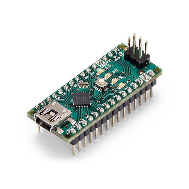
The Arduino Nano is a small, complete, and breadboard-friendly board based on the ATmega328 (Arduino Nano 3.x). It has more or less the same functionality of the Arduino Duemilanove but in a different package. It lacks only a DC power jack and works with a Mini-B USB cable instead of a standard one.
Specifications
Microcontroller
ATmega328
Operating Voltage (logic level)
5 V
Input Voltage (recommended)
7-12 V
Input Voltage (limits)
6-20 V
Digital I/O Pins
14 (of which 6 provide PWM output)
Analog Input Pins
8
DC Current per I/O Pin
40 mA
Flash Memory
16 KB (ATmega168) or 32 KB (ATmega328) of which 2 KB used by bootloader
SRAM
1 KB (ATmega168) or 2 KB (ATmega328)
EEPROM
512 bytes (ATmega168) or 1 KB (ATmega328)
Clock Speed
16 MHz
Dimensions
0.73 x 1.70' (18 x 45 mm)
Power
The Arduino Nano can be powered via the Mini-B USB connection, 6-20 V unregulated external power supply (pin 30), or 5 V regulated external power supply (pin 27). The power source is automatically selected to the highest voltage source.
Memory
The ATmega168 has 16 KB of flash memory for storing code (of which 2 KB is used for the bootloader), 1 KB of SRAM and 512 bytes of EEPROM
The ATmega328 has 32 KB of flash memory for storing code, (also with 2 KB used for the bootloader), 2 KB of SRAM and 1 KB of EEPROM.
Input and Output
Each of the 14 digital pins on the Nano can be used as an input or output, using pinMode(), digitalWrite(), and digitalRead() functions. They operate at 5 V.
Each pin can provide or receive a maximum of 40 mA and has an internal pull-up resistor (disconnected by default) of 20-50 kOhms.
Communication
The Arduino Nano has a number of facilities for communicating with a computer, another Arduino, or other microcontrollers.
The ATmega168 and ATmega328 provide UART TTL (5V) serial communication, which is available on digital pins 0 (RX) and 1 (TX). An FTDI FT232RL on the board channels this serial communication over USB and the FTDI drivers (included with the Arduino software) provide a virtual com port to software on the computer.
The Arduino software includes a serial monitor which allows simple textual data to be sent to and from the Arduino board. The RX and TX LEDs on the board will flash when data is being transmitted via the FTDI chip and USB connection to the computer (but not for serial communication on pins 0 and 1).
A SoftwareSerial library allows for serial communication on any of the Nano's digital pins.
Programming
The Arduino Nano can be programmed with the Arduino software (download).
The ATmega168 or ATmega328 on the Arduino Nano comes with a bootloader that allows you to upload new code to it without the use of an external hardware programmer. It communicates using the original STK500 protocol (reference, C header files).
You can also bypass the bootloader and program the microcontroller through the ICSP (In-Circuit Serial Programming) header using Arduino ISP or similar; see these instructions for details.
Automatic (Software) Reset
Rather than requiring a physical press of the reset button before an upload, the Arduino Nano is designed in a way that allows it to be reset by software running on a connected computer.
One of the hardware flow control lines (DTR) of theFT232RL is connected to the reset line of the ATmega168 or ATmega328 via a 100 nF capacitor. When this line is asserted (taken low), the reset line drops long enough to reset the chip.
The Arduino software uses this capability to allow you to upload code by simply pressing the upload button in the Arduino environment. This means that the bootloader can have a shorter timeout, as the lowering of DTR can be well-coordinated with the start of the upload.
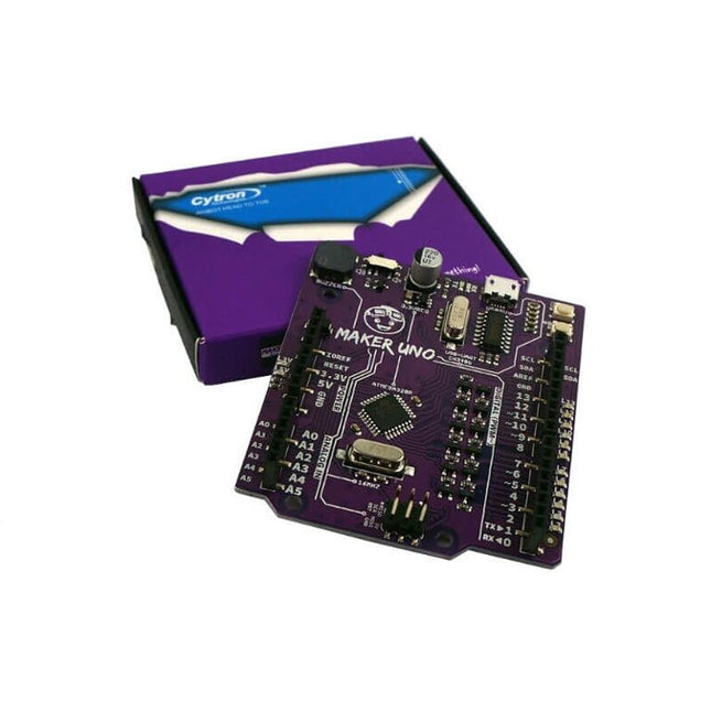
Features Piezo Buzzer: Acts as a simple audio output Micro USB Port Programmable Button 12 x LED: Provides visual output on board Specifications Microcontroller ATmega328P Programming IDE Arduino IDE Operating Voltage 5 V Digital I/O 20 PWM 6 Analog Input 6 (10-bit) UART 1 SPI 1 I2C 1 External Interrupt 2 Flash Memory 32 KB SRAM 2 KB EEPROM / Data Flash 1 KB Clock Speed 16 MHz DC Current I/O Pin 20 mA Power Supply USB only DC Current for 5 V USB Source DC Current for 3.3 V 500 mA USB to Serial Chip CH340G Programmable LED 12 at digital Pin 2 to 13 Programmable Push Button 1 at digital Pin 2 Piezo Buzzer 1 at digital Pin 8 Arduino vs Maker Uno
The Arduino Nano Every is an evolution of the traditional Arduino Nano board but features a lot more powerful processor, the ATMega4809. This will allow you to make larger programs than with the Arduino Uno (it has 50% more program memory), and with a lot more variables (the RAM is 200% bigger). An Improved Arduino Nano If you used Arduino Nano in your projects in the past, the Nano Every is a pin-equivalent substitute. The main differences are a better processor and a micro-USB connector. The board comes in two options: with or without headers, allowing you to embed the Nano Every inside any kind of invention, including wearables. The board comes with tessellated connectors and no components on the B-side. These features allow you to solder the board directly onto your own design, minimizing the height of your whole prototype. Oh, and did we mention the improved price? Thanks to a revised manufacturing process, the Arduino Nano Every costs a fraction of the original Nano … what are you waiting for? Upgrade now! Microcontroller ATMega4809 Operating Voltage 5 V Input Voltage 7 V - 21 V Analog Input Pins 8 Analog Output Pins Only through PWM External Interrupts all digital pins DC Current per I/O Pin 20 mA DC Current for 3.3 V Pin 50 mA Flash Memory 48 KB SRAM 6 KB EEPROM 256 Byte Clock Speed 20 MHz LED_Builtin 13 UART 1 SPI 1 I2C 1 PWM Pins 5 USB Uses the ATSAMD11D14A Length 45 mm Width 18 mm Weight 5 g
The RedBoard Artemis has the improved power conditioning and USB to serial that we've refined over the years on our RedBoard line of products. A modern USB-C connector makes programming easy. A Qwiic connector makes I²C easy. The RedBoard Artemis is fully compatible with SparkFun's Arduino core and can be programmed easily under the Arduino IDE. We've exposed the JTAG connector for more advanced users who prefer to use professional tools' power and speed. We've added a digital MEMS microphone for folks wanting to experiment with always-on voice commands with TensorFlow and machine learning. We've even added a convenient jumper to measure current consumption for low power testing. With 1MB flash and 384k RAM, you'll have plenty of room for your sketches. The on-board Artemis module runs at 48MHz with a 96MHz turbo mode available and with Bluetooth to boot! Features Arduino Uno R3 Footprint 1M Flash / 384k RAM 48MHz / 96MHz turbo available 24 GPIO - all interrupt capable 21 PWM channels Built-in BLE radio 10 ADC channels with 14-bit precision 2 UARTs 6 I²C buses 4 SPI buses PDM Interface I²S Interface Qwiic Connector
The Uno differs from all preceding boards in that it does not use the FTDI USB-to-serial driver chip. Additional features coming with the R3 version are: ATmega16U2 instead of 8U2 as a USB-to-Serial converter. 1.0 pinout: added SDA and SCL pins for TWI communication placed near to the AREF pin and two other new pins placed near to the RESET pin, the IOREF that allow the shields to adapt to the voltage provided from the board and the second one is a not connected pin, that is reserved for future purposes. stronger RESET circuit. Microcontroller ATmega328P Operating Voltage 5 V Input Voltage 7 V - 12 V Digital I/O Pins 14 PWM Pins 6 Analog Input Pins 8 DC Current per I/O Pin 20 mA DC Current for 3.3 V Pin 50 mA Flash Memory 32 KB (ATmega328P) of which 0.5 KB used by bootloader SRAM 2 KB EEPROM 1 KB Clock Speed 16 MHz LED_Builtin 13 Length 68.6 mm Width 53.4 mm Weight 25 g
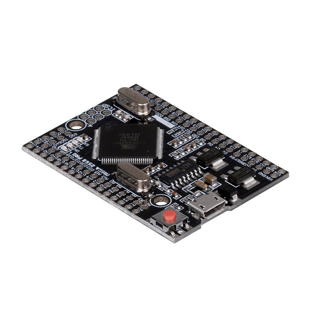
This JOY-iT microcontroller board opens the world of programming to you and offers you the same computing power as the Mega 2560, but with a smaller foot-print. It also has many more connectors than comparable boards (Arduino Uno). It is powered by the Arduino IDE and power can be supplied either via the USB port or the VIN pins. This allows you to use it safely with many other devices, e.g. desktop PC. Therefore the Mega 2560 Pro is highly integrable.
Features
Microcontroller
ATmega2560 - 16AU
Storage
Flash 256 KB, SRAM 8 KB, EEPRom 4 KB
Amount of Pins:Digital I/OPWM OutputAnalog Input
541516
Compatible with
Arduino, Desktop PCs, etc.
Special features
USB Port or Power Pins for power supply
Interface converter
Micro USB to USB UART
Size
55 x 38 mm
Items delivered
JOY-iT Mega 2560 Pro with Pins
Further Specifications
Input Voltage
7 - 9 Volt on Vin, 5 Volt on mUSB
Logic level
5 Volt
Output current
800 mA
Voltage regulator
LDO (for up to 12 V peak)
Frequency
16 MHz (12 MHz are possible for data exchange)
Downloads
Manual
The SparkFun RedBoard Qwiic is an Arduino-compatible board that combines features of different Arduinos with the Qwiic Connect System.
Features
ATmega328 microcontroller with Optiboot Bootloader
R3 Shield Compatible
CH340C Serial-USB Converter
3.3 V to 5 V Voltage Level Jumper
A4 / A5 Jumpers
AP2112 Voltage Regulator
ISP Header
Input voltage: 7 V - 15 V
1 Qwiic Connector
16 MHz Clock Speed
32 k Flash Memory
All SMD Construction
Improved Reset Button
The Arduino Nano 33 BLE Rev2 stands at the forefront of innovation, leveraging the advanced capabilities of the nRF52840 microcontroller. This 32-bit Arm Cortex-M4 CPU, operating at an impressive 64 MHz, empowers developers for a wide range of projects. The added compatibility with MicroPython enhances the board's flexibility, making it accessible to a broader community of developers.
The standout feature of this development board is its Bluetooth Low Energy (Bluetooth LE) capability, enabling effortless communication with other Bluetooth LE-enabled devices. This opens up a realm of possibilities for creators, allowing them to seamlessly share data and integrate their projects with a wide array of connected technologies.
Designed with versatility in mind, the Nano 33 BLE Rev2 is equipped with a built-in 9-axis Inertial Measurement Unit (IMU). This IMU is a game-changer, offering precise measurements of position, direction, and acceleration. Whether you're developing wearables or devices that demand real-time motion tracking, the onboard IMU ensures unparalleled accuracy and reliability.
In essence, the Nano 33 BLE Rev2 strikes the perfect balance between size and features, making it the ultimate choice for crafting wearable devices seamlessly connected to your smartphone. Whether you're a seasoned developer or a hobbyist embarking on a new adventure in connected technology, this development board opens up a world of possibilities for innovation and creativity. Elevate your projects with the power and flexibility of the Nano 33 BLE Rev2.
Specifications
Microcontroller
nRF52840
USB connector
Micro USB
Pins
Built-in LED Pins
13
Digital I/O Pins
14
Analog Input Pins
8
PWM Pins
All digital pins (4 at once)
External interrupts
All digital pins
Connectivity
Bluetooth
u-blox NINA-B306
Sensors
IMU
BMI270 (3-axis accelerometer + 3-axis gyroscope) + BMM150 (3-axis Magnetometer)
Communication
UART
RX/TX
I²C
A4 (SDA), A5 (SCL)
SPI
D11 (COPI), D12 (CIPO), D13 (SCK). Use any GPIO for Chip Select (CS)
Power
I/O Voltage
3.3 V
Input Voltage (nominal)
5-18 V
DC Current per I/O Pin
10 mA
Clock Speed
Processor
nRF52840 64 MHz
Memory
nRF52840
256 KB SRAM, 1 MB flash
Dimensions
18 x 45 mm
Downloads
Datasheet
Schematics
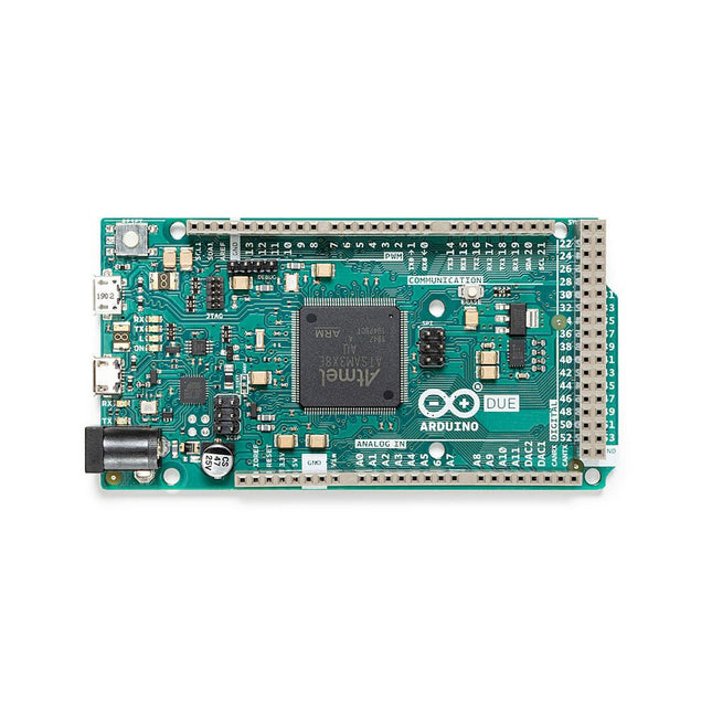
The board contains everything needed to support the microcontroller; simply connect it to a computer with a micro-USB cable or power it with an AC-to-DC adapter or battery to get started. The Due is compatible with all Arduino shields that work at 3.3V and are compliant with the 1.0 Arduino pinout.
The Due follows the 1.0 pinout:
TWI: SDA and SCL pins that are near to the AREF pin.
IOREF: allows an attached shield with the proper configuration to adapt to the voltage provided by the board. This enables shield compatibility with a 3.3V board like the Due and AVR-based boards which operate at 5V.
An unconnected pin, reserved for future use.
Specifications
Operating Voltage
3.3 V
Input Voltage
7-12 V
Digital I/O
54
Analog Input Pins
12
Analog Output Pins
2 (DAC)
Total DC Output Current on all I/O Lines
130 mA
DC Current per I/O Pin
20 mA
DC Current for 3.3 V Pin
800 mA
DC Current for 5 V Pin
800 mA
Flash Memory
512 KB all available for the user applications
SRAM
96 KB
Clock Speed
84 MHz
Length
101.52 mm
Width
53.3 mm
Weight
36 g
Please note: Unlike most Arduino boards, the Arduino Due board runs at 3.3V. The maximum voltage that the I/O pins can tolerate is 3.3V. Applying voltages higher than 3.3V to any I/O pin could damage the board.
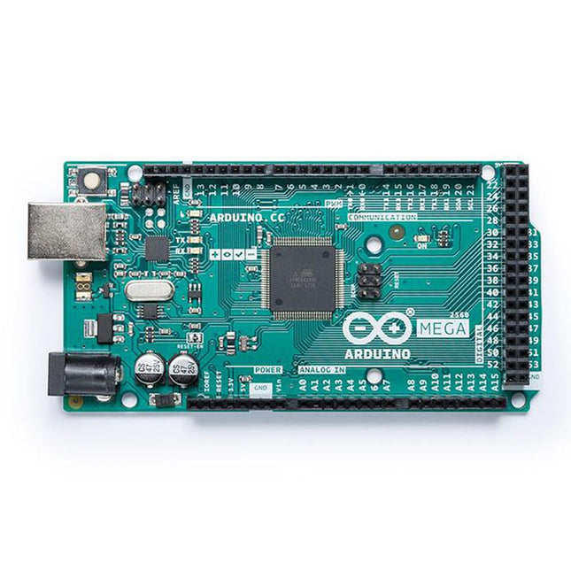
It contains everything needed to support the microcontroller; simply connect it to a computer with a USB cable or power it with an AC-to-DC adapter or battery to get started. The Mega 2560 board is compatible with most shields designed for the Uno and the former boards Duemilanove or Diecimila. Operating Voltage 5 V Input Voltage 7 V - 12 V Digital I/O 54 Analog Input Pins 16 DC Current per I/O Pin 20 mA DC Current for 3.3 V Pin 50 mA Flash Memory 256 KB of which 8 KB used by the bootloader SRAM 8 KB EEPROM 4 KB Clock Speed 16MHz LED_Builtin 13 Length 101.52 mm Width 53.3 mm Weight 37 g For more information, check out the Getting Started Guide from Arduino.
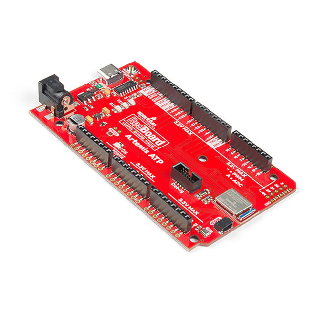
What's with the silkscreen labels? They're all over the place. We decided to label the pins as they are assigned on the Apollo3 IC itself. This makes finding the pin with the function you desire a lot easier. Have a look at the full pin map from the Apollo3 datasheet. If you really need to test out the 4-bit SPI functionality of the Artemis, you're going to need to access pins 4, 22, 23, and 26. Need to try out the differential ADC port 1? Pins 14 and 15. The RedBoard Artemis ATP will allow you to flex the impressive capabilities of the Artemis module.
The RedBoard Artemis ATP has the improved power conditioning and USB to serial that we've refined over the years on our RedBoard line of products. A modern USB-C connector makes programming easy. A Qwiic connector makes I²C easy. The ATP is fully compatible with SparkFun's Arduino core and can be programmed easily under the Arduino IDE. We've exposed the JTAG connector for more advanced users who prefer to use the power and speed of professional tools. If you need a lot of a GPIO with a simple program, ready to go to the market module, the ATP is the fix you need. We've added a digital MEMS microphone for folks wanting to experiment with always-on voice commands with TensorFlow and machine learning. We've even added a convenient jumper to measure current consumption for low power testing.
With 1 MB flash and 384k RAM, you'll have plenty of room for your sketches. The Artemis module runs at 48 MHz with a 96 MHz turbo mode available and with Bluetooth to boot!
Features
Arduino Mega Footprint
1M Flash / 384k RAM
48MHz / 96MHz turbo available
6uA/MHz (operates less than 5mW at full operation)
48 GPIO - all interrupt capable
31 PWM channels
Built-in BLE radio
10 ADC channels with 14-bit precision with up to 2.67 million samples per second effective continuous, multi-slot sampling rate
2 channel differential ADC
2 UARTs
6 I²C buses
6 SPI buses
2/4/8-bit SPI bus
PDM interface
I²S Interface
Secure 'Smart Card' interface
Qwiic Connector
Bluno is the first of its kind in integrating Bluetooth 4.0 (BLE) module into Arduino Uno, making it an ideal prototyping platform for both software and hardware developers to go BLE. You will be able to develop your own smart bracelet, smart pedometer, and more. Through the low-power Bluetooth 4.0 technology, real-time low energy communication can be made really easy.
Bluno integrates a TI CC2540 BT 4.0 chip with the Arduino UNno. It allows wireless programming via BLE, supports Bluetooth HID, AT command to config BLE and you can upgrade BLE firmware easily. Bluno is also compatible with all 'Arduino Uno' pins which means any project made with Uno can directly go wireless!
Specifications
On-board BLE chip: TI CC2540
Wireless Programming via BLE
Support Bluetooth HID
Support AT command to config the BLE
Transparent communication through Serial
Upgrade BLE firmware easily
DC Supply: USB Powered or External 7~12 V DC
Microcontroller: Atmega328
Bootloader: Arduino Uno ( disconnect any BLE device before uploading a new sketch )
Compatible with the Arduino Uno pin mapping
Size: 60 x 53 mm(2.36 x 2.08')
Weight: 30 g
The board's main processor is a low-power ARM Cortex-M0 32-bit SAMD21, like in the other boards within the Arduino MKR family. The WiFi and Bluetooth connectivity is performed with a module from u-blox, the NINA-W10, a low-power chipset operating in the 2.4 GHz range. On top of that, secure communication is ensured through the Microchip ECC508 crypto chip. Besides that, you can find a battery charger, and an RGB LED on-board.
Official Arduino WiFi Library
You can get your board to connect to any kind of existing WiFi network, or use it to create your own Arduino Access Point. The specific set of examples we provide for the MKR WiFi 1010 can be consulted at the WiFiNINA library reference page.
Compatible with other Cloud Services
It is also possible to connect your board to different Cloud services, Arduino's own among others. Here are some examples of how to get the MKR WiFi 1010 to connect to:
Blynk: a simple project from the Arduino community connecting to Blynk to operate your board from a phone with little code
IFTTT: in-depth case of building a smart plug connected to IFTTT
AWS IoT Core: Arduino made this example on how to connect to Amazon Web Services
Azure: visit this GitHub repository explaining how to connect a temperature sensor to Azure's Cloud
Firebase: you want to connect to Google's Firebase, this Arduino library will show you how
Specifications
Microcontroller
SAMD21 Cortex-M0+ 32bit low power ARM MCU
Radio Module
u-blox NINA-W102
Power Supply
5 V
Secure Element
ATECC508
Supported Battery
Li-Po Single Cell, 3.7 V, 1024 mAh Minimum
Operating Voltage
3.3 V
Digital I/O Pins
8
PWM Pins
13
UART
1
SPI
1
I2C
1
Analog Input Pins
7
Analog Output Pins
1
External Interrupts
10
Flash Memory
256 KB
SRAM
32 KB
EEPROM
no
Clock Speed
32.768 kHz, 48 MHz
LED_Builtin
6
USB
Full-Speed USB Device and embedded Host
Length
61.5 mm
Width
25 mm
Weight
32 g
The Arduino Nano 33 BLE Sense Rev2 with headers is Arduino’s 3.3 V AI enabled board in the smallest available form factor with a set of sensors that will allow you without any external hardware to start programming your next project, right away.
With the Arduino Nano 33 BLE Sense Rev2, you can:
Build wearable devices that using AI can recognize movements.
Build a room temperature monitoring device that can suggest or modify changes in the thermostat.
Build a gesture or voice recognition device using the microphone or the gesture sensor together with the AI capabilities of the board.
Differences between Rev1 and Rev2
Replacement of IMU from LSM9DS1 (9 axis) for a combination of two IMUs (BMI270 – 6 axis IMU and BMM150 – 3 axis IMU)
Replacement of temperature and humidity sensor from HTS221 for HS3003
Replacement of microphone from MP34DT05 to MP34DT06JTR
Replacement of power supply MPM3610 for MP2322
Addition of VUSB soldering jumper on the top side of the board
New test point for USB, SWDIO and SWCLK
Specifications
Microcontroller
nRF52840 (datasheet)
Operating Voltage
3.3 V
Input Voltage (limit)
21 V
DC Current per I/O Pin
15 mA
Clock Speed
64 MHz
CPU Flash Memory
1 MB (nRF52840)
SRAM
256 KB (nRF52840)
EEPROM
None
Digital Input / Output Pins
14
PWM Pins
All digital pins
UART
1
SPI
1
I²C
1
Analog Input Pins
8 (ADC 12 bit 200 k samples)
Analog Output Pins
Only through PWM (no DAC)
External Interrupts
All digital pins
LED_BUILTIN
13
USB
Native in the nRF52840 Processor
IMU
BMI270 (datasheet) and BMM150 (datasheet)
Microphone
MP34DT06JTR (datasheet)
Gesture, light, proximity, color
APDS9960 (datasheet)
Barometric pressure
LPS22HB (datasheet)
Temperature, humidity
HS3003 (datasheet)
Downloads
Datasheet
Schematics
The ATmega328 Uno Development Board (Arduino Uno compatible) is a microcontroller board based on the ATmega328.
It has 14 digital input/output pins (of which 6 can be used as PWM outputs), 6 analogue inputs, a 16 MHz ceramic resonator, a USB connection, a power jack, an ICSP header and a reset button.
It contains everything needed to support the microcontroller; connect it to a computer with a USB cable or power it with a AC-to-DC adapter or battery to get started.
Specifications
Microcontroller
ATmega328
Operating voltage
5 V DC
Input voltage (recommended)
7-12 V DC
Input voltage (limits)
6-20 V DC
Digital I/O pins
14 (of which 6 provide PWM output)
Analogue input pins
6
SRAM
2 kB (ATmega328)
EEPROM
1 kB (ATmega328)
Flash memory
32 kB (ATmega328) of which 0.5 kB used by bootloader
Clock speed
16 MHz
Downloads
Manual
The Portenta C33 is a powerful System-on-Module designed for low-cost Internet of Things (IoT) applications. Based on the R7FA6M5BH2CBG microcontroller from Renesas, this board shares the same form factor as the Portenta H7 and it is backward compatible with it, making it fully compatible with all Portenta family shields and carriers through its high-density connectors.
As a low-cost device, the Portenta C33 is an excellent choice for developers looking to create IoT devices and applications on a budget. Whether you're building a smart home device or a connected industrial sensor, the Portenta C33 provides the processing power and connectivity options you need to get the job done.
Quickly deploying AI-powered projects becomes quick and easy with Portenta C33, by leveraging a vast array of ready-to-use software libraries and Arduino sketches available, as well as widgets that display data in real time on Arduino IoT Cloud-based dashboards.
Features
Ideal for low-cost IoT applications with Wi-Fi/Bluetooth LE connectivity
Supports MicroPython and other high-level programming languages
Offers industrial-grade security at the hardware level and secure OTA firmware updates
Leverages ready-to-use software libraries and Arduino sketches
Perfect to monitor and display real-time data on Arduino IoT Cloud widget-based dashboards
Compatible with Arduino Portenta and MKR families
Features castellated pins for automatic assembly lines
Cost Effective Performance
Reliable, secure and with computational power worthy of its range, Portenta C33 was designed to provide big and small companies in every field with the opportunity to access IoT and benefit from higher efficiency levels and automation.
Applications
Portenta C33 brings more applications than ever within users’ reach, from enabling quick plug-and-play prototyping to providing a cost-effective solution for industrial-scale projects.
Industrial IoT gateway
Machine monitoring to track OEE/OPE
Inline quality control and assurance
Energy consumption monitoring
Appliances control system
Ready-to-use IoT prototyping solution
Specifications
Microcontroller
Renesas R7FA6M5BH2CBG ARM Cortex-M33:
ARM Cortex-M33 core up to 200 MHz
512 kB onboard SRAM
2 MB onboard Flash
Arm TrustZone
Secure Crypto Engine 9
External Memories
16 MB QSPI Flash
USB-C
USB-C High Speed
Connectivity
100 MB Ethernet interface (PHY)
Wi-Fi
Bluetooth Low Energy
Interfaces
CAN
SD Card
ADC
GPIO
SPI
I²S
I²C
JTAG/SWD
Security
NXP SE050C2 Secure Element
Operating Temperatures
-40 to +85°C (-40 to 185°F)
Dimensions
66,04 x 25,40 mm
Downloads
Datasheet
Schematics
The Arduino Pro Portenta Max Carrier transforms Portenta modules into single-board computers or reference designs that enable edge AI for high-performance industrial, building automation and robotics applications. Thanks to dedicated high-density connectors, it can be paired with Portenta X8 or H7, allowing you to easily prototype and deploy your industrial projects. This Arduino Pro carrier further augments Portenta connectivity options with Fieldbus, LoRa, Cat-M1 and NB-IoT.
Among the many available plug-and-play connectors there are Ethernet, USB-A, audio jacks, microSD, mini-PCIe, FD-CAN and Serial RS232/422/485.
Max Carrier can be powered via external supply (6-36 V) or battery via the onboard 18650 Li-ion battery connector with 3.7 V battery charger.
Features
Easily prototype industrial applications and minimize time to market
A powerful carrier exposing Portenta peripherals (e.g. CAN, RS232/422/485, USB, mPCIe)
Multiple connectivity options (Ethernet, LoRa, CAT-M1, NB-IoT)
MicroSD for data logging operations
Integrated audio jacks (line-in, line-out, mic-in)
Standalone when battery powered
Onboard JTAG debugger via micro-USB (with Portenta H7 only)
Specifications
Connectors
High-Density connectors compatible with Portenta products2x USB-A female connectors1x Gigabit Ethernet connector (RJ45)1x FD-Can on RJ111x mPCIe1x Serial RS232/422/485 on RJ12
Audio
3x audio jacks: stereo line-in/line-out, mic-inSpeaker connector
Memory
Micro SD
Wireless modules
Murata CMWX1ZZABZ-078 LoRaSARA-R412M-02B (Cat.M1/NB-IoT)
Operating temperatures
-40 °C to +85 °C (-40° F to 185 °F)
Debugging
Onboard JLink OB / Blackmagic probe
Power/battery
Power Jack for external supply (6-36 V)On-board 18650 Li-ion battery connector with battery charger (3.7 V)
Dimensions
101.6 x 101.6 mm (4.0 x 4.0')
Downloads
Datasheet
Schematics