Products
-
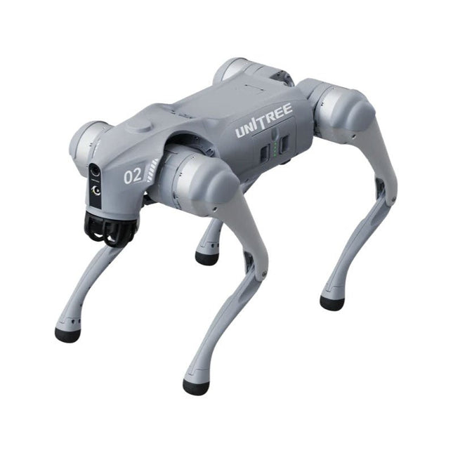
Unitree Unitree Go2 Edu Plus Quadruped Robot
Temporary Delay in the Delivery of Unitree Robots Like many other suppliers, we are currently experiencing delays in the delivery of Unitree robots. A shipment from our supplier is currently held in customs, which has unfortunately led to later-than-planned deliveries for previously placed orders. We are actively working with our supplier to resolve this issue and expect more clarity soon, but at this time, we cannot provide any guarantees. Additionally, a new shipment is already on its way, though it will take some time to arrive. Since other suppliers are facing similar challenges, switching to a different provider is unlikely to result in a faster solution. Our top priority remains fulfilling existing orders. If you have any questions or would like to update your order, please do not hesitate to contact our customer service team. We will keep you informed of any further developments. Unitree Go2 series consists of quadruped robots for the research & development of autonomous systems in the fields of human-robot interaction (HRI), SLAM & transportation. Due to the four legs, as well as the 12DOF, this robot can handle a variety of different terrains. The Go2 comes with a perfected drive & power management system, which enables a speed (depending on the version) of up to 3.7 m/s or 11.88 km/h with an operating time of up to 4 hours. Furthermore, the motors have a torque of 45 N.m at the body/thighs and at the knees, which also allow jumps or backflips. Features Super Recognition System: 4D LIDAR L1 Max Running Speed: approx. 5 m/s Peak Joint Torque: approx. 45 N.m Wireless Module: WiFi 6/Bluetooth/4G Ultra-long battery Endurance: approx. 2-4 h (long battery life measured in real life) Intelligent Side-follow System: ISS 2.0 Specifications Tracking module: Remote-controlled or automatic tracking Front camera: Image tansmission Resolution 1280x720, FOV 120°, Ultra wide angle lens deliver rich clarity Front lamp: Brightly lights the way ahead 4D LiDAR L1: 360°x90° omnidirectional ultra-wide-angle scanning allows automatic avoidance with small blind spot and stable operation 12 knee joint motors: Strong and powerful, Beautiful and simple, Brandy new visual experience Intercom microphone: Effective communication with no scenario restrictions Self-retracting strap: Easy to carry and load things More stable, more powerful with advanced devices: 3D LiDAR, 4G ESIM Card, WiFi 6 with Dual-band, Bluetooth 5.2 for stable connection and remote control Powerful Computing Core: Motion controller, High-performance ARM processor, Improved Al algorithm processor, External ORIN NX/NANO Smart battery: Standard 8000 mAh battery, Long-endurance 15000 mAh battery, Protection from over-temp, overcharge and short-circuit Speaker for music play: Listen to music as your pleasure Unitree Go2 Variants The Go2 impresses not only with its technical capabilities, but also with a modern and slim design that gives it a futuristic look and makes it a real eye-catcher. The Go2 Air is specially designed for demos and presentations. With its basic features, it offers a solid basis for demonstrating the movement capabilities and functionality of a four-legged robot. Important: The Go2 Air is delivered without a controller. This can be purchased optionally. With a powerful 8-core high-performance CPU, the Pro and Edu offer impressive computing power required for complex tasks and demanding calculations. This enables faster and more efficient data processing and makes the Pro and Edu a reliable partner for your projects. From the Edu version onwards, the Go2 is programmable and opens up endless possibilities for developing and researching your own robotics applications. The Go2 is also able to handle a step height of up to 14 cm. This makes it an ideal tool for research, education and entry into the world of robotics. The Go2 Edu comes with a remote controller that gives you easy and intuitive control. You also get a docking station with impressive computing power of 100 TOPS, which is equipped with powerful AI algorithms and offers you technical support. Go2 Edu is equipped with a powerful 15000 mAh battery that gives it an impressive runtime of up to 4 hours. This long operating time allows the robot to carry out longer exploration missions and complete demanding tasks. Model Comparison Air Pro Edu/Edu Plus Dimensions (standing) 70 x 31 x 40 cm 70 x 31 x 40 cm 70 x 31 x 40 cm Dimensions (crouching) 76 x 31 x 20 cm 76 x 31 x 20 cm 76 x 31 x 20 cm Material Aluminium alloy + High strength engineering plastic Aluminium alloy + High strength engineering plastic Aluminium alloy + High strength engineering plastic Weight (with battery) about 15 kg about 15 kg about 15 kg Voltage 28~33.6 V 28~33.6 V 28~33.6 V Peaking capacity about 3000 W about 3000 W about 3000 W Payload ≈7 kg (MAX ~ 10 kg) ≈8 kg (MAX ~ 10 kg) ≈8 kg (MAX ~ 12 kg) Speed 0~2.5 m/s 0~3.5 m/s 0~3.7 m/s (MAX ~ 5 m/s) Max Climb Drop Height about 15 cm about 16 cm about 16 cm Max Climb Angle 30° 40° 40° Basic Computing Power N/A 8-core High-performance CPU 8-core High-performance CPU Aluminum knee joint motor 12 set 12 set 12 set Intra-joint circuit (knee) ✓ ✓ ✓ Joint Heat Pipe Cooler ✓ ✓ ✓ Range of Motion Body: −48~48° Body: −48~48° Body: −48~48° Thigh: −200°~90° Thigh: −200°~90° Thigh: −200°~90° Shank: −156°~−48° Shank: −156°~−48° Shank: −156°~−48° Max Torque N/A about 45 N.m about 45 N.m Super-wide-angle 3D LiDAR ✓ ✓ ✓ Wireless Vector Positioning Tracking Module N/A ✓ ✓ HD Wide-angle Camera ✓ ✓ ✓ Foot-end force sensor N/A N/A ✓ Basic Action ✓ ✓ ✓ Auto-scaling strap N/A ✓ N/A Upgraded Intelligent OTA ✓ ✓ ✓ RTT 2.0 Image Transmission ✓ ✓ ✓ App Basic Remote Control ✓ ✓ ✓ App Data Viewing ✓ ✓ ✓ App Graphical Programme ✓ ✓ ✓ Front Lamp (3 W) ✓ ✓ ✓ WiFi 6 with Dual-band ✓ ✓ ✓ Bluetooth 5.2/4.2/2.1 ✓ ✓ ✓ 4G Module N/A CN/GB CN/GB Voice Function N/A ✓ ✓ Music Playback N/A ✓ ✓ ISS 2.0 Intelligent side-follow system N/A ✓ ✓ Intelligent detection and avoidance ✓ ✓ ✓ Secondary development N/A N/A ✓ Manual controller Optional Optional ✓ High computing power module N/A N/A Edu: 40 TOPS computing power Edu Plus: 100 TOPS computing power NVIDIA Jetson Orin (optional) Smart Battery Standard (8000 mAh) Standard (8000 mAh) Long endurance (15000 mAh) Battery Life 1-2 h 1-2 h 2-4 h Charger Standard (33.6 V, 3.5 A) Standard (33.6 V, 3.5 A) Fast charge (33.6 V, 9 A) Included 1x Unitree Go2 Edu Plus 1x Unitree Go2 Remote Controller 1x Unitree Go2 Battery (15000 mAh) 1x Unitree Docking station with 100 TOPS computing power Downloads Documentation iOS/Android apps GitHub
€ 14.999,00
Best Price
-

Unitree Unitree Go2 Edu Quadruped Robot
Temporary Delay in the Delivery of Unitree Robots Like many other suppliers, we are currently experiencing delays in the delivery of Unitree robots. A shipment from our supplier is currently held in customs, which has unfortunately led to later-than-planned deliveries for previously placed orders. We are actively working with our supplier to resolve this issue and expect more clarity soon, but at this time, we cannot provide any guarantees. Additionally, a new shipment is already on its way, though it will take some time to arrive. Since other suppliers are facing similar challenges, switching to a different provider is unlikely to result in a faster solution. Our top priority remains fulfilling existing orders. If you have any questions or would like to update your order, please do not hesitate to contact our customer service team. We will keep you informed of any further developments. Unitree Go2 series consists of quadruped robots for the research & development of autonomous systems in the fields of human-robot interaction (HRI), SLAM & transportation. Due to the four legs, as well as the 12DOF, this robot can handle a variety of different terrains. The Go2 comes with a perfected drive & power management system, which enables a speed (depending on the version) of up to 3.7 m/s or 11.88 km/h with an operating time of up to 4 hours. Furthermore, the motors have a torque of 45 N.m at the body/thighs and at the knees, which also allow jumps or backflips. Features Super Recognition System: 4D LIDAR L1 Max Running Speed: approx. 5 m/s Peak Joint Torque: approx. 45 N.m Wireless Module: WiFi 6/Bluetooth/4G Ultra-long battery Endurance: approx. 2-4 h (long battery life measured in real life) Intelligent Side-follow System: ISS 2.0 Specifications Tracking module: Remote-controlled or automatic tracking Front camera: Image tansmission Resolution 1280x720, FOV 120°, Ultra wide angle lens deliver rich clarity Front lamp: Brightly lights the way ahead 4D LiDAR L1: 360°x90° omnidirectional ultra-wide-angle scanning allows automatic avoidance with small blind spot and stable operation 12 knee joint motors: Strong and powerful, Beautiful and simple, Brandy new visual experience Intercom microphone: Effective communication with no scenario restrictions Self-retracting strap: Easy to carry and load things More stable, more powerful with advanced devices: 3D LiDAR, 4G ESIM Card, WiFi 6 with Dual-band, Bluetooth 5.2 for stable connection and remote control Powerful Computing Core: Motion controller, High-performance ARM processor, Improved Al algorithm processor, External ORIN NX/NANO Smart battery: Standard 8000 mAh battery, Long-endurance 15000 mAh battery, Protection from over-temp, overcharge and short-circuit Speaker for music play: Listen to music as your pleasure Unitree Go2 Variants The Go2 impresses not only with its technical capabilities, but also with a modern and slim design that gives it a futuristic look and makes it a real eye-catcher. The Go2 Air is specially designed for demos and presentations. With its basic features, it offers a solid basis for demonstrating the movement capabilities and functionality of a four-legged robot. Important: The Go2 Air is delivered without a controller. This can be purchased optionally. With a powerful 8-core high-performance CPU, the Pro and Edu offer impressive computing power required for complex tasks and demanding calculations. This enables faster and more efficient data processing and makes the Pro and Edu a reliable partner for your projects. From the Edu version onwards, the Go2 is programmable and opens up endless possibilities for developing and researching your own robotics applications. The Go2 is also able to handle a step height of up to 14 cm. This makes it an ideal tool for research, education and entry into the world of robotics. The Go2 Edu comes with a remote controller that gives you easy and intuitive control. You also get a docking station with impressive computing power of 100 TOPS, which is equipped with powerful AI algorithms and offers you technical support. Go2 Edu is equipped with a powerful 15000 mAh battery that gives it an impressive runtime of up to 4 hours. This long operating time allows the robot to carry out longer exploration missions and complete demanding tasks. Model Comparison Air Pro Edu/Edu Plus Dimensions (standing) 70 x 31 x 40 cm 70 x 31 x 40 cm 70 x 31 x 40 cm Dimensions (crouching) 76 x 31 x 20 cm 76 x 31 x 20 cm 76 x 31 x 20 cm Material Aluminium alloy + High strength engineering plastic Aluminium alloy + High strength engineering plastic Aluminium alloy + High strength engineering plastic Weight (with battery) about 15 kg about 15 kg about 15 kg Voltage 28~33.6 V 28~33.6 V 28~33.6 V Peaking capacity about 3000 W about 3000 W about 3000 W Payload ≈7 kg (MAX ~ 10 kg) ≈8 kg (MAX ~ 10 kg) ≈8 kg (MAX ~ 12 kg) Speed 0~2.5 m/s 0~3.5 m/s 0~3.7 m/s (MAX ~ 5 m/s) Max Climb Drop Height about 15 cm about 16 cm about 16 cm Max Climb Angle 30° 40° 40° Basic Computing Power N/A 8-core High-performance CPU 8-core High-performance CPU Aluminum knee joint motor 12 set 12 set 12 set Intra-joint circuit (knee) ✓ ✓ ✓ Joint Heat Pipe Cooler ✓ ✓ ✓ Range of Motion Body: −48~48° Body: −48~48° Body: −48~48° Thigh: −200°~90° Thigh: −200°~90° Thigh: −200°~90° Shank: −156°~−48° Shank: −156°~−48° Shank: −156°~−48° Max Torque N/A about 45 N.m about 45 N.m Super-wide-angle 3D LiDAR ✓ ✓ ✓ Wireless Vector Positioning Tracking Module N/A ✓ ✓ HD Wide-angle Camera ✓ ✓ ✓ Foot-end force sensor N/A N/A ✓ Basic Action ✓ ✓ ✓ Auto-scaling strap N/A ✓ N/A Upgraded Intelligent OTA ✓ ✓ ✓ RTT 2.0 Image Transmission ✓ ✓ ✓ App Basic Remote Control ✓ ✓ ✓ App Data Viewing ✓ ✓ ✓ App Graphical Programme ✓ ✓ ✓ Front Lamp (3 W) ✓ ✓ ✓ WiFi 6 with Dual-band ✓ ✓ ✓ Bluetooth 5.2/4.2/2.1 ✓ ✓ ✓ 4G Module N/A CN/GB CN/GB Voice Function N/A ✓ ✓ Music Playback N/A ✓ ✓ ISS 2.0 Intelligent side-follow system N/A ✓ ✓ Intelligent detection and avoidance ✓ ✓ ✓ Secondary development N/A N/A ✓ Manual controller Optional Optional ✓ High computing power module N/A N/A Edu: 40 TOPS computing power Edu Plus: 100 TOPS computing power NVIDIA Jetson Orin (optional) Smart Battery Standard (8000 mAh) Standard (8000 mAh) Long endurance (15000 mAh) Battery Life 1-2 h 1-2 h 2-4 h Charger Standard (33.6 V, 3.5 A) Standard (33.6 V, 3.5 A) Fast charge (33.6 V, 9 A) Included 1x Unitree Go2 Edu 1x Unitree Go2 Remote Controller 1x Unitree Go2 Battery (15000 mAh) 1x Unitree Docking station with 40 TOPS computing power Downloads Documentation iOS/Android apps GitHub
€ 12.499,00
Best Price
-

Unitree Unitree Go2 Pro Quadruped Robot
Temporary Delay in the Delivery of Unitree Robots Like many other suppliers, we are currently experiencing delays in the delivery of Unitree robots. A shipment from our supplier is currently held in customs, which has unfortunately led to later-than-planned deliveries for previously placed orders. We are actively working with our supplier to resolve this issue and expect more clarity soon, but at this time, we cannot provide any guarantees. Additionally, a new shipment is already on its way, though it will take some time to arrive. Since other suppliers are facing similar challenges, switching to a different provider is unlikely to result in a faster solution. Our top priority remains fulfilling existing orders. If you have any questions or would like to update your order, please do not hesitate to contact our customer service team. We will keep you informed of any further developments. Unitree Go2 series consists of quadruped robots for the research & development of autonomous systems in the fields of human-robot interaction (HRI), SLAM & transportation. Due to the four legs, as well as the 12DOF, this robot can handle a variety of different terrains. The Go2 comes with a perfected drive & power management system, which enables a speed (depending on the version) of up to 3.7 m/s or 11.88 km/h with an operating time of up to 4 hours. Furthermore, the motors have a torque of 45 N.m at the body/thighs and at the knees, which also allow jumps or backflips. Features Super Recognition System: 4D LIDAR L1 Max Running Speed: approx. 5 m/s Peak Joint Torque: approx. 45 N.m Wireless Module: WiFi 6/Bluetooth/4G Ultra-long battery Endurance: approx. 2-4 h (long battery life measured in real life) Intelligent Side-follow System: ISS 2.0 Specifications Tracking module: Remote-controlled or automatic tracking Front camera: Image tansmission Resolution 1280x720, FOV 120°, Ultra wide angle lens deliver rich clarity Front lamp: Brightly lights the way ahead 4D LiDAR L1: 360°x90° omnidirectional ultra-wide-angle scanning allows automatic avoidance with small blind spot and stable operation 12 knee joint motors: Strong and powerful, Beautiful and simple, Brandy new visual experience Intercom microphone: Effective communication with no scenario restrictions Self-retracting strap: Easy to carry and load things More stable, more powerful with advanced devices: 3D LiDAR, 4G ESIM Card, WiFi 6 with Dual-band, Bluetooth 5.2 for stable connection and remote control Powerful Computing Core: Motion controller, High-performance ARM processor, Improved Al algorithm processor, External ORIN NX/NANO Smart battery: Standard 8000 mAh battery, Long-endurance 15000 mAh battery, Protection from over-temp, overcharge and short-circuit Speaker for music play: Listen to music as your pleasure Unitree Go2 Variants The Go2 impresses not only with its technical capabilities, but also with a modern and slim design that gives it a futuristic look and makes it a real eye-catcher. The Go2 Air is specially designed for demos and presentations. With its basic features, it offers a solid basis for demonstrating the movement capabilities and functionality of a four-legged robot. Important: The Go2 Air is delivered without a controller. This can be purchased optionally. With a powerful 8-core high-performance CPU, the Pro and Edu offer impressive computing power required for complex tasks and demanding calculations. This enables faster and more efficient data processing and makes the Pro and Edu a reliable partner for your projects. From the Edu version onwards, the Go2 is programmable and opens up endless possibilities for developing and researching your own robotics applications. The Go2 is also able to handle a step height of up to 14 cm. This makes it an ideal tool for research, education and entry into the world of robotics. The Go2 Edu comes with a remote controller that gives you easy and intuitive control. You also get a docking station with impressive computing power of 100 TOPS, which is equipped with powerful AI algorithms and offers you technical support. Go2 Edu is equipped with a powerful 15000 mAh battery that gives it an impressive runtime of up to 4 hours. This long operating time allows the robot to carry out longer exploration missions and complete demanding tasks. Model Comparison Air Pro Edu/Edu Plus Dimensions (standing) 70 x 31 x 40 cm 70 x 31 x 40 cm 70 x 31 x 40 cm Dimensions (crouching) 76 x 31 x 20 cm 76 x 31 x 20 cm 76 x 31 x 20 cm Material Aluminium alloy + High strength engineering plastic Aluminium alloy + High strength engineering plastic Aluminium alloy + High strength engineering plastic Weight (with battery) about 15 kg about 15 kg about 15 kg Voltage 28~33.6 V 28~33.6 V 28~33.6 V Peaking capacity about 3000 W about 3000 W about 3000 W Payload ≈7 kg (MAX ~ 10 kg) ≈8 kg (MAX ~ 10 kg) ≈8 kg (MAX ~ 12 kg) Speed 0~2.5 m/s 0~3.5 m/s 0~3.7 m/s (MAX ~ 5 m/s) Max Climb Drop Height about 15 cm about 16 cm about 16 cm Max Climb Angle 30° 40° 40° Basic Computing Power N/A 8-core High-performance CPU 8-core High-performance CPU Aluminum knee joint motor 12 set 12 set 12 set Intra-joint circuit (knee) ✓ ✓ ✓ Joint Heat Pipe Cooler ✓ ✓ ✓ Range of Motion Body: −48~48° Body: −48~48° Body: −48~48° Thigh: −200°~90° Thigh: −200°~90° Thigh: −200°~90° Shank: −156°~−48° Shank: −156°~−48° Shank: −156°~−48° Max Torque N/A about 45 N.m about 45 N.m Super-wide-angle 3D LiDAR ✓ ✓ ✓ Wireless Vector Positioning Tracking Module N/A ✓ ✓ HD Wide-angle Camera ✓ ✓ ✓ Foot-end force sensor N/A N/A ✓ Basic Action ✓ ✓ ✓ Auto-scaling strap N/A ✓ N/A Upgraded Intelligent OTA ✓ ✓ ✓ RTT 2.0 Image Transmission ✓ ✓ ✓ App Basic Remote Control ✓ ✓ ✓ App Data Viewing ✓ ✓ ✓ App Graphical Programme ✓ ✓ ✓ Front Lamp (3 W) ✓ ✓ ✓ WiFi 6 with Dual-band ✓ ✓ ✓ Bluetooth 5.2/4.2/2.1 ✓ ✓ ✓ 4G Module N/A CN/GB CN/GB Voice Function N/A ✓ ✓ Music Playback N/A ✓ ✓ ISS 2.0 Intelligent side-follow system N/A ✓ ✓ Intelligent detection and avoidance ✓ ✓ ✓ Secondary development N/A N/A ✓ Manual controller Optional Optional ✓ High computing power module N/A N/A Edu: 40 TOPS computing power Edu Plus: 100 TOPS computing power NVIDIA Jetson Orin (optional) Smart Battery Standard (8000 mAh) Standard (8000 mAh) Long endurance (15000 mAh) Battery Life 1-2 h 1-2 h 2-4 h Charger Standard (33.6 V, 3.5 A) Standard (33.6 V, 3.5 A) Fast charge (33.6 V, 9 A) Included 1x Unitree Go2 Pro 1x Unitree Go2 Battery (8000 mAh) Downloads Documentation iOS/Android apps GitHub
€ 3.599,00
Best Price
-
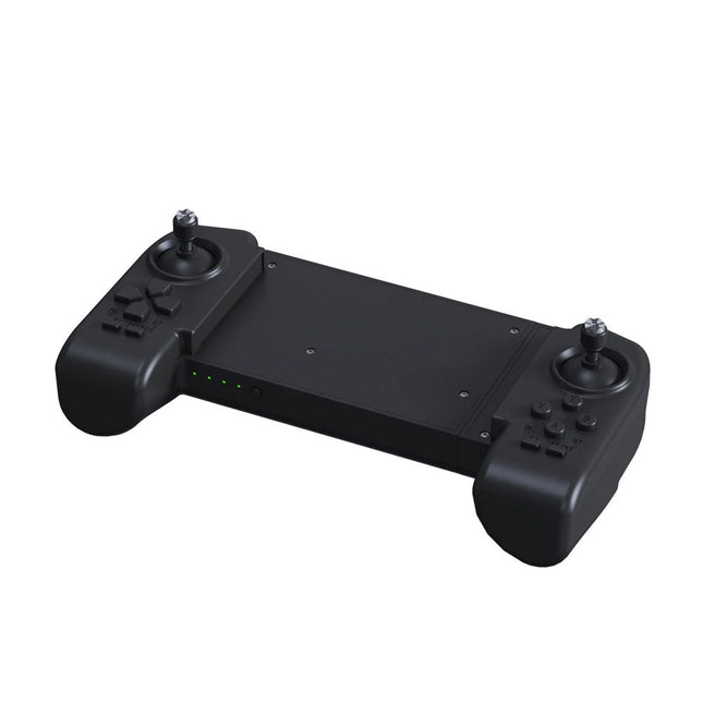
Unitree Unitree Go2 Remote Controller
The Unitree Go2 Controller is a dedicated remote control device designed for seamless and precise operation of the Unitree Go2 Quadruped Robot. This bimanual remote features built-in data transmission and Bluetooth modules, facilitating reliable wireless communication with the robot. It offers an ultra-long control distance of over 100 meters in open environments, ensuring flexibility in various operational scenarios. Specifications Charging Voltage 5 V Charging Current 2 A Frequency 2.4 GHz Communication Modes Data transmission module and Bluetooth Battery Capacity 2500 mAh Operating Time approx. 4.5 hours Control Distance Over 100 meters in open environments
€ 299,00
Best Price
-
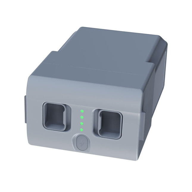
Unitree Unitree Go2 Spare Battery (15,000 mAh)
With a capacity of 15,000 mAh, the Unitree Go2 battery provides a robust power source that enables your robot to complete tasks with ease. Whether for complex exploration, research projects, or fun excursions, this powerful battery delivers the energy your robot needs. The runtime of the Unitree Go2 battery varies depending on the application and usage. Based on the functions and activities employed, the battery can offer between 2 to 4 hours of operation. This flexibility allows you to customize the robot as needed, enabling longer exploration missions or more extensive projects. The Unitree Go2 battery is a reliable companion for your robotics adventures. With its impressive capacity and adaptable runtime, it ensures your robot performs powerfully and with endurance, without frequent recharging. Whether you need the Unitree Go2 battery as a replacement or an upgrade for your robot, this powerful energy storage solution provides the perfect balance of performance and reliability. Specifications Rated voltage: DC 28.8 V Limited charging voltage: DC 33.6 V Charging current: 9 A Rated capacity: 15,000 mAh, 432 Wh Standard: IS 16046 (Part 2) / IEC 62133-2 Self-developed battery management system (BMS) Dimensions: 120 x 80 x 182 mm Functions: Power indicator Self-discharge protection of battery storage Equilibrium charge protection Overcharge protection Discharge protection Short circuit protection Battery charge detection protection
€ 795,00
Best Price
-
Elektor Digital Universal Display Book for PIC Microcontrollers (E-book)
The newcomer to Microchip’s PIC microcontrollers invariably gets an LED to flash as their first attempt to master this technology. You can use just a simple LED indicator in order to show that your initial attempt is working, which will give you confidence to move forward. This is how the book begins — simple programs to flash LEDs, and eventually by stages to use other display indicators such as the 7-segment display, alphanumeric liquid crystal displays and eventually a colour graphic LCD. As the reader progresses through the book, bigger and upgraded PIC chips are introduced, with full circuit diagrams and source code, both in assembler and C. In addition, a small tutorial is included using the MPLAB programming environment, together with the EAGLE schematic and PCB design package to enable readers to create their own designs using the book’s many case studies as working examples to work from.
€ 19,95
Members: € 17,96
-
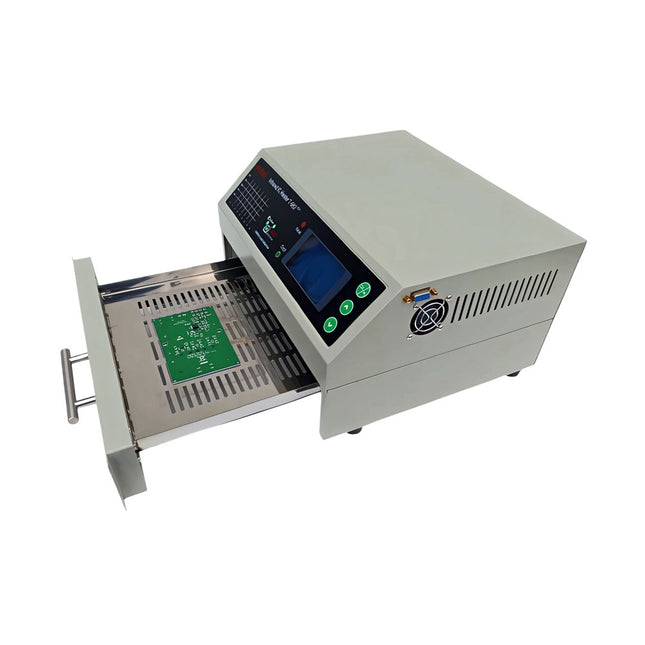
puhui Upgraded T-962 v2.0 Reflow Soldering Oven (Elektor Version)
This upgraded version 2.0 (available exclusively from Elektor) contains the following improvements: Enhanced protective earthing (PE) for furnace chassis Extra thermal insulation layer around furnace to reduce odors Connection to a computer, allowing curve editing on a PC Features such as constant temperature control and timing functions The infrared IC heater T-962 v2.0 is a microprocessor-controlled reflow oven that you can use for effectively soldering various SMD and BGA components. The whole soldering process can be completed automatically and it is very easy to use. This machine uses a powerful infrared emission and circulation of the hot air flow, so the temperature is being kept very accurate and evenly distributed. A windowed drawer is designed to hold the work-piece, and allows safe soldering techniques and the manipulation of SMDBGA and other small electronic parts mounted on a PCB assembly. The T-962 v2.0 may be used to automatically rework solder to correct bad solder joints, remove/replace bad components and complete small engineering models or prototypes. Features Large infrared soldering area Effective soldering area: 180 x 235 mm; this increases the usage range of this machine drastically and makes it an economical investment. Choice of different soldering cycles Parameters of eight soldering cycles are pre defined and the entire soldering process can completed automatically from Preheat, Soak and Reflow through to cool down. Special heat up and temperature equalization with all designs Uses up to 800 Watts of energy efficient Infrared heating and air circulation to re-flow solder. Ergonomic design, practical and easily operated Good build quality but at the same time light weight and a small footprint allows the T-962 v2.0 to be easily bench positioned transported or stored. Large number of available functions The T-962 v2.0 can solder most small parts of PCB boards, for example CHIP, SOP, PLCC, QFP, BGA etc. It is the ideal rework solution from single runs to on-demand small batch production. Specifications Soldering area (max) 180 x 235 mm (7.1 x 9.3") Power (max) 800 W Temperature range 0-280°C (32-536°F) Heating method Infrared Processing time 1~8 minutes Power supply 220 V AC/50 Hz Display LCD with Backlight Control mode 8 intelligent temperature curves Dimensions 310 x 290 x 170 mm (12.2 x 11.4 x 6.7") Weight 6.2 kg Included 1x T-962 v2.0 Reflow Soldering Oven (Elektor Version) 2x Fuses 1x Power cord (EU) Downloads Manual
€ 299,00€ 259,00
Best Price
-
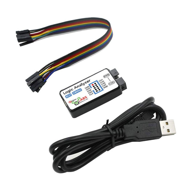
Elektor Labs USB Logic Analyzer (8-ch, 24 MHz)
This USB Logic Analyzer is an 8-channel logic analyzer with each input dual purposed for analog data recording. It is perfect for debugging and analyzing signals like I²C, UART, SPI, CAN and 1-Wire. It operates by sampling a digital input connected to a device under test (DUT) at a high sample rate. The connection to the PC is via USB. Specifications Channels 8 digital channels Maximum sampling rate 24 MHz Maximum input voltage 0~5 V Operating temperature 0~70°C Input impedance 1 MΩ || 10 pF Supported protocols I²C, SPI, UART, CAN, 1-Wire, etc. PC connection USB Dimensions 55 x 28 x 14 mm Included USB Logic Analyzer (8-ch, 24 MHz) USB Cable Jumper Wire Ribbon Cable Downloads Software
€ 14,95
Members: € 13,46
-

Elektor Digital Using Displays in Raspberry Pi Projects (E-book)
Learn to program displays and GUIs with Python This book is about Raspberry Pi 4 display projects. The book starts by explaining how to install the latest Raspbian operating system on an SD card, and how to configure and use the GPIO ports. The core of the book explains the following topics in simple terms with fully tested and working example projects: Simple LED projects Bar graph LED projects Matrix LED projects Bitmap LED projects LED strips LCDs OLED displays E-paper displays TFT displays 7-inch touch screen GUI Programming with Tkinder One unique feature of this book is that it covers almost all types of display that readers will need to use in their Raspberry Pi based projects. The operation of each project is fully given, including block diagrams, circuit diagrams, and commented full program listings. It is therefore an easy task to convert the given projects to run on other popular platforms, such as Arduino or PIC microcontrollers. Python program listings of all Raspberry Pi projects developed in this book are available for download at Elektor.com. Readers can use these programs in their projects. Alternatively, they can modify the programs to suit their applications.
€ 32,95
Members: € 29,66
-
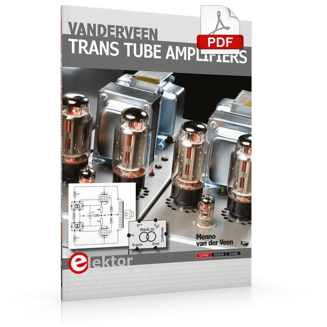
Elektor Digital Vanderveen Trans Tube Amplifiers (E-book)
Menno van der Veen is well known for his research publications on tube amplifiers used in audio systems. In this book he describes one of his research projects which focuses on the question of whether full compensation for distortion in tubes and output transformers is possible. In the past, a variety of techniques have been developed. One of them has largely been forgotten: trans-conductance, which means converting current into voltage or voltage into current. Menno van der Veen has breathed new life into this technique with his research project titled “Trans”. This book discusses all aspects of this method and discusses its pitfalls. These pitfalls are addressed one by one. The end result is a set of stringent requirements for Trans amplifiers. Armed with these requirements, Menno then develops new Trans amplifiers, starting with Transie 1 and Transie 2. These DC-coupled, single-ended tube amplifiers have unusually good characteristics and are suitable for hobbyist construction. Next the Trans principle is applied to amplifiers with higher output power. A trial-and-error process ultimately leads to the Vanderveen Trans 30 amplifier, which optimizes the features of Trans. The characteristics of this amplifier are so special and unique that Menno believes he has struck gold. To ensure that variations in tube characteristics cannot interfere with optimal Trans behavior, Menno makes use of simulations and comparison with other amplifier types. This book reads like an adventure story, but it is much more – it is an account of solid research into new ways to achieve optimal audio reproduction.
€ 29,95
Members: € 26,96
-

Elektor Publishing Vintage Radio Equipment
Resonances From Aether Days A Pictorial and Technical Analysis from WWII to the Internet Age From the birth of radio to the late 1980s, much of real life unfolded through shortwave communication. World War II demonstrated—beyond a shadow of a doubt—that effective communications equipment was a vital prerequisite for military success. In the postwar years, shortwave became the backbone on which many of the world's most critical services depended every day. All the radio equipment—through whose cathodes, grids, plates, and transistors so much of human history has flowed—is an exceptional subject of study and enjoyment for those of us who are passionate about vintage electronics. In this book, which begins in the aftermath of World War II, you’ll find a rich collection of information: descriptions, tips, technical notes, photos, and schematics that will be valuable for anyone interested in restoring—or simply learning about—these extraordinary witnesses to one of the most remarkable eras in technological history. My hope is that these pages will help preserve this vast treasure of knowledge, innovation, and history—a heritage that far transcends the purely technical.
€ 79,95
Members: € 71,96
-
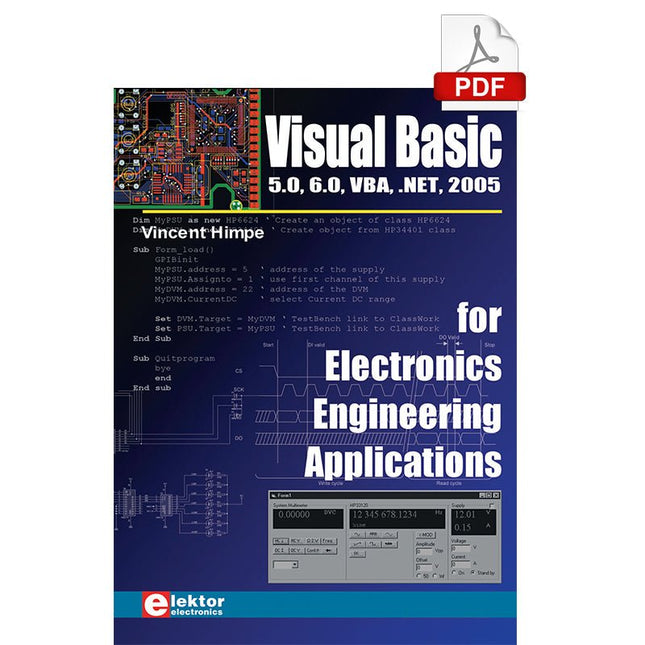
Elektor Digital Visual Basic for Electronics Engineering Applications (E-book)
The PC has long-time outgrown its function as a pure computer and has become an all-purpose machine. This book is targeted towards those people that want to control existing or self-built hardware from their computer. Using Visual Basic as Rapid Application Development tool we will take you on a journey to unlock the world beyond the connectors of the PC. After familiarising yourself with Visual Basic, its development environment and the toolset it offers, items such as serial communications, printer ports, bit-banging, protocol emulation, ISA, USB and Ethernet interfacing and the remote control of test-equipment over the GPIB bus, are covered in extent. Each topic is accompanied by clear, ready to run code, and where necessary, schematics are provided that will get your projects up to speed in no time. This book will show you advanced things like: using tools like Debug to find hardware addresses, setting up remote communication using TCP/IP and UDP sockets and even writing your own internet servers. Or how about connecting your own block of hardware over USB or Ethernet and controlling it from Visual Basic. Other things like internet-program communication, DDE and the new graphics interface of Windows XP are covered as well. All examples are ready to compile using Visual Basic 5.0, 6.0, NET or 2005. Extensive coverage is given on the differences between what could be called Visual Basic Classic and Visual basic .NET / 2005.
€ 39,95
Members: € 35,96
-

Weller Weller WE1010 Digital Soldering Station (70 W)
High-quality soldering station with the most important tools and consumables, ideal for universal soldering applications. Features 1-Channel Power Unit, digital, 70 W Power unit, 1 channel with soldering iron WEP 70 and safety rest PH 70 70W solder iron with ergonomic handle and providing toolless tip change ESD safe station, iron and heat-resistant silicon cable for safe handling Using ET soldering tips Standby mode and auto setback conserves energy, protects equipment Password-protected to preserve settings Specifications Dimensions: 150 x 120 x 98 mm Weight: 1.4 kg Display: Digital LC Display Temperature range: Adjustable from 100°C - 450°C (200°F - 850°F) Voltage: 230 V Channels: 1 Temperature range (depends on tool) °C: 100-450 Temperature range (depends on tool) °F: 200-850 Temperature accuracy °C: Average tip temperature can be „offset“ to +/- 5°C at idle with no load Temperature accuracy °F: Average tip temperature can be „offset“ to +/- 9°F at idle with no load Temperature stability °C: ±6 Temperature stability °F: ±10 Heat-up time (ca) in seconds (50-350°C / 120-660°F): 28 sec. Heating output: 85 W
€ 157,60
-

Weller Weller WT1010 Digital Soldering Station (90 W)
High-quality soldering with the most important tools and consumables, ideal for universal soldering applications. Features Power unit, 1 channel 1-channel Soldering Station digital 90 W (95 W) WTP 90: The soldering iron for universal use with power response tips. Tip family XNT & THM (high mass tips) Lock function Specifications Dimensions W x D x H (mm): 149 x 138 x 101 Dimensions W x D x H (inch): 5.87 x 5.43 x 3.98 Weight (ca) in kg: 1.9 Channels: 1 Voltage: 230 V, 50/60 Hz Heating output: 90 W (95 W) Temperature accuracy °C: ±9 Display: Backlit LCD Temperature range: Adjustable from 50°C - 450°C (150°F - 850°C)Adjustable temperature range varies among tools Temperature stability °C: ±2 Temperature accuracy °F: ±17 Temperature stability °F: ±4 Temperature range (depends on tool) °C: 100-450 Temperature range (depends on tool) °F: 150-850 Equipotential balance: yes Fuse: 0,5 A WT compatible: yes ESD-safe: yes Power cord: EMEA
€ 538,45
-

Weller Weller WT1013 Digital Soldering Station (95 W)
The Weller WT 1013 soldering station set includes the WT 1 supply unit, the WP 80 soldering iron and the WSR 201 safety rest. It is stackable and thus creates more space in the workplace. With an integrated usage sensor, the soldering tool switches off automatically. Specifications Channels 1 Voltage 230 V Power 95 W Display Backlit LCD Temperature range 50 °C - 450 °C Temperature stability ±2 °C Temperature accuracy ±9 °C Fuse 0.5 A Equipotential bonding on WT compatible on ESD-safe on Power cable EMEA Dimensions 149 x 138 x 101 mm Weight (approx.) 1.9 kg
€ 441,65
-

Velleman Whadda 3D Xmas Tree Kit
The Whadda 3D Xmas Tree Kit is aimed at hobbyists and beginners who are interested in soldering and electronics. With this DIY kit, you can build a festive LED Christmas tree. Features 16 flashing red LEDs Extra green and yellow LEDs provided to customise your tree Can be hung on and fed through wires Will operate on 12 V DC (e.g. in cars) Specifications Low power consumption 8 mA Power supply 9 V battery operation (not included) Dimensions 102 x 88 x 80 mm Weight 65 g Downloads Manual
€ 10,95
-

Velleman Whadda Electronic Dice
This electronic dice with 7 red LEDs rolls when the push button is released and works with a 9 V battery (not included). Downloads Manual
€ 6,50
-
Elektor Publishing Wireless Power Design
From Theory to Practical Applications in Wireless Energy Transfer and Harvesting Wireless power transmission has gained significant global interest, particularly with the rise of electric vehicles and the Internet of Things (IoT). It’s a technology that allows the transfer of electricity without physical connections, offering solutions for everything from powering small devices over short distances to long-range energy transmission for more complex systems. Wireless Power Design provides a balanced mix of theoretical knowledge and practical insights, helping you explore the potential of wireless energy transfer and harvesting technologies. The book presents a series of hands-on projects that cover various aspects of wireless power systems, each accompanied by detailed explanations and parameter listings. The following five projects guide you through key areas of wireless power: Project 1: Wireless Powering of Advanced IoT Devices Project 2: Wireless Powered Devices on the Frontline – The Future and Challenges Project 3: Wireless Powering of Devices Using Inductive Technology Project 4: Wireless Power Transmission for IoT Devices Project 5: Charging Robot Crawler Inside the Pipeline These projects explore different aspects of wireless power, from inductive charging to wireless energy transmission, offering practical solutions for real-world applications. The book includes projects that use simulation tools like CST Microwave Studio and Keysight ADS for design and analysis, with a focus on practical design considerations and real-world implementation techniques.
€ 39,95
Members: € 35,96
-

Elektor Digital Wireless Power Design (E-book)
From Theory to Practical Applications in Wireless Energy Transfer and Harvesting Wireless power transmission has gained significant global interest, particularly with the rise of electric vehicles and the Internet of Things (IoT). It’s a technology that allows the transfer of electricity without physical connections, offering solutions for everything from powering small devices over short distances to long-range energy transmission for more complex systems. Wireless Power Design provides a balanced mix of theoretical knowledge and practical insights, helping you explore the potential of wireless energy transfer and harvesting technologies. The book presents a series of hands-on projects that cover various aspects of wireless power systems, each accompanied by detailed explanations and parameter listings. The following five projects guide you through key areas of wireless power: Project 1: Wireless Powering of Advanced IoT Devices Project 2: Wireless Powered Devices on the Frontline – The Future and Challenges Project 3: Wireless Powering of Devices Using Inductive Technology Project 4: Wireless Power Transmission for IoT Devices Project 5: Charging Robot Crawler Inside the Pipeline These projects explore different aspects of wireless power, from inductive charging to wireless energy transmission, offering practical solutions for real-world applications. The book includes projects that use simulation tools like CST Microwave Studio and Keysight ADS for design and analysis, with a focus on practical design considerations and real-world implementation techniques.
€ 32,95
Members: € 29,66
-
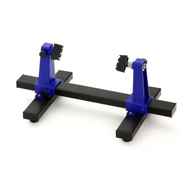
Zhongdi ZD-11E PCB Holder
This adjustable circuit board holder is ideal for clamping PCB for soldering, desoldering or rework. Features 2 adjustable grips on a retractable stand to accommodate various board sizes. The adjustable clamps allow the PCB to rotate 360 degrees and stay set in any position. The base of this rigid metal stand features four rubber feet to ensure stability. Specifications Product size 30 x 16.5 x 12.5 cm Max. holding size 20 x 14 cm Weight 450 g
€ 7,95
-

Zhongdi ZD-129A Magnifying LED Desk Lamp
This desk lamp is ideal for your workplace. With the 5-inch 5D-lens, the finest work can be done. The lamp has 80 integrated LEDs. Features Lens size: 5 inch Lens material: glass Diopter: 5D Light source: T5 22 W fluorescent energy-saving bulb (80pcs LED) Voltage: 220-240 V Power: 22 W
€ 50,00
-

Zhongdi ZD-153A Solder Fume Extractor
Fumes released during the soldering process are potentially harmful to health. This solder fume extractor is securely fastened to the work table with a bracket. Thanks to the 3 axes, the solder fume extractor can be positioned perfectly, i.e. directly above the rising solder fumes. The harmful solder fumes are extracted by a powerful but quiet fan and filtered by an activated-carbon filter mat. Features Removes solder fumes Absorbs toxic gases and fumes from brazing operations Helps reduce the likelihood of headaches, eye irration and neusea Adjustable absorption angle for accurate placement Easy replaceable activated carbon filter High-performance fan Low noise and long life service Specifications Absorption capacity: 1 m³/min (max.) Power consumption: 23 W Power supply: 220-240 VAC Amount of activated carbon filter: 7 g Maximum absorption weight: 2 g Dimensions: 220 x 270 x 168 mm (W x H x D) Weight: 1.4 kg
€ 52,95
-

Zhongdi ZD-8962B ESD Soldering Station (70 W)
The ZD-8962B soldering station features an adjustable temperature range of 160°C to 480°C with an output power of 70 W. Equipped with an integrated heating element in the soldering tip, the station reaches the desired operating temperature in just 8 seconds. A large digital display provides real-time monitoring, showing both the preset target and the actual temperature of the iron for precision control. Additionally, the station is ESD-safe, ensuring sensitive electronic components are fully protected from electrostatic discharge during use. Specifications Power 70 W Input voltage 220-240 V AC/50 Hz Output voltage 20 V Temperature range 160°C – 480°C (320°F – 896°F) Heating time ~8 s Display Large, two-line LED display for showing target and actual temperature Special features ESD protection, Sleep mode/energy-saving function, Switch between °C and °F Included ZD-8962B Soldering station unit Soldering iron Soldering tip N12-1 Soldering iron stand with copper brush and sponge Soldering wire stand with lead-free soldering wire (10 g) Power cable (EU) Manual
€ 69,95€ 59,95
Best Price
-
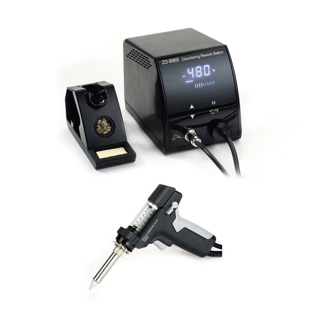
Zhongdi ZD-8965 Desoldering Station
The ZD-8965 is a digital temperature-controlled desoldering station equipped with ground protection and an LCD screen for temperature display. Despite its compact and robust design, this high-power desoldering station is easy to operate with just one hand. The ZD-8965 features a soldering gun with an integrated filter that captures any extracted material, allowing for continuous operation by simply replacing the filters. Additionally, a temperature sensor is embedded in the tip, enabling rapid response to temperature fluctuations for consistent performance. Features Effortlessly adjust the temperature between 160°C and 480°C using the convenient up/down buttons on the front panel. LED display to indicate the temperature in °C/°F Features an ergonomic pistol grip with a trigger for quick and efficient solder waste removal. The upgraded soldering gun includes a rear trigger, making it exceptionally convenient for replacing and cleaning components. Comes with a high-quality soldering gun and a sturdy holder. Equipped with a heavy-duty heater that ensures optimal desoldering performance every time. Specifications Station Voltage supply 220-240 V Power 140 W Vakuum pressure 600 mm HG Desoldering Gun Power 140 W (18 V DC)Heat up rating: 140 W Temperature 160-480°C (320-896°F) Heating element Ceramic heater Included 1x ZD-8965 Desoldering station 2x Spare soldering tips 3x Cleaning needles for desoldering tips 3x Spare filter for desoldering gun 1x Spare filter for desoldering station 1x Manual
€ 99,00


