With the availability of free and open source C/C++ compilers today, you might wonder why someone would be interested in assembler language. What is so compelling about the RISC-V Instruction Set Architecture (ISA)? How does RISC-V differ from existing architectures? And most importantly, how do we gain experience with the RISC-V without a major investment? Is there affordable hardware available?
The availability of the Espressif ESP32-C3 chip provides a way to get hands-on experience with RISC-V. The open sourced QEMU emulator adds a 64-bit experience in RISC-V under Linux. These are just two ways for the student and enthusiast alike to explore RISC-V in this book.
The projects in this book are boiled down to the barest essentials to keep the assembly language concepts clear and simple. In this manner you will have “aha!” moments rather than puzzling about something difficult. The focus in this book is about learning how to write RISC-V assembly language code without getting bogged down. As you work your way through this tutorial, you’ll build up small demonstration programs to be run and tested. Often the result is some simple printed messages to prove a concept. Once you’ve mastered these basic concepts, you will be well equipped to apply assembly language in larger projects.
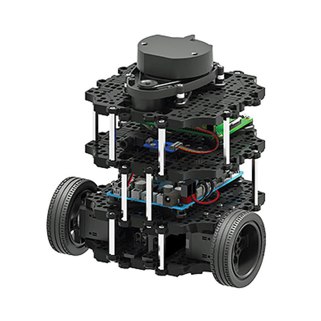
World’s Most Popular ROS Platform TurtleBot is the most popular open source robot for education and research. The new generation TurtleBot3 is a small, low cost, fully programmable, ROS based mobile robot. It is intended to be used for education, research, hobby and product prototyping. Affordable Cost TurtleBot was developed to meet the cost-conscious needs of schools, laboratories and companies. TurtleBot3 is the most affordable robot among the SLAM-able mobile robots equipped with a 360° Laser Distance Sensor LDS-01. Small Size The dimension of TurtleBot3 Burger is only 138 x 178 x 192 mm (L x W x H). Its size is about 1/4 of the size of the predecessor. Imagine keeping TurtleBot3 in your backpack and develop your program and test it anywhere you go. ROS Standard The TurtleBot brand is managed by Open Robotics, which develops and maintains ROS. Nowadays, ROS has become the go-to platform for all the roboticists around the world. TurtleBot can be integrated with existing ROS-based robot components, but TurtleBot3 can be an affordable platform for whom want to get started learning ROS. Extensibility TurtleBot3 encourages users to customize its mechanical structure with some alternative options: open source embedded board (as a control board), computer and sensors. TurtleBot3 Burger is a two-wheeled differential drive type platform but it is able to be structurally and mechanically customized in many ways: Cars, Bikes, Trailers and so on. Extend your ideas beyond imagination with various SBC, sensors and motors on a scalable structure. Modular Actuator for Mobile Robot TurtleBot3 is able to get a precise spatial data by using 2 DYNAMIXEL’s in the wheel joints. DYNAMIXEL XM series can be operated by one of 6 operating modes (XL series: 4 operating modes): Velocity control mode for wheels, Torque control mode or Position control mode for joint, etc. DYNAMIXEL can be used even to make a mobile manipulator which is light but can be precisely controlled with velocity, torque and position control. DYNAMIXEL is a core component that makes TurtleBot3 perfect. It is easy to assemble, maintain, replace and reconfigure. Open Control Board for ROS The control board is open-sourced in hardware wise and in software wise for ROS communication. The open source control board OpenCR1.0 is powerful enough to control not only DYNAMIXEL’s but also ROBOTIS sensors that are frequently being used for basic recognition tasks in cost effective way. Various sensors such as Touch sensor, Infrared sensor, Color sensor and a handful more are available. The OpenCR1.0 has an IMU sensor inside the board so that it can enhance precise control for countless applications. The board has 3.3 V, 5 V, 12 V power supplies to reinforce the available computer device lineups. Strong Sensor Lineups TurtleBot3 Burger uses enhanced 360° LiDAR, 9-Axis Inertial Measurement Unit and precise encoder for your research and development. Open Source The hardware, firmware and software of TurtleBot3 are open source which means that users are welcomed to download, modify and share source codes. All components of TurtleBot3 are manufactured with injection molded plastic to achieve low cost, however, the 3D CAD data is also available for 3D printing. Specifications Maximum translational velocity 0.22 m/s Maximum rotational velocity 2.84 rad/s (162.72 deg/s) Maximum payload 15 kg Size (L x W x H) 138 x 178 x 192 mm Weight (+ SBC + Battery + Sensors) 1 kg Threshold of climbing 10 mm or lower Expected operating time 2h 30m Expected charging time 2h 30m SBC (Single Board Computers) Raspberry Pi 4 (2 GB RAM) MCU 32-bit ARM Cortex-M7 with FPU (216 MHz, 462 DMIPS) Actuator XL430-W250 LDS (Laser Distance Sensor) 360 Laser Distance Sensor LDS-01 or LDS-02
IMU Gyroscope 3 AxisAccelerometer 3 Axis Power connectors 3.3 V/800 mA5 V/4 A12 V/1 A Expansion pins GPIO 18 pinsArduino 32 pin Peripheral 3x UART, 1x CAN, 1x SPI, 1x I²C, 5x ADC, 4x 5-pin OLLO DYNAMIXEL ports 3x RS485, 3x TTL Audio Several programmable beep sequences Programmable LEDs 4x User LED Status LEDs 1x Board status LED1x Arduino LED1x Power LED Buttons and Switches 2x Push buttons, 1x Reset button, 2x Dip switch Battery Lithium polymer 11.1 V 1800 mAh / 19.98 Wh 5C PC connection USB Firmware upgrade via USB / via JTAG Power adapter (SMPS) Input: 100-240 VAC 50/60 Hz, 1.5 A @maxOutput: 12 VDC, 5 A Downloads ROS Robot Programming GitHub E-Manual Community
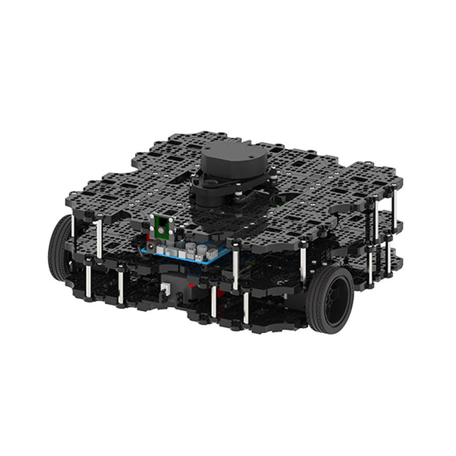
World’s Most Popular ROS Platform TurtleBot is the most popular open source robot for education and research. The new generation TurtleBot3 is a small, low cost, fully programmable, ROS based mobile robot. It is intended to be used for education, research, hobby and product prototyping. Affordable Cost TurtleBot was developed to meet the cost-conscious needs of schools, laboratories and companies. TurtleBot3 is the most affordable robot among the SLAM-able mobile robots equipped with a 360° Laser Distance Sensor LDS-01. ROS Standard The TurtleBot brand is managed by Open Robotics, which develops and maintains ROS. Nowadays, ROS has become the go-to platform for all the roboticists around the world. TurtleBot can be integrated with existing ROS-based robot components, but TurtleBot3 can be an affordable platform for whom want to get started learning ROS. Extensibility TurtleBot3 encourages users to customize its mechanical structure with some alternative options: open source embedded board (as a control board), computer and sensors. TurtleBot3 Waffle Pi is a two-wheeled differential drive type platform but it is able to be structurally and mechanically customized in many ways: Cars, Bikes, Trailers and so on. Extend your ideas beyond imagination with various SBC, sensors and motors on a scalable structure. Modular Actuator for Mobile Robot TurtleBot3 is able to get a precise spatial data by using 2 DYNAMIXEL’s in the wheel joints. DYNAMIXEL XM series can be operated by one of 6 operating modes (XL series: 4 operating modes): Velocity control mode for wheels, Torque control mode or Position control mode for joint, etc. DYNAMIXEL can be used even to make a mobile manipulator which is light but can be precisely controlled with velocity, torque and position control. DYNAMIXEL is a core component that makes TurtleBot3 perfect. It is easy to assemble, maintain, replace and reconfigure. Open Control Board for ROS The control board is open-sourced in hardware wise and in software wise for ROS communication. The open source control board OpenCR1.0 is powerful enough to control not only DYNAMIXEL’s but also ROBOTIS sensors that are frequently being used for basic recognition tasks in cost effective way. Various sensors such as Touch sensor, Infrared sensor, Color sensor and a handful more are available. The OpenCR1.0 has an IMU sensor inside the board so that it can enhance precise control for countless applications. The board has 3.3 V, 5 V, 12 V power supplies to reinforce the available computer device lineups. Open Source The hardware, firmware and software of TurtleBot3 are open source which means that users are welcomed to download, modify and share source codes. All components of TurtleBot3 are manufactured with injection molded plastic to achieve low cost, however, the 3D CAD data is also available for 3D printing. Specifications Maximum translational velocity 0.26 m/s Maximum rotational velocity 1.82 rad/s (104.27 deg/s) Maximum payload 30 kg Size (L x W x H) 281 x 306 x 141 mm Weight (+ SBC + Battery + Sensors) 1.8 kg Threshold of climbing 10 mm or lower Expected operating time 2h Expected charging time 2h 30m SBC (Single Board Computers) Raspberry Pi 4 (2 GB RAM) MCU 32-bit ARM Cortex-M7 with FPU (216 MHz, 462 DMIPS) Remote Controller RC-100B + BT-410 Set (Bluetooth 4, BLE) Actuator XL430-W210 LDS (Laser Distance Sensor) 360 Laser Distance Sensor LDS-01 or LDS-02
Camera Raspberry Pi Camera Module v2.1 IMU Gyroscope 3 AxisAccelerometer 3 Axis Power connectors 3.3 V/800 mA5 V/4 A12 V/1 A Expansion pins GPIO 18 pinsArduino 32 pin Peripheral 3x UART, 1x CAN, 1x SPI, 1x I²C, 5x ADC, 4x 5-pin OLLO DYNAMIXEL ports 3x RS485, 3x TTL Audio Several programmable beep sequences Programmable LEDs 4x User LED Status LEDs 1x Board status LED1x Arduino LED1x Power LED Buttons and Switches 2x Push buttons, 1x Reset button, 2x Dip switch Battery Lithium polymer 11.1 V 1800 mAh / 19.98 Wh 5C PC connection USB Firmware upgrade via USB / via JTAG Power adapter (SMPS) Input: 100-240 VAC 50/60 Hz, 1.5 A @maxOutput: 12 VDC, 5 A Downloads ROS Robot Programming GitHub E-Manual Community
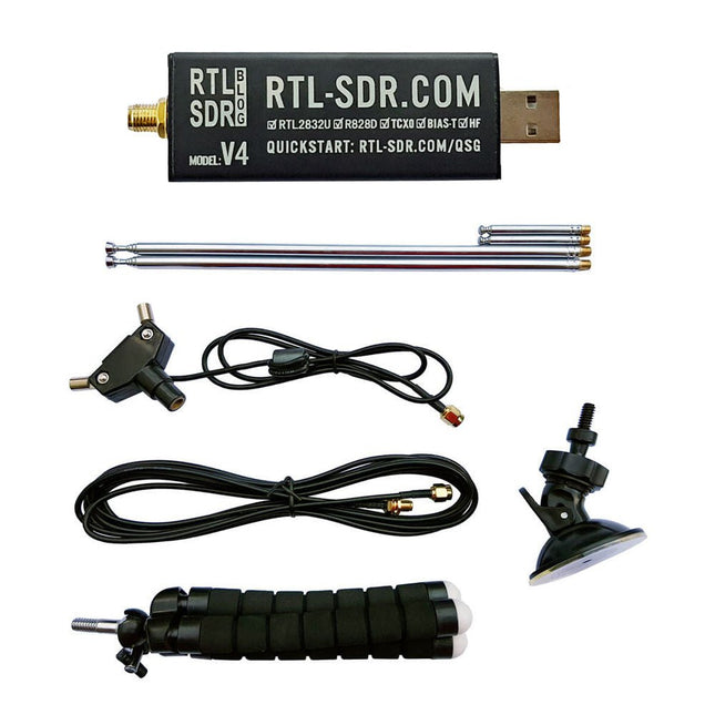
RTL-SDR is an affordable dongle that can be used as a computer-based radio scanner for receiving live radio signals between 500 kHz and 1.75 GHz in your area.
The RTL-SDR V4 offers several improvements over generic brands including use of the R828D tuner chip, triplexed input filter, notch filter, improved component tolerances, a 1 PPM temperature compensated oscillator (TCXO), SMA F connector, aluminium case with passive cooling, bias tee circuit, improved power supply, and a built in HF upconverter.
RTL-SDR V4 comes with the portable dipole antenna kit. It is great for beginners as it allows for terrestrial and satellite reception and easy to mount outdoors and designed for portable and temporary outside usage.
Features
Improved HF reception: V4 now uses a built-in upconverter instead of using a direct sampling circuit. This means no more Nyquist folding of signals around 14.4 MHz, improved sensitivity, and adjustable gain on HF. Like the V3, the lower tuning range remains at 500 kHz and very strong reception may still require front end attenuation/filtering.
Improved filtering: The V4 makes use of the R828D tuner chip, which has three inputs. The SMA input has been triplexed input into 3 bands: HF, VHF and UHF. This provides some isolation between the 3 bands, meaning out of band interference from strong broadcast stations is less likely to cause desensitization or imaging.
Improved filtering x2: In addition to the triplexing, the open drain pin on the R828D can be also used, which allows to add simple notch filters for common interference bands such as broadcast AM, broadcast FM and the DAB bands. These only attenuate by a few dB, but may still help.
Improved phase noise on strong signals: Due to an improved power supply design, phase noise from power supply noise has been significantly reduced.
Less heat: Another advantage of the improved power supply is low power consumption and less heat generation compared to the V3.
Included
1x RTL-SDR V4 dongle (R828D RTL2832U 1PPM TCXO SMA)
2x 23 cm to 1 m telescopic antenna
2x 5 cm to 13 cm telescopic antenna
1x Dipole antenna base with 60 cm RG174
1x 3 m RG174 extension cable
1x Flexible tripod mount
1x Suction cup mount
Downloads
Datasheet
User Guide
Quick Start Guide
SDR# User Guide
Dipole Antenna Guide
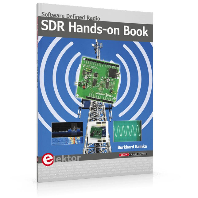
The short-wave technique has a very particular appeal: It can easily bridge long distances. By reflecting short-wave signals off the conductive layers of the ionosphere, they can be received in places beyond the horizon and therefore can reach anywhere on earth. Although technology is striving for ever higher frequencies, and radio is usually listened to on FM, DAB+, satellite or the Internet, modern means of transmission require extensive infrastructure and are extremely vulnerable. In the event of a global power outage, there is nothing more important than the short-wave. Amateur radio is not only a hobby, it’s also an emergency radio system!
Elektor’s SDR-Shield is a versatile shortwave receiver up to 30 MHz. Using an Arduino and the appropriate software, radio stations, morse signals, SSB stations, and digital signals can be received.
In this book, successful author and enthusiastic radio amateur, Burkhard Kainka describes the modern practice of software defined radio using the Elektor SDR Shield. He not only imparts a theoretical background but also explains numerous open source software tools.
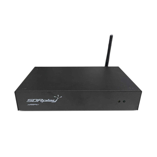
The nRSP-ST is a networked general coverage radio receiver for frequencies from 1 kHz to 2 GHz with up to 10 MHz of spectrum visibility. The nRSP-ST is your own personal remotely accessible SDR which can also be shared with a small number of trusted friends or colleagues.
The nRSP-ST addresses the needs of radio enthusiasts who want a 'plug-and-play' solution for remote reception. As well as achieving this, we have addressed typical internet bandwidth limitations with the creation of a novel IQ Lite mode, which efficiently delivers channels of IQ data. We are also introducing the ability to control and store IQ recordings at the remote location. The nRSP-ST is ideal for anyone wanting a wideband remote receiver without needing computer skills and hours of set-up time and ongoing maintenance at the remote location.
Features
"Plug and play" integrated, networked general coverage receiver:
Combines a receiver, a host computer and a whole lot more – all in one box!
Apply power and connect to the internet (Ethernet or Wi-Fi) and the nRSP-ST is automatically accessible from anywhere
Multi-platform SDRconnectTM software supports local operation or remote access on Windows, MacOS or Linux platforms
The nRSP-ST & SDRconnect are configurable for available network bandwidth:
In Full IQ mode, the nRSP-ST provides IQ data transfer of the visible spectrum bandwidth (e.g. for high-speed LAN or superfast internet connectivity)
In IQ Lite mode, the nRSP-ST provides IQ data of channels up to 192 kHz wide (e.g. for digital decoding by the client)
In Compact mode the nRSP-ST provides compressed audio (ideal for slower internet connections)
Supports multiple client connections with a simultaneous mixture of connection modes – an admin tool allows you to assign usernames and timeouts to trusted friends or colleagues.
All modes support visualization of up to 10 MHz spectrum bandwidth
Two remote connection options:
Use a remote SDRconnect client or
Use the built-in web-server for remote access from any web browsing capable device, including Android/iOS tablets and phones
The nRSP-ST offers the ability to record IQ and audio files to a NAS (network attached storage) device if available on the LAN.
The 14-bit ADC full featured wideband SDR receiver covers all frequencies from 1 kHz through VLF, LF, MW, HF, VHF, UHF and L-band to 2 GHz, with no gaps
Remotely monitor up to 10 MHz of spectrum at a time from a choice of 3 antennas
Flash upgradable for future feature enhancements
Included
1x nRSP-ST Receiver
1x WLAN antenna
1x Power supply
1x Manual
Downloads
Release notes
Software
The SDRplay RSP1B is an enhanced version of the popular RSP1A – a powerful, wideband, full-featured 14-bit SDR that covers the RF spectrum from 1 kHz to 2 GHz. The RSP1B comes in a rugged, black-painted steel case and offers significantly improved noise performance.
All it needs is a computer and an antenna to deliver excellent communications-receiver functionality. It includes a choice of SDRuno for Windows and the multi-platform SDRconnect software for Windows, macOS, and Linux (supplied free of charge by SDRplay). You can monitor up to 10 MHz of spectrum at a time.
A documented API allows developers to create new demodulators or applications for the platform.
Features
Covers all frequencies from 1 kHz through VLF, LF, MW, HF, VHF, UHF and L-band to 2 GHz, with no gaps
Receive, monitor and record up to 10 MHz of spectrum at a time
Free use of windows-based SDRuno software which provides an ever-increasing feature-set
Strong and growing software support network
Calibrated S meter/ RF power and SNR measurement with SDRuno (including datalogging to .CSV file capability)
Documented API provided to allow demodulator or application development on multiple platforms
Excellent dynamic range for challenging reception conditions
Works with popular 3rd party SDR software (including HDSDR, SDR Console and Cubic SDR)
ExtIO based plugin available
Software upgradeable for future standards
Strong and growing software support network
API provided to allow demodulator or application development
Multiplatform driver and API support including Windows, Linux, Mac, Android and Raspberry Pi
Up to 16 individual receivers in any 10 MHz slice of spectrum using SDRuno
Calibrated S meter and power measurements with SDRuno
Stand-alone windows-based spectrum analyser software available (with sweep, sample and hold features)
Ideal for monitoring of ISM/ IoT/ Telemetry bands <2 GHz
Ideal for portable operation
Specifications
Frequency Range
1 kHz – 2 GHz
Antenna Connector
SMA
Antenna Impedance
50 Ohms
Current Consumption (Typical)
185 mA (excl. Bias-T)
USB Connector
USB Type B
Maximum Input Power
+0 dBm Continuous+10 dBm Short Duration
ADC Sample Rates
2-10.66 MSPS
ADC Number of Bits
14 bit 2-6.048 MSPS12 bit 6.048-8.064 MSPS10 bit 8.064-9.216 MSPS8 bit >9.216 MSPS
Bias-T
4.7 V100 mA guaranteed
Reference
0.5ppm 24 MHz TCXO.Frequency error trimmable to 0.01ppm in field.
Operating Temperature Range
-10˚C to +60˚C
Dimensions
98 x 88 x 34 mm
Weight
110 g
Downloads
Datasheet
Software
RSP1B vs RSPdx vs RSPduo
RSP1B
RSPdx
RSPduo
Continuous coverage from 1 kHz to 2 GHz
✓
✓
✓
Up to 10 Mhz visible bandwidth
✓
✓
✓
14-bit ADC silicon technology plus multiple high-performance input filters
✓
✓
✓
Software selectable AM/FM & DAB broadcast band notch filters
✓
✓
✓
4.7 V Bias-T for powering external remote antenna amplifier
✓
✓
✓
Powers over the USB cable with a simple type B socket
✓
✓
✓
50Ω SMA antenna input(s) for 1 kHz to 2 GHz operation (software selectable)
1
2
2
Additional software selectable Hi-Z input for up to 30 Mhz operation
✓
Additional software selectable 50Ω BNC input for up to 200 MHz operation
✓
Additional LF/VLF filter for below 500 kHz
✓
24 MHz reference clock input (+ output on RSPduo)
✓
✓
Dual tuners enabling reception on 2 totally independent 2 MHz ranges
✓
Dual tuners enabling diversity reception using SDRuno
✓
Robust and strong plastic case (with internal RF shielding layer)
✓
Rugged black painted steel case
✓
✓
Overall performance below 2 MHz for MW and LF
+
++
+
Multiple simultaneous applications
+
+
++
Performance in challenging fading conditions (*using diversity tuning)
+
+
*++
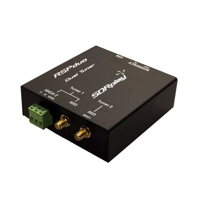
The SDRplay RSPduo is a high performance dual-tuner 14-bit SDR receiver. Housed in a high quality steel enclosure, each tuner can operate individually anywhere between 1 kHz and 2 GHz with up to 10 MHz of bandwidth or both tuners can operate simultaneously anywhere between 1 kHz and 2 GHz with up to 2 MHz of bandwidth per tuner.
A high stability reference along with external clocking features makes this device ideally suited to industrial, scientific & educational applications.
Features
Dual tuner provides independent coverage from 1 kHz to 2 GHz using 2 antenna ports simultaneously
14-bit ADC silicon technology
Up to 10 MHz visible bandwidth (single tuner mode) or 2 slices of 2 MHz spectrum (dual tuner mode)
3 software-selectable antenna ports (2x 50Ω and 1x 1kΩ high impedance balanced/unbalanced input)
High impedance antenna port (1 kHz to 30 MHz) with selectable MW notch filter and choice of 2 pre-selection filters
Software selectable AM/FM and DAB broadcast band notch filters for the 2 SMA antenna (1 kHz to 2 GHz) antenna ports
External clock input and output enables easy synchronisation to multiple RSPs or external reference clock
Powers over the USB cable with a simple type B socket
11 high-selectivity, built in front-end preselection filters on both the 2 SMA antenna ports
Software selectable multi-level Low Noise Preamplifier
Bias-T power supply for powering antenna-mounted LNA
Enclosed in a rugged black painted steel case.
SDRuno – World Class SDR software for Windows
Documented API for new apps development
Specifications
Frequency Range
1 kHz – 2 GHz
Antenna Connector
SMA
Antenna Impedance
50 Ohms
Current Consumption (Typical)
Single Tuner Mode: 180 mA (excl. Bias-T)Dual Tuner Mode: 280 mA (excl. Bias-T)
USB Connector
USB-B
Maximum Input Power
+0 dBm Continuous+10 dBm Short Duration
ADC Sample Rates
2-10.66 MSPS
ADC Number of Bits
14 bit 2-6.048 MSPS12 bit 6.048-8.064 MSPS10 bit 8.064-9.216 MSPS8 bit >9.216 MSPS
Bias-T
4.7 V100 mA guaranteed
Reference
High Temperature Stability (0.5ppm) 24 MHz TCXO.Frequency error trimmable to 0.01ppm in field.
Operating Temperature Range
−10˚C to +60˚C
Dimensions
98 x 94 x 33 mm
Weight
315 g
Downloads
Datasheet
Detailed Technical Information
Software
RSPdx-R2 vs RSPduo
RSPdx-R2
RSPduo
Continuous coverage from 1 kHz to 2 GHz
✓
✓
Up to 10 MHz visible bandwidth
✓
✓
14-bit ADC silicon technology plus multiple high-performance input filters
✓
✓
Software selectable AM/FM & DAB broadcast band notch filters
✓
✓
4.7 V Bias-T for powering external remote antenna amplifier
✓
✓
Powers over the USB cable with a simple type B socket
✓
✓
50Ω SMA antenna input(s) for 1 kHz to 2 GHz operation (software selectable)
2
2
Additional software selectable Hi-Z input for up to 30 Mhz operation
✓
Additional software selectable 50Ω BNC input for up to 200 MHz operation
✓
Additional LF/VLF filter for below 500 kHz
✓
24 MHz reference clock input (+ output on RSPduo)
✓
✓
Dual tuners enabling reception on 2 totally independent 2 MHz ranges
✓
Dual tuners enabling diversity reception using SDRuno
✓
Rugged black painted steel case
✓
✓
Overall performance below 2 MHz for MW and LF
++
+
Multiple simultaneous applications
+
++
Performance in challenging fading conditions (*using diversity tuning)
+
*++
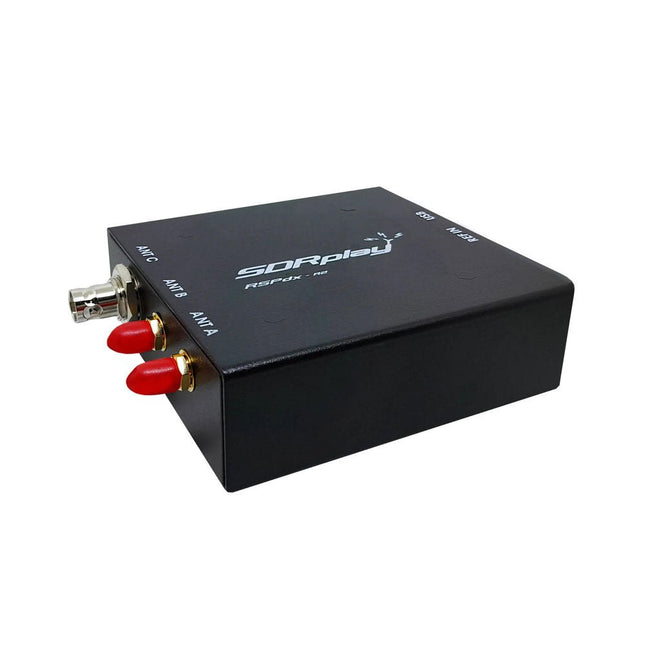
The SDRplay RSPdx-R2 is a wideband full featured single-tuner 14-bit SDR receiver which covers the entire RF spectrum from 1 kHz to 2 GHz giving up to 10 MHz of spectrum visibility. It contains three antenna ports, two of which use SMA connectors and operate across the full 1 kHz to 2 GHz range and the third uses a BNC connector which operates up to 200 MHz.
The RSPdx-R2 is an enhanced version of the RSPdx with further design improvements for use at frequencies below 2 MHz. Housed in a strong steel case, in addition to the functionality of the RSP1B, the RSPdx-R2 provides three software selectable antenna inputs and an external clock input. It offers excellent performance through HF and VHF frequencies all the way up to 2 GHz. The RSPdx-R2 also supports an "HDR mode" optimised for the demanding radio reception conditions below 2 MHz.
The RSPdx-R2, when used in conjunction with SDRplay’s own software, introduces a special HDR (High Dynamic Range) mode for reception within selected bands below 2 MHz. HDR mode delivers improved intermodulation performance and fewer spurious responses for those challenging bands.
Features
Covers all frequencies from 1 kHz through VLF, LF, MW, HF, VHF, UHF and L-band to 2 GHz, with no gaps
Receive, monitor and record up to 10 MHz of spectrum at a time
Significantly improved noise performance below 1 MHz (i.e. for some MF, LF and below)
Improved dynamic range below 2 MHz both in tuner mode and HDR mode
HDR mode below 2 MHz giving overall dynamic range and selectivity advantages
Software selectable choice of 3 antenna ports
External clock input for synchronisation purposes, or connection to GPS reference clock for extra frequency accuracy
Excellent dynamic range for challenging reception conditions
Free use of Windows-based SDRuno software (check website for versions supported)
Free use of SDRconnect SDR and server software for Windows, MacOS and Linux (Check website for versions supported)
Multiplatform driver and API support including Windows, Linux, Mac and Raspberry Pi 4/5
Strong and growing software support network
Calibrated S meter/RF power and SNR measurement with SDRuno (including datalogging to .CSV file capability)
Documented API provided to allow demodulator or application development on multiple platforms
Applications (Amateur)
Shortwave radio listening
Broadcast DXing (AM/FM/TV)
Panadaptor
Aircraft (ADS-B and ATC)
Slow Scan TV
Multi-amateur band monitoring
WSPR & digital modes
Weather fax (HF and satellite)
Satellite monitoring
Geostationary environmental satellites
Trunked radio
Utility and emergency service monitoring
Fast and effective antenna comparison
Applications (Industrial)
Spectrum Analyser
Surveillance
Wireless microphone monitoring
RF surveying
IoT receiver chain
Signal logging
RFI/EMC detection
Broadcast integrity monitoring
Spectrum monitoring
Power measurement
Applications (Educational/Scientific)
Teaching
Receiver design
Radio astronomy
Passive radar
Ionosonde
Spectrum analyser
Receiver for IoT sensor projects
Antenna research
Specifications
Frequency Range
1 kHz – 2 GHz
Antenna Connector
SMA
Antenna Impedance
50 Ohms
Current Consumption (Typical)
190 mA @ >60 MHz (excl. Bias-T)120 mA @ <60 MHz (excl. Bias-T)
USB Connector
USB-B
Maximum Input Power
+0 dBm Continuous+10 dBm Short Duration
ADC Sample Rates
2-10.66 MSPS
ADC Number of Bits
14 bit 2-6.048 MSPS12 bit 6.048-8.064 MSPS10 bit 8.064-9.216 MSPS8 bit >9.216 MSPS
Bias-T
4.7 V100 mA guaranteed
Reference
0.5ppm 24 MHz TCXOFrequency error trimmable to 0.01ppm in field
Operating Temperature
−10˚C to +60˚C
Dimensions
113 x 94 x 35 mm
Weight
315 g
Downloads
Datasheet
Software
RSPdx-R2 vs RSPduo
RSPdx-R2
RSPduo
Continuous coverage from 1 kHz to 2 GHz
✓
✓
Up to 10 MHz visible bandwidth
✓
✓
14-bit ADC silicon technology plus multiple high-performance input filters
✓
✓
Software selectable AM/FM & DAB broadcast band notch filters
✓
✓
4.7 V Bias-T for powering external remote antenna amplifier
✓
✓
Powers over the USB cable with a simple type B socket
✓
✓
50Ω SMA antenna input(s) for 1 kHz to 2 GHz operation (software selectable)
2
2
Additional software selectable Hi-Z input for up to 30 Mhz operation
✓
Additional software selectable 50Ω BNC input for up to 200 MHz operation
✓
Additional LF/VLF filter for below 500 kHz
✓
24 MHz reference clock input (+ output on RSPduo)
✓
✓
Dual tuners enabling reception on 2 totally independent 2 MHz ranges
✓
Dual tuners enabling diversity reception using SDRuno
✓
Rugged black painted steel case
✓
✓
Overall performance below 2 MHz for MW and LF
++
+
Multiple simultaneous applications
+
++
Performance in challenging fading conditions (*using diversity tuning)
+
*++
The starter kit for Jetson Nano is one of the best kits for beginners to get started with Jetson Nano. This kit includes 32 GB MicroSD card, 20 W adapter, 2-pin jumper, camera, and micro-USB cable.
Features
32 GB High-performance MicroSD card
5 V 4 A power supply with 2.1 mm DC barrel connector
2-pin jumper
Raspberry Pi camera module V2
Micro-B To Type-A USB cable with DATA enabled
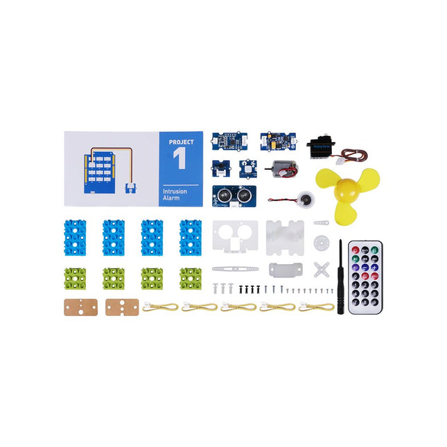
This is an add-on kit for the Seeed Studio Grove Beginner Kit for Arduino.
Applications
Suitable for Arduino beginners
Suitable for infrared control and motion detect
Suitable for getting started with open-source hardware and Arduino coding
Included
1x Grove Water Atomization
1x Grove Mini Fan
1x Grove Servo
1x Grove Ultrasonic Distance Sensor
1x Grove Infrared Receiver
1x Grove Mini PIR Motion Sensor
1x Grove Green Wrapper
1x Grove Blue Wrapper
5x Grove Cable
1x Infrared Remote Control Key
1x Ultrasonic Sensor Bracket Set
1x Motor Bracket Set
1x Servo Base
Features Integrated Cold-Junction Compensation Supported Types (designated by NIST ITS-90): Type K, J, T, N, S, E, B and R Four Programmable Temperature Alert Outputs: Monitor Hot- or Cold-Junction Temperatures Detect rising or falling temperatures Up to 255°C of Programmable Hysteresis Programmable Digital Filter for Temperature Low Power Dimensions: 20 mm x 40 mm x 18 mm Weight: 18 g Application Petrochemical Thermal Management Hand-Held Measurement Equipment Industrial Equipment Thermal Management Ovens Industrial Engine Thermal Monitor Temperature Detection Racks Downloads Eagle Files Github library Datasheet
The GrovePi+ is an easy-to-use and modular system for hardware hacking with the Raspberry Pi, no need for soldering or breadboards: plug in your Grove sensors and start programming directly.
Grove is an easy-to-use collection of more than 100 inexpensive plug-and-play modules that sense and control the physical world. By connecting Grove Sensors to Raspberry Pi, it empowers your Pi in the physical world. With hundreds of sensors to choose from Grove families, the possibilities for interaction are endless.
Set-up in 4 simple steps
Slip the GrovePi+ board over your Raspberry Pi
Connect the Grove modules to the GrovePi+ board
Upload your program to Raspberry Pi
Begin taking in the world data
The minimalist design and the spring loaded test needle makes it possible to simultaneously measure on fine pitch components and nearby signals.
The probe is steady but yet flexible made for instant measurements or total hands-free operations together with your multimeter, logic analyzer or preferred tool.
The dual pin header connector fits directly on a 2.54 mm (0.100”) connector.
The SP10 comes with a powerful magnet in the base, as for all PCBite probes and holders which makes the probe easy to place and reposition.
Included
4x PCBite holder
1x Large base plate (A4)
4x PCBite probe with pin tipped test needle
4x Extra crown tipped test needle
1x Set of yellow insulation washers
5x Dupont to dupont test wire
2x Banana to dupont test wire
1x Microfiber cloth
Downloads
User Guide
PCBite is the complete solution handling your circuit board during the development phase. Powerful magnets together with a stainless base plate makes the system flexible, mobile and user friendly.
The holder can easily be repositioned to handle circuit boards of varying shape and sizes.
The probes are steady but yet flexible made for instant measurements or total hands-free operations together with your multimeter or prefered tool.
Included
4x PCBite holder
2x Banana to DuPont test wires red/black
2x SP10 probe with red/black probe head and pin tipped test needles
2x Extra crown tipped test needle
1x Set of yellow insulation washers
1x Large Baseplate (A4)
1x Microfiber cloth
Downloads
User Guide
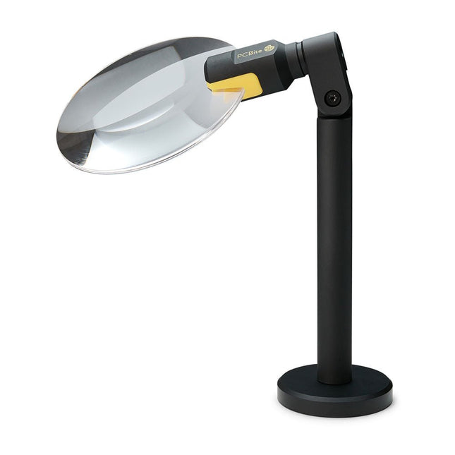
The PCBite Magnifier (premium build quality made from CNC machined aluminum) enlarges your target and makes it easier to see during soldering, inspection and measurements. Especially useful when placing PCBite hands free probes on fine pitch SMD components during measurements.
3x magnification edgeless lens for increased visibility of the work surface and AR coating (anti-reflection) to reduce reflections from nearby light sources.
Optimized design, magnification and focal point for use together with the PCBite PCB holders and baseplates included in all PCBite kits. Can also be used handheld but not standalone without a metal surface as base.
At the bottom of the magnifier foot there is a strong magnet perfectly balanced in strength. A low friction bottom cap protects the magnet and the baseplate to make the magnifier easy to slide when repositioning or removing the magnifier from the baseplate.
Friction based adjustment of lens tilt and rotate positions takes away the need for annoying and complicated set screws.
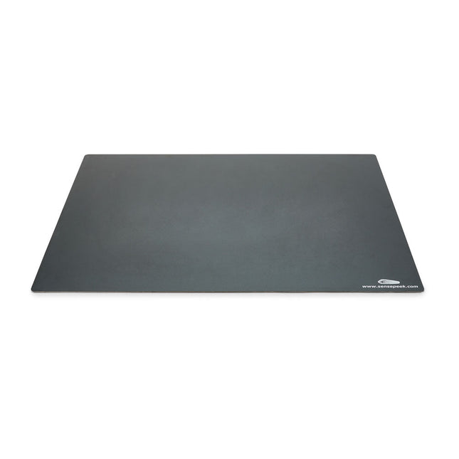
Components are both shrinking and getting increasingly finer pitch year after year but your PCBs might have grown in size or the number of interconnected PCBs or the number of handsfree PCBite probes needed to test your design may have increased making it crowded on our other smaller base plates.
Features
With a size of 297 x 420 mm (DIN A3) the extra large baseplate has room for most PCBs and many handsfree PCBite probes for those measurements sessions where more channels than available is needed.
So if you are looking for more space, extra protection or just want to clean up your work surface then this accessory is a perfect match.
Designed to be used with Sensepeeks magnetic PCBite line of products including PCB holders, hands free probes and magnifier.
Included
1x XL base plate (DIN A3) with pre-fitted insulation cover
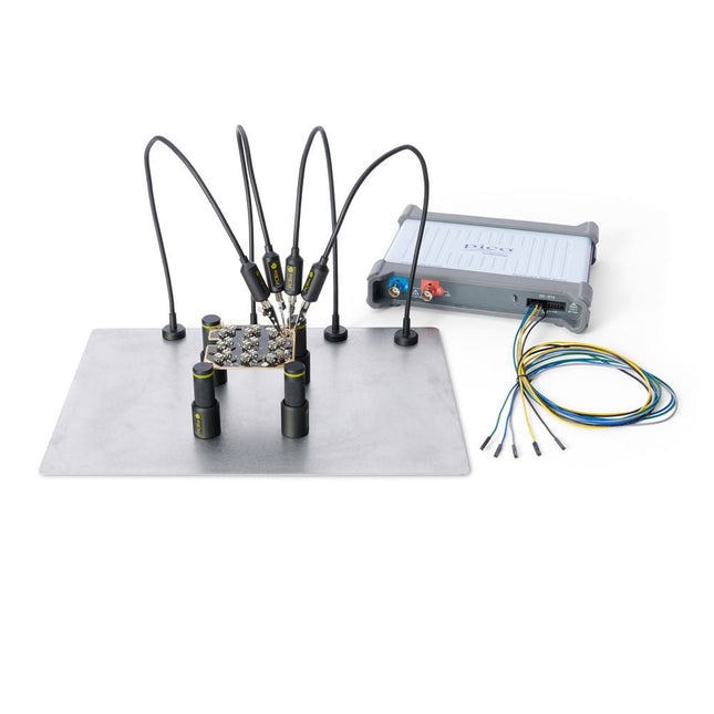
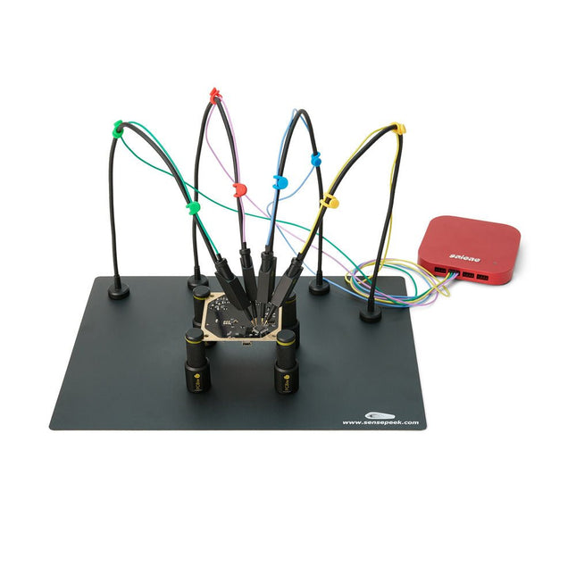
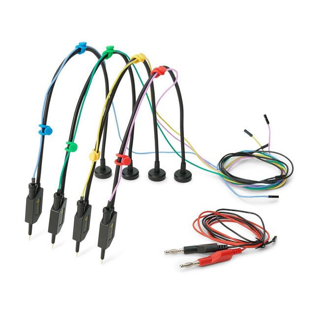
The SQ series of handsfree PCBite probes from Sensepeek are insulated, come with included color-coded cable holders and have a lower point of gravity making them even more stable compared with the original SP series of probes. All the loved features of handsfree measurement, exchangeable fine pitch spring tipped test needle and the minimalistic design is maintained to make traditional sized and handheld probes obsolete.
Features
All handsfree probes from Sensepeek makes instant measurements or long triggering sessions a breeze.
No more soldering wires to connect your probe or complicated tools to setup, just positioning the probe needle on any test point or component in the signal path and release.
Saves time and frustration during development, verification and repairs.
The minimalist design and the spring-loaded test needle makes it possible to simultaneously measure on fine pitch components and nearby signals.
Both length and weight of the SQ probes are perfectly balanced to be used with the included PCB holders and base plate which is a must for handsfree function.
The probe holder comes with a powerful magnet in the base, as for all PCBite probes and holders which makes the probe easy to place and reposition.
The SQ series of probes can be used handheld without the probe holder as they have an insulated grip but their full potential is used when measuring handsfree.
One side of the included baseplate is matte and the other is mirror polished. The mirror polished surface makes it easy to see components on the circuit board underside. For added protection during measurement the included insulation cover can be mounted on one of the surfaces.
Included
4x PCBite PCB holders
1x Set of yellow insulation washers for the PCB holders
1x Large Base plate (A4)
1x Insulation cover for the base plate (A4)
1x Micro fiber cloth
4x SQ10 probes and pin tipped test needles (black)
2x Banana to dupont test wires (red/black)
5x Dupont to dupont test wires
1x Set of cable holders (4 colors)
4x Extra test needles
Downloads
User guide (PCBite kit)
User guide (SQ10 probes)
The SQ series of handsfree PCBite probes from Sensepeek are insulated, come with included color-coded cable holders and have a lower point of gravity making them even more stable compared with the original SP series of probes. All the loved features of handsfree measurement, exchangeable fine pitch spring tipped test needle and the minimalistic design is maintained to make traditional sized and handheld probes obsolete.
Features
All handsfree probes from Sensepeek makes instant measurements or long triggering sessions a breeze.
No more soldering wires to connect your probe or complicated tools to setup, just positioning the probe needle on any test point or component in the signal path and release.
Saves time and frustration during development, verification and repairs.
The minimalist design and the spring-loaded test needle makes it possible to simultaneously measure on fine pitch components and nearby signals.
Both length and weight of the SQ probes are perfectly balanced to be used with PCBite PCB holders and base plate which is a must for handsfree function.
The probe holder comes with a powerful magnet in the base, as for all PCBite probes and holders which makes the probe easy to place and reposition.
The SQ series of probes can be used handheld without the probe holder as they have an insulated grip but their full potential is used when measuring handsfree.
Included
4x SQ10 probes and pin tipped test needles (black)
2x Banana to dupont test wires (red/black)
5x Dupont to dupont test wires
1x Set of cable holders (4 colors)
4x Extra test needles
Downloads
User guide
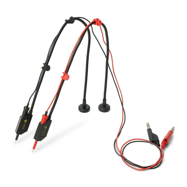
The SQ series of handsfree PCBite probes from Sensepeek are insulated, come with included color-coded cable holders and have a lower point of gravity making them even more stable compared with the original SP series of probes. All the loved features of handsfree measurement, exchangeable fine pitch spring tipped test needle and the minimalistic design is maintained to make traditional sized and handheld probes obsolete.
Features
All handsfree probes from Sensepeek makes instant measurements or long triggering sessions a breeze.
No more soldering wires to connect your probe or complicated tools to setup, just positioning the probe needle on any test point or component in the signal path and release.
Saves time and frustration during development, verification and repairs. The minimalist design and the spring-loaded test needle makes it possible to simultaneously measure on fine pitch components and nearby signals.
Both length and weight of the SQ probes are perfectly balanced to be used with PCBite PCB holders and base plate which is a must for handsfree function.
The probe holder comes with a powerful magnet in the base, as for all PCBite probes and holders which makes the probe easy to place and reposition.
The SQ series of probes can be used handheld without the probe holder as they have an insulated grip but their full potential is used when measuring handsfree.
Included
2x SQ10 probes and pin tipped test needles (red/black)
2x Banana to dupont test wires (red/black)
1x Set of cable holders (red/black)
2x Extra test needles
Downloads
User guide
The SQ series of handsfree PCBite probes from Sensepeek are insulated, come with included color-coded cable holders and have a lower point of gravity making them even more stable compared with the original SP series of probes. All the loved features of handsfree measurement, exchangeable fine pitch spring tipped test needle and the minimalistic design is maintained to make traditional sized and handheld probes obsolete.
Features
All handsfree probes from Sensepeek makes instant measurements or long triggering sessions a breeze.
No more soldering wires to connect your probe or complicated tools to setup, just positioning the probe needle on any test point or component in the signal path and release.
Saves time and frustration during development, verification and repairs.
The minimalist design and the spring-loaded test needle makes it possible to simultaneously measure on fine pitch components and nearby signals.
Both length and weight of the SQ probes are perfectly balanced to be used with PCBite PCB holders and base plate which is a must for handsfree function.
The probe holder comes with a powerful magnet in the base, as for all PCBite probes and holders which makes the probe easy to place and reposition.
The SQ series of probes can be used handheld without the probe holder as they have an insulated grip but their full potential is used when measuring handsfree.
Included
4x PCBite PCB holders
2x SQ10 probes and pin tipped test needles (red/black)
2x Banana to dupont test wires (red/black)
1x Large Base plate (A4)
1x Insulation cover for the base plate (A4)
1x Set of yellow insulation washers for the PCB holders
1x Set of cable holders (red/black)
2x Extra test needles
1x Micro fiber cloth
Downloads
User Guide (PCBite Kit)
User Guide (SQ10)
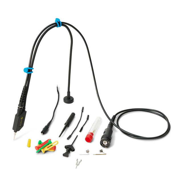
The SQ series of handsfree probes from Sensepeek have a lower point of gravity making them even more stable compared with the original SP series of handsfree probes. All probes in the SQ series are also insulated and can be used handheld as any traditional probe but their full potential is used when measuring handsfree.
Features
The SQ series of handsfree probes from Sensepeek have a lower point of gravity making them even more stable compared with the original SP series of handsfree probes.
All probes in the SQ series are also insulated and can be used handheld as any traditional probe but their full potential is used when measuring handsfree.
The SQ series of oscilloscope probes also includes more ground options, have probe tip protection, longer cable and support for oscilloscopes with automatic scaling (10:1).
All the loved features of handsfree measurement, exchangeable fine pitch spring tipped test needle, color-coded cable holders and the minimalistic design is maintained to make traditional sized and handheld probes obsolete.
Both length and weight of the SQ probes are perfectly balanced to be used with PCBite PCB holders and base plate which is a must for handsfree function.
Included
1x SQ200 200 MHz probe with spring tipped test needle
1x SQ probe holder for handsfree measurement
1x Testhook with detachable cables (5 cm & 10 cm) for convenient ground connection
1x Alligator cable for convenient ground connection
1x Standard ground spring, for handheld measurements at rated bandwidth
1x Unique ground spring, for total handsfree measurements at rated bandwidth
1x Set of color coded cable holders (4 colors)
1x Probe tip protection
1x Extra test needle
Downloads
User Guide SQXX0 Rev1.2
The SQ series of handsfree probes from Sensepeek have a lower point of gravity making them even more stable compared with the original SP series of handsfree probes. All probes in the SQ series are also insulated and can be used handheld as any traditional probe but their full potential is used when measuring handsfree.
The SQ series of oscilloscope probes also includes more ground options, have probe tip protection, longer cable and support for oscilloscopes with automatic scaling (10:1).
All the loved features of handsfree measurement, exchangeable fine pitch spring tipped test needle, color-coded cable holders and the minimalistic design is maintained to make traditional sized and handheld probes obsolete.
Both length and weight of the SQ probes are perfectly balanced to be used with PCBite PCB holders and base plate which is a must for handsfree function.
Features
Passive 10:1 probe with support for oscilloscopes with automatic scaling
Spring-loaded test needle for fine pitch measurements
Multiple ground options
Color coded cable holders
Probe tip protection
Insulated, can be used handheld
Improved probe holder for handsfree measurement when used with PCBite PCB holders
Included
1x SQ350 350 MHz probe with spring tipped test needle
1x SQ probe holder for handsfree measurement
1x Testhook with detachable cables (5 cm & 10 cm) for convenient ground connection
1x Alligator cable for convenient ground connection
1x Standard ground spring, for handheld measurements at rated bandwidth
1x Unique ground spring, for total handsfree measurements at rated bandwidth
1x Set of color coded cable holders (4 colors)
1x Probe tip protection
1x Extra test needle
Downloads
User Guide SQXX0 Rev1.1