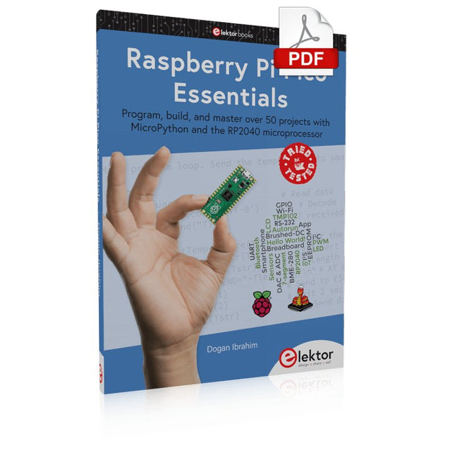
Program, build, and master over 50 projects with MicroPython and the RP2040 microprocessor The Raspberry Pi Pico is a high-performance microcontroller module designed especially for physical computing. Microcontrollers differ from single-board computers, like the Raspberry Pi 4, in not having an operating system. The Raspberry Pi Pico can be programmed to run a single task very efficiently within real-time control and monitoring applications requiring speed. The ‘Pico’ as we call it, is based on the fast, efficient, and low-cost dual-core ARM Cortex-M0+ RP2040 microcontroller chip running at up to 133 MHz and sporting 264 KB of SRAM, and 2 MB of Flash memory. Besides its large memory, the Pico has even more attractive features including a vast number of GPIO pins, and popular interface modules like ADC, SPI, I²C, UART, and PWM. To cap it all, the chip offers fast and accurate timing modules, a hardware debug interface, and an internal temperature sensor. The Raspberry Pi Pico is easily programmed using popular high-level languages such as MicroPython and or C/C++. This book is an introduction to using the Raspberry Pi Pico microcontroller in conjunction with the MicroPython programming language. The Thonny development environment (IDE) is used in all the projects described. There are over 50 working and tested projects in the book, covering the following topics: Installing the MicroPython on Raspberry Pi Pico using a Raspberry Pi or a PC Timer interrupts and external interrupts Analogue-to-digital converter (ADC) projects Using the internal temperature sensor and external temperature sensor chips Datalogging projects PWM, UART, I²C, and SPI projects Using Wi-Fi and apps to communicate with smartphones Using Bluetooth and apps to communicate with smartphones Digital-to-analogue converter (DAC) projects All projects given in the book have been fully tested and are working. Only basic programming and electronics experience is required to follow the projects. Brief descriptions, block diagrams, detailed circuit diagrams, and full MicroPython program listings are given for all projects described. Readers can find the program listings on the Elektor web page created to support the book.
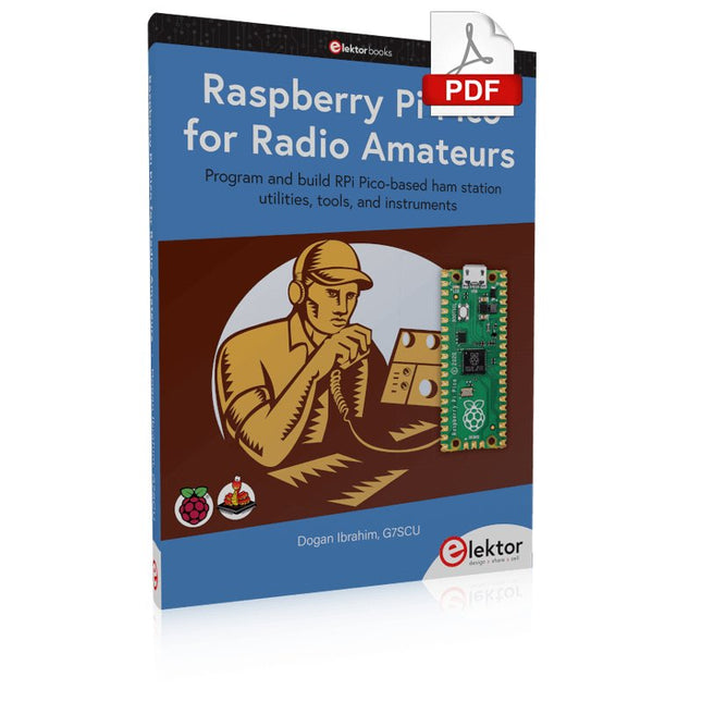
Program and build RPi Pico-based ham station utilities, tools, and instruments
Although much classical HF and mobile equipment is still in use by large numbers of amateurs, the use of computers and digital techniques has now become very popular among amateur radio operators. Nowadays, anyone can purchase a €5 Raspberry Pi Pico microcontroller board and develop many amateur radio projects using the “Pico” and some external components. This book is aimed at amateur radio enthusiasts, Electronic Engineering students, and anyone interested in learning to use the Raspberry Pi Pico to shape their electronic projects. The book is suitable for beginners in electronics as well as for those with wide experience.
Step-by-step installation of the MicroPython programming environment is described. Some knowledge of the Python programming language is helpful to be able to comprehend and modify the projects given in the book. The book introduces the Raspberry Pi Pico and gives examples of many general-purpose, software-only projects that familiarize the reader with the Python programming language. In addition to the software-only projects tailored to the amateur radio operator, Chapter 6 in particular presents over 36 hardware-based projects for “hams”, including:
Station mains power on/off control
Radio station clock
GPS based station geographical coordinates
Radio station temperature and humidity
Various waveform generation methods using software and hardware (DDS)
Frequency counter
Voltmeter / ammeter / ohmmeter / capacitance meter
RF meter and RF attenuators
Morse code exercisers
RadioStation Click board
Raspberry Pi Pico based FM radio
Using Bluetooth and Wi-Fi with Raspberry Pi Pico
Radio station security with RFID
Audio amplifier module with rotary encoder volume control
Morse decoder
Using the FS1000A TX-RX modules to communicate with Arduino
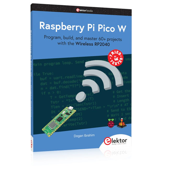
Program, build, and master 60+ projects with the Wireless RP2040
The Raspberry Pi Pico and Pico W are based on the fast, efficient, and low-cost dual-core ARM Cortex M0+ RP2040 microcontroller chip running at up to 133 MHz and sporting 264 KB of SRAM and 2 MB of Flash memory. Besides spacious memory, the Pico and Pico W offer many GPIO pins, and popular peripheral interface modules like ADC, SPI, I²C, UART, PWM, timing modules, a hardware debug interface, and an internal temperature sensor.
The Raspberry Pi Pico W additionally includes an on-board Infineon CYW43439 Bluetooth and Wi-Fi chipset. At the time of writing this book, the Bluetooth firmware was not yet available. Wi-Fi is however fully supported at 2.4 GHz using the 802.11b/g/n protocols.
This book is an introduction to using the Raspberry Pi Pico W in conjunction with the MicroPython programming language. The Thonny development environment (IDE) is used in all of the 60+ working and tested projects covering the following topics:
Installing the MicroPython on Raspberry Pi Pico using a Raspberry Pi or a PC
Timer interrupts and external interrupts
Analogue-to-digital converter (ADC) projects
Using the internal temperature sensor and external sensor chips
Using the internal temperature sensor and external temperature sensor chips
Datalogging projects
PWM, UART, I²C, and SPI projects
Using Bluetooth, WiFi, and apps to communicate with smartphones
Digital-to-analogue converter (DAC) projects
All projects are tried & tested. They can be implemented on both the Raspberry Pi Pico and Raspberry Pi Pico W, although the Wi-Fi-based subjects will run on the Pico W only. Basic programming and electronics experience are required to follow the projects. Brief descriptions, block diagrams, detailed circuit diagrams, and full MicroPython program listings are given for all projects.
Program, build, and master 60+ projects with the Wireless RP2040
The Raspberry Pi Pico and Pico W are based on the fast, efficient, and low-cost dual-core ARM Cortex M0+ RP2040 microcontroller chip running at up to 133 MHz and sporting 264 KB of SRAM and 2 MB of Flash memory. Besides spacious memory, the Pico and Pico W offer many GPIO pins, and popular peripheral interface modules like ADC, SPI, I²C, UART, PWM, timing modules, a hardware debug interface, and an internal temperature sensor.
The Raspberry Pi Pico W additionally includes an on-board Infineon CYW43439 Bluetooth and Wi-Fi chipset. At the time of writing this book, the Bluetooth firmware was not yet available. Wi-Fi is however fully supported at 2.4 GHz using the 802.11b/g/n protocols.
This book is an introduction to using the Raspberry Pi Pico W in conjunction with the MicroPython programming language. The Thonny development environment (IDE) is used in all of the 60+ working and tested projects covering the following topics:
Installing the MicroPython on Raspberry Pi Pico using a Raspberry Pi or a PC
Timer interrupts and external interrupts
Analogue-to-digital converter (ADC) projects
Using the internal temperature sensor and external sensor chips
Using the internal temperature sensor and external temperature sensor chips
Datalogging projects
PWM, UART, I²C, and SPI projects
Using Bluetooth, WiFi, and apps to communicate with smartphones
Digital-to-analogue converter (DAC) projects
All projects are tried & tested. They can be implemented on both the Raspberry Pi Pico and Raspberry Pi Pico W, although the Wi-Fi-based subjects will run on the Pico W only. Basic programming and electronics experience are required to follow the projects. Brief descriptions, block diagrams, detailed circuit diagrams, and full MicroPython program listings are given for all projects.
This complete Raspberry Pi Pico microcontroller programming course features a textbook, a component kit, hands-on projects, and a comprehensive online course with simulations. It is ideal for step-by-step learning of embedded systems programming with Arduino using a practical, hands-on approach.
A Practical Introduction to Embedded Systems with the Raspberry Pi Pico
This course is designed for people who are new to embedded systems and looking for a structured, example-driven way to get started.
A kit of parts comprising LEDs and resistors, switches, sensors and actuators, displays, a breadboard and wires, and more is included. These are used in the course to illustrate example applications.
No prior experience with Arduino or embedded development is required. Each section features hands-on examples and mini projects designed to reinforce key concepts and inspire deeper exploration. By the end of the course, you’ll be able not only to reproduce the examples but also to build on them with your own ideas and applications.
What Will You Learn?
Microcontroller programming in C/C++ with the Raspberry Pi Pico using the Arduino IDE
Working with Digital I/O, read buttons and encoders, control LEDs and relays
Read analog inputs, voltages, and analog sensors
Generating analog output signals and PWM
Use serial communication like UART, I²C and SPI to control displays and read digital sensors and SD cards
Managing time
Working with interrupts
Real-time sensor input and control via buttons, LEDs, and displays
Control actuators like relays and servo motors
Who Is It For?
Students and self-learners exploring embedded systems
Makers and IoT enthusiasts looking to improve their hardware skills
Educators and trainers seeking ready-to-teach material
What's Inside the Box?
Access to the full course on the Elektor Academy Pro Learning Platform
Raspberry Pi Pico microcontroller board + USB cable
Book: Programming Microcontrollers in C/C++ Using Arduino
Downloadable project files for every module
Component Box:
2× LED, red, 5 mm
LED, green, 5 mm
3× Resistor, 470 Ω, 0.25 W
LDR
Potentiometer, 10 kΩ, linear
Pushbutton
Rotary encoder module
Relay module
DHT22 Humidity & Temperature Sensor
TM1637-compatible 4-digit 7-segment display
MPU-6050 IMU with headers
SSD1306-compatible I²C OLED display
Micro SD card adapter with header
Buzzer
SG90 Micro Servo
ILI9341-compatible SPI 240×320 TFT display
20× Jumper wires
Breadboard
All Programming Courses (and differences in content)
Course
Arduino
Raspberry Pi Pico with Arduino C/C++
ESP32 with Arduino C/C++
Raspberry Pi Pico with MicroPython
ESP32 with MicroPython
Online Course
Access to Arduino Course
Access to Pico with Arduino C/C++ Course
Access to ESP32 with Arduino C/C++ Course
Access to Pico with MicroPython Course
Access to ESP32 with MicroPython Course
Board
Uno R3
Raspberry Pi Pico
ESP32
Raspberry Pi Pico
ESP32
Book
Programming Microcontrollers in C/C++ Using Arduino
Programming Microcontrollers in C/C++ Using Arduino
Programming Microcontrollers in C/C++ Using Arduino
Programming Microcontrollers in MicroPython
Programming Microcontrollers in MicroPython
Kit
40-piece Component Box
40-piece Component Box
40-piece Component Box
40-piece Component Box
40-piece Component Box
This complete Raspberry Pi Pico microcontroller programming course features a textbook, a component kit, hands-on projects, and a comprehensive online course with simulations. It is ideal for step-by-step learning of embedded systems programming in MicroPython using a practical, hands-on approach.
A Practical Introduction to Embedded Systems with the Raspberry Pi Pico
This course is designed for people who are new to embedded systems and looking for a structured, example-driven way to get started.
A kit of parts comprising LEDs and resistors, switches, sensors and actuators, displays, a breadboard and wires, and more is included. These are used in the course to illustrate example applications.
No prior experience with Arduino or embedded development is required. Each section features hands-on examples and mini projects designed to reinforce key concepts and inspire deeper exploration. By the end of the course, you’ll be able not only to reproduce the examples but also to build on them with your own ideas and applications.
What Will You Learn?
Microcontroller programming in MicroPython with the Raspberry Pi Pico using the Thonny IDE
Working with Digital I/O, read buttons and encoders, control LEDs and relays
Read analog inputs, voltages, and analog sensors
Generating analog output signals and PWM
Use serial communication like UART, I²C and SPI to control displays and read digital sensors and SD cards
Managing time
Working with interrupts
Real-time sensor input and control via buttons, LEDs, and displays
Control actuators like relays and servo motors
Who Is It For?
Students and self-learners exploring embedded systems
Makers and IoT enthusiasts looking to improve their hardware skills
Educators and trainers seeking ready-to-teach material
What's Inside the Box?
Access to the full course on the Elektor Academy Pro Learning Platform
Raspberry Pi Pico microcontroller board + USB cable
Book: Programming Microcontrollers in MicroPython
Downloadable project files for every module
Component Box:
2× LED, red, 5 mm
LED, green, 5 mm
3× Resistor, 470 Ω, 0.25 W
LDR
Potentiometer, 10 kΩ, linear
Pushbutton
Rotary encoder module
Relay module
DHT22 Humidity & Temperature Sensor
TM1637-compatible 4-digit 7-segment display
MPU-6050 IMU with headers
SSD1306-compatible I²C OLED display
Micro SD card adapter with header
Buzzer
SG90 Micro Servo
ILI9341-compatible SPI 240×320 TFT display
20× Jumper wires
Breadboard
All Programming Courses (and differences in content)
Course
Arduino
Raspberry Pi Pico with Arduino C/C++
ESP32 with Arduino C/C++
Raspberry Pi Pico with MicroPython
ESP32 with MicroPython
Online Course
Access to Arduino Course
Access to Pico with Arduino C/C++ Course
Access to ESP32 with Arduino C/C++ Course
Access to Pico with MicroPython Course
Access to ESP32 with MicroPython Course
Board
Uno R3
Raspberry Pi Pico
ESP32
Raspberry Pi Pico
ESP32
Book
Programming Microcontrollers in C/C++ Using Arduino
Programming Microcontrollers in C/C++ Using Arduino
Programming Microcontrollers in C/C++ Using Arduino
Programming Microcontrollers in MicroPython
Programming Microcontrollers in MicroPython
Kit
40-piece Component Box
40-piece Component Box
40-piece Component Box
40-piece Component Box
40-piece Component Box
Specifications
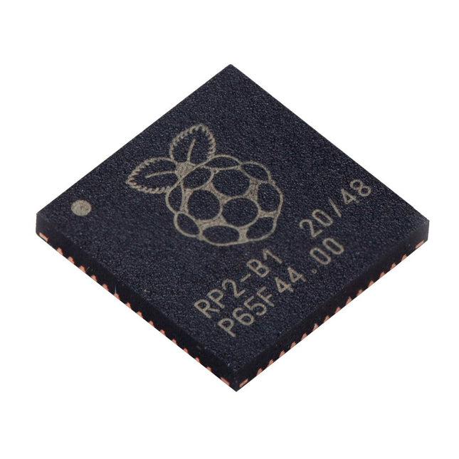
Dual ARM Cortex-M0+ @ 133 MHz
264 kB on-chip SRAM in six independent banks
Support for up to 16 MB of off-chip Flash memory via dedicated QSPI bus
DMA controller
Fully-connected AHB crossbar
Interpolator and integer divider peripherals
On-chip programmable LDO to generate core voltage
2x on-chip PLLs to generate USB and core clocks
30x GPIO pins, 4 of which can be used as analogue inputs
Peripherals
2x UARTs
2x SPI controllers
2x I²C controllers
16x PWM channels
USB 1.1 controller and PHY, with host and device support
8x PIO state machines
What you'll get
10x bare RP2040 chips
The Red Pitaya (STEMlab) is a credit card-sized, open-source test and measurement board that can be used to replace most measurement instruments used in electronics laboratories. With a single click, the board can transform into a web-based oscilloscope, spectrum analyser, signal generator, LCR meter, Bode plotter, and microcontroller.
The Red Pitaya (STEMlab) can replace the many pieces of expensive measurement equipment found at professional research organisations and teaching laboratories. The device, that based on Linux, includes an FPGA, digital signal processing (DSP), dual core ARM Cortex processor, signal acquisition and generation circuitry, micro USB socket, microSD card slot, RJ45 socket for Ethernet connection, and USB socket – all powered from an external mains adaptor.
This book is an introduction to electronics. It aims to teach the principles and applications of basic electronics by carrying out real experiments using the Red Pitaya (STEMlab). The book includes many chapters on basic electronics and teaches the theory and use of electronic components including resistors, capacitors, inductors, diodes, transistors, and operational amplifiers in electronic circuits. Many fun and interesting Red Pitaya (STEMlab) experiments are included in the book. The book also makes an introduction to visual programming environment.
The book is written for college level and first year university students studying electrical or electronic engineering.
This bundle includes the Red Pitaya STEMlab 125-14 PRO Gen 2 Starter Kit and the new book "Experimenting with Red Pitaya STEMlab Gen 2".
The Red Pitaya STEMlab 125-14 PRO Gen 2 Starter Kit is a powerful and flexible platform for signal processing, data acquisition, and electronic measurement applications. Designed for engineers, developers, researchers, and educators, this kit provides everything required to start building advanced measurement and control systems.
At the core of the kit is the STEMlab 125-14 PRO Gen 2 board, an upgraded and ultra-lightweight development platform. Powered by the Xilinx Zynq-7010 SoC with 512 MB of RAM, it combines FPGA programmability with ARM processing power to enable high-performance instrumentation and custom signal-processing solutions.
The board offers 14-bit ADC and DAC resolution, a 125 MS/s sampling rate, an input range of ±20 V, and up to 60 MHz bandwidth. Its improved low-noise analog front-end, USB-C connectivity, and compact design make it suitable for demanding applications such as RF development, radar systems, photonics research, software-defined radio (SDR), and industrial automation.
The Starter Kit includes all essential accessories for immediate use: a microSD card with preinstalled operating system, power supply, Ethernet cable for remote access, two 100 MHz oscilloscope probes, and SMA-to-BNC adapters for flexible signal connections.
The Red Pitaya STEMlab 125-14 PRO Gen 2 Starter Kit is an excellent platform for rapid prototyping, FPGA development, measurement instrumentation, and advanced electronics experimentation.
Features
14-bit ADC and DAC resolution
125 MS/s sampling rate
±20 V input range
Up to 60 MHz bandwidth
Xilinx Zynq-7010 SoC (FPGA + ARM processor)
512 MB RAM
Low-noise analog front- and back-ends
Applications
RF development and testing
Radar and wireless systems
Software-defined radio (SDR)
Photonics and optical research
Industrial automation and control systems
Signal analysis and instrumentation
Rapid prototyping of electronic measurement systems
Specifications
Processor
Dual-core ARM Cortex-A9
FPGA
AMD Xilinx Zynq-7010 SoC
RAM
512 MB (4 Gb)
Storage
microSD card (up to 32 GB)
Operating System
Linux-based Red Pitaya OS
ADC Resolution
14-bit
DAC Resolution
14-bit
Bandwidth
60 MHz (DC)
Sampling Rate
125 MS/s
Analog Input Channels
2
Analog Output Channels
2
Input Voltage Range
±1 V (LV) / ±20 V (HV)
Input Impedance
1 MΩ / 10 pF
Output Voltage Range
±1 V
Ethernet
1x Gigabit Ethernet (RJ45)
USB
2x USB-C 2.0 (for power and console)
Digital I/O
16x GPIO (3.3 V)
Communication Interfaces
I²C, SPI, UART, CAN
Power Supply
5 V/3 A via USB-C
Dimensions
106.8 x 60.0 x 17.9 mm
Included
1x Red Pitaya STEMlab 125-14 PRO Gen 2 board
2x 100 MHz oscilloscope probes
2x SMA-to-BNC adapters
1x microSD card with preinstalled OS
1x USB-C Power supply
1x Ethernet cable
Downloads
Documentation
Schematics
Book: Experimenting with Red Pitaya STEMlab Gen 2
With this new book, Red Pitaya goes beyond a versatile board. It becomes a powerful laboratory instrument for precision measurement, analysis, and control.
From the fundamentals of electronic project development, monitoring, control, and design to testing, this book walks you step-by-step through everything you need to know to harness the full potential of Red Pitaya hardware and software.
The book presents real-time, FPGA-based projects that are developed on a PC using the Vivado environment, then transferred to the Red Pitaya for execution and testing.
You will learn about enhanced performance, expanded I/O capabilities, improved FPGA features, and advanced connectivity options that open up new frontiers for precision measurement, monitoring, and control in your embedded applications.
Inside the book you will discover:
A deep dive into Red Pitaya architecture and hardware design
Electronic experiments using Red Pitaya for measurement and monitoring
Hands-on projects using the Python programming language
Practical guidance for FPGA programming using Red Pitaya
Red Pitaya FPGA projects using the Verilog HDL under Vivado IDE
Practical design of electronic projects including measurement and testing
Step-by-step examples that bridge theory and real-world implementation
Whether you are designing your own electronic circuits, developing signal analysis tools, or creating real-time control or monitoring systems, this book provides you the knowledge and confidence you need to fully learn and customize the Red Pitaya platform.
A Hands-on Guide to Crafting Your Own Power Plant
The book you are about to read provides a step-by-step guide for building a renewable energy power plant at home. Our goal was to make the book as practical as possible. The material is intended for immediate application with a small amount of theory. Yet, the theory is important as a foundation that saves time and effort by disabusing the readers of potential misconceptions. Specifically, upon having a firm understanding of photovoltaic physics, you will not be inclined to fruitlessly search for 90% efficient solar panels!
We want our readers to be the “doers”. If the book gets covered in grime and some pages become torn while you are building your power plant – this is the best compliment to us. The book covers solar and wind energy. Also, a curious power source based on manure is discussed as well, giving the doers an opportunity to further develop the manure fuel cell.
It is important to note that there are many companies offering installation of complete solar solutions. Upon installing the panels, the system is not owned by the customer. Therefore, there is no freedom for experimentation and optimization. Also, none can beat the cost of a DIY solution as well as the ultimate satisfaction.
All that is written here is a result of us building a renewable energy solution in Southern California. As the book was completed, the energy began flowing!
A Hands-on Guide to Crafting Your Own Power Plant
The book you are about to read provides a step-by-step guide for building a renewable energy power plant at home. Our goal was to make the book as practical as possible. The material is intended for immediate application with a small amount of theory. Yet, the theory is important as a foundation that saves time and effort by disabusing the readers of potential misconceptions. Specifically, upon having a firm understanding of photovoltaic physics, you will not be inclined to fruitlessly search for 90% efficient solar panels!
We want our readers to be the “doers”. If the book gets covered in grime and some pages become torn while you are building your power plant – this is the best compliment to us. The book covers solar and wind energy. Also, a curious power source based on manure is discussed as well, giving the doers an opportunity to further develop the manure fuel cell.
It is important to note that there are many companies offering installation of complete solar solutions. Upon installing the panels, the system is not owned by the customer. Therefore, there is no freedom for experimentation and optimization. Also, none can beat the cost of a DIY solution as well as the ultimate satisfaction.
All that is written here is a result of us building a renewable energy solution in Southern California. As the book was completed, the energy began flowing!
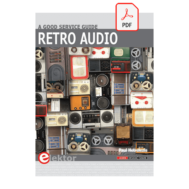
The intention of this book is to offer the reader understandings, ideas and solutions from the perspective of a workbench technician and electronics hobbyist. It is a descriptive text with many tables of useful data, servicing tips and supplementary notes of not so common knowledge.
Today there is a re-emerging, nostalgic interest in vinyl records and associated music entertainment gear. With this interest, there is a paralleled market for the repair of this gear.
This ‘hands-on’ servicing guide opens with fundamental considerations of the work space of repair and servicing. This includes a comprehensive discussion of essential test equipment and tools. Two chapters are devoted to obtaining servicing information about repair and obtaining spare parts. A key chapter is on general diagnosis and testing and includes the discussion of resistance, capacitance and inductance. These electrical properties are regularly in the mind of the repairer, so understanding of them is a key objective of this book. The next chapter is about time saving repair techniques and ensuring quality repair. The remaining chapters discuss entertainment equipment itself. Each of the chapters begins with an orderly discussion of the theory of operation and common and not so common problems specific to the equipment. All chapters conclude with a summary.
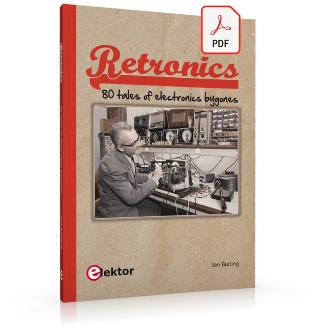
Quite unintentionally a one-page story on an old Heathkit tube tester in the December 2004 edition of Elektor magazine spawned dozens of ‘Retronics’ tales appearing with a monthly cadence, and attracting a steady flow of reader feedback and contributions to the series. Since launching his Retronics columns, Elektor Editor Jan Buiting has never been short of copy to print, or vintage equipment to marvel at.
This book is a compilation of about 80 Retronics installments published between 2004 and 2012. The stories cover vintage test equipment, prehistoric computers, long forgotten components, and Elektor blockbuster projects, all aiming to make engineers smile, sit up, object, drool, or experience a whiff of nostalgia.
To reflect that our memories are constantly playing tricks on us, and honoring that “one man’s rubbish is another man’s gem”, the tales in the book purposely have no chronological order, and no bias in favor of transistor or tube, microprocessor or discrete part, audio or RF, DIY or professional, dry or narrative style.
Although vastly diff erent in subject matter, all tales in the book are told with personal gusto because Retronics is about sentiment in electronics engineering, construction and repair, be it to reminisce about a 1960s Tektronix scope with a cleaning lady as a feature, or a 1928 PanSanitor box for dubious medical use.
Owners of this book are advised to not exceed one Retronics tale per working day, preferably consumed in the evening hours under lamp light, in a comfortable chair, with a piece of vintage electronic equipment close and powered up.
RFID technology has conquered many areas in which barcodes, magnetic strips and contact smartcards were used previously. Everyday applications, such as electronic ticketing, access cards, debit cards and electronic identity documents would not be possible without this technology.
MIFARE is the most widely used RFID technology, and this book provides a practical and comprehensive introduction to it. Among other things, the initial chapters cover physical fundamentals, relevant standards, RFID antenna design, security considerations and cryptography.
The complete design of a reader’s hardware and software is described in detail. The reader’s firmware and the associated PC software support programming using any .NET language. The specially developed PC program, “Smart Card Magic.NET”, is a simple development environment that supports sending commands to a card at the click of a mouse, as well as the ability to create C# scripts. Alternatively, one may follow all of the examples using Visual Studio 2010 Express Edition.
Finally, the major smart card reader API standards are introduced. The focus is on programming contactless smartcards using standard PC/SC readers using C/C++, Java and C#.
Highlights
Output Frequency (Sine): 50 MHz
Output Frequency (Square): 15 MHz
Channels: 2
Arbitrary Waveform Length: 16 Mpts
Features
Unique SiFi II (Signal Fidelity II) technology: generate the arbitrary waveforms point by point; recover the signal without distortion; sample rate accurate and adjustable; jitter of all the output waveforms (including Sine, Pulse, etc.) as low as 200 ps
16 Mpts memory depth per channel for arbitrary waveforms
Standard dual-channel with the same performance, equivalent to two independent signal sources
High frequency stability: ±1 ppm; low phase noise: -105 dBc/Hz
Built-in high-order harmonic generator (at most 8-order harmonics)
Built-in 7 digits/s, 240 MHz bandwidth full featured frequency counter
Up to 160 built-in arbitrary waveforms, covering the common signals in engineering application, medical electronics, auto electronics, math processing, and other various fields
Sample rate up to 250 MSa/s, vertical resolution 16 bits
Arbitrary waveform sequence editing function available; arbitrary waveforms also can be generated through the PC software
Various analog and digital modulation functions: AM, FM, PM, ASK, FSK, PSK, and PWM.
Standard waveform combine function, capable of outputting specified waveforms combined with the basic waveforms
Standard channel tracking function, when enabled, all the parameters of both channels are updated based on users' configurations
Standard interface: USB Host&Device and LAN (LXI Core 2011 Device); USB-GPIB function supported
4.3'' TFT
Included
1x Rigol DG2052 Function/Arbitrary Waveform Generator
1x Power cord
1x USB cable
Highlights
Output Frequency (Sine): 70 MHz
Output Frequency (Square): 20 MHz
Channels: 2
Arbitrary Waveform Length: 16 Mpts
Features
Unique SiFi II (Signal Fidelity II) technology: generate the arbitrary waveforms point by point; recover the signal without distortion; sample rate accurate and adjustable; jitter of all the output waveforms (including Sine, Pulse, etc.) as low as 200 ps
16 Mpts memory depth per channel for arbitrary waveforms
Standard dual-channel with the same performance, equivalent to two independent signal sources
High frequency stability: ±1 ppm; low phase noise: -105 dBc/Hz
Built-in high-order harmonic generator (at most 8-order harmonics)
Built-in 7 digits/s, 240 MHz bandwidth full featured frequency counter
Up to 160 built-in arbitrary waveforms, covering the common signals in engineering application, medical electronics, auto electronics, math processing, and other various fields
Sample rate up to 250 MSa/s, vertical resolution 16 bits
Arbitrary waveform sequence editing function available; arbitrary waveforms also can be generated through the PC software
Various analog and digital modulation functions: AM, FM, PM, ASK, FSK, PSK, and PWM.
Standard waveform combine function, capable of outputting specified waveforms combined with the basic waveforms
Standard channel tracking function, when enabled, all the parameters of both channels are updated based on users' configurations
Standard interface: USB Host&Device and LAN (LXI Core 2011 Device); USB-GPIB function supported
4.3'' TFT
Included
1x Rigol DG2072 Function/Arbitrary Waveform Generator
1x Power cord
1x USB cable
Highlights
Output Frequency (Sine): 100 MHz
Output Frequency (Square): 25 MHz
Channels: 2
Arbitrary Waveform Length: 16 Mpts
Features
Unique SiFi II (Signal Fidelity II) technology: generate the arbitrary waveforms point by point; recover the signal without distortion; sample rate accurate and adjustable; jitter of all the output waveforms (including Sine, Pulse, etc.) as low as 200 ps
16 Mpts memory depth per channel for arbitrary waveforms
Standard dual-channel with the same performance, equivalent to two independent signal sources
High frequency stability: ±1 ppm; low phase noise: -105 dBc/Hz
Built-in high-order harmonic generator (at most 8-order harmonics)
Built-in 7 digits/s, 240 MHz bandwidth full featured frequency counter
Up to 160 built-in arbitrary waveforms, covering the common signals in engineering application, medical electronics, auto electronics, math processing, and other various fields
Sample rate up to 250 MSa/s, vertical resolution 16 bits
Arbitrary waveform sequence editing function available; arbitrary waveforms also can be generated through the PC software
Various analog and digital modulation functions: AM, FM, PM, ASK, FSK, PSK, and PWM.
Standard waveform combine function, capable of outputting specified waveforms combined with the basic waveforms
Standard channel tracking function, when enabled, all the parameters of both channels are updated based on users' configurations
Standard interface: USB Host&Device and LAN (LXI Core 2011 Device); USB-GPIB function supported
4.3'' TFT
Included
1x Rigol DG2102 Function/Arbitrary Waveform Generator
1x Power cord
1x USB cable
Specifications
Channels: 3
Total Power: 195 Watts
Max. Voltage: 30 Volts
Max. Current: 3 Amps
Low ripple and noise: <350 μVrms/2 mVpp
Excellent linear regulation rate and load regulation rate
Fast transient response time: <50 μs
Some channels are isolated
Standard OVP/OCP/OTP protection functions
Standard timing output
Built-in V,A,W measurements and waveform display
Independent control for each channel
3.5 inch TFT display
Included
1x Rigol DP832 DC Power Supply
1x Power cord
1x USB cable
Specifications
Bandwidth: 50 MHz
Analog Channels: 4
Real-time sample rate up to 1 GS/s
Memory depth up to 24 Mpts
Up to 30,000 wfms/s waveform capture rate
Up to 60,000 frames hardware real-time waveform recording and playback functions
Innovative 'UltraVision' technology
Various trigger and bus decoding functions
Low noise floor, vertical scale range: 1 mV/div to 10 V/div
Various interfaces: USB Host&Device, LAN (LXI), AUX
Compact size, light weight, easy to use
7 inch WVGA (800x480) TFT LCD, intensity graded color display
Included
1x Rigol DS1054Z Oscilloscope
1x Power cord
1x USB cable
4x PVP2150 Passive oscilloscope probe (150 MHz)
Specifications
Bandwidth: 200 MHz
Analog Channels: 2
Real-time sample rate up to 1 GS/s
Memory depth up to 24 Mpts
Up to 30,000 wfms/s waveform capture rate
Up to 60,000 frames hardware real-time waveform recording and playback functions
Innovative 'UltraVision' technology
Various trigger and bus decoding functions
Low noise floor, vertical scale range: 1 mV/div to 10 V/div
Various interfaces: USB Host&Device, LAN (LXI), AUX
Compact size, light weight, easy to use
7 inch WVGA (800x480) TFT LCD, intensity graded color display
Included
1x Rigol DS1202Z-E Oscilloscope
1x Power cord
1x USB cable
2x PVP2350 passive oscilloscope probe (350 MHz)
With the availability of free and open source C/C++ compilers today, you might wonder why someone would be interested in assembler language. What is so compelling about the RISC-V Instruction Set Architecture (ISA)? How does RISC-V differ from existing architectures? And most importantly, how do we gain experience with the RISC-V without a major investment? Is there affordable hardware available?
The availability of the Espressif ESP32-C3 chip provides a way to get hands-on experience with RISC-V. The open sourced QEMU emulator adds a 64-bit experience in RISC-V under Linux. These are just two ways for the student and enthusiast alike to explore RISC-V in this book.
The projects in this book are boiled down to the barest essentials to keep the assembly language concepts clear and simple. In this manner you will have “aha!” moments rather than puzzling about something difficult. The focus in this book is about learning how to write RISC-V assembly language code without getting bogged down. As you work your way through this tutorial, you’ll build up small demonstration programs to be run and tested. Often the result is some simple printed messages to prove a concept. Once you’ve mastered these basic concepts, you will be well equipped to apply assembly language in larger projects.
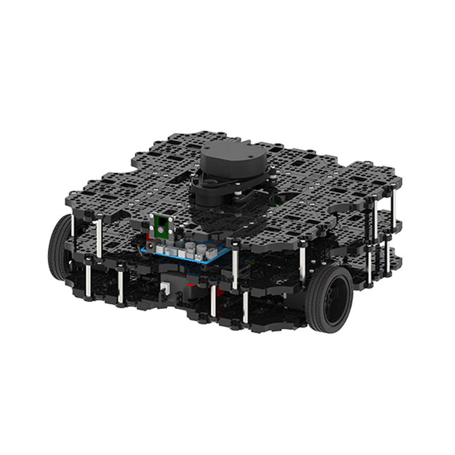
World’s Most Popular ROS Platform TurtleBot is the most popular open source robot for education and research. The new generation TurtleBot3 is a small, low cost, fully programmable, ROS based mobile robot. It is intended to be used for education, research, hobby and product prototyping. Affordable Cost TurtleBot was developed to meet the cost-conscious needs of schools, laboratories and companies. TurtleBot3 is the most affordable robot among the SLAM-able mobile robots equipped with a 360° Laser Distance Sensor LDS-01. ROS Standard The TurtleBot brand is managed by Open Robotics, which develops and maintains ROS. Nowadays, ROS has become the go-to platform for all the roboticists around the world. TurtleBot can be integrated with existing ROS-based robot components, but TurtleBot3 can be an affordable platform for whom want to get started learning ROS. Extensibility TurtleBot3 encourages users to customize its mechanical structure with some alternative options: open source embedded board (as a control board), computer and sensors. TurtleBot3 Waffle Pi is a two-wheeled differential drive type platform but it is able to be structurally and mechanically customized in many ways: Cars, Bikes, Trailers and so on. Extend your ideas beyond imagination with various SBC, sensors and motors on a scalable structure. Modular Actuator for Mobile Robot TurtleBot3 is able to get a precise spatial data by using 2 DYNAMIXEL’s in the wheel joints. DYNAMIXEL XM series can be operated by one of 6 operating modes (XL series: 4 operating modes): Velocity control mode for wheels, Torque control mode or Position control mode for joint, etc. DYNAMIXEL can be used even to make a mobile manipulator which is light but can be precisely controlled with velocity, torque and position control. DYNAMIXEL is a core component that makes TurtleBot3 perfect. It is easy to assemble, maintain, replace and reconfigure. Open Control Board for ROS The control board is open-sourced in hardware wise and in software wise for ROS communication. The open source control board OpenCR1.0 is powerful enough to control not only DYNAMIXEL’s but also ROBOTIS sensors that are frequently being used for basic recognition tasks in cost effective way. Various sensors such as Touch sensor, Infrared sensor, Color sensor and a handful more are available. The OpenCR1.0 has an IMU sensor inside the board so that it can enhance precise control for countless applications. The board has 3.3 V, 5 V, 12 V power supplies to reinforce the available computer device lineups. Open Source The hardware, firmware and software of TurtleBot3 are open source which means that users are welcomed to download, modify and share source codes. All components of TurtleBot3 are manufactured with injection molded plastic to achieve low cost, however, the 3D CAD data is also available for 3D printing. Specifications Maximum translational velocity 0.26 m/s Maximum rotational velocity 1.82 rad/s (104.27 deg/s) Maximum payload 30 kg Size (L x W x H) 281 x 306 x 141 mm Weight (+ SBC + Battery + Sensors) 1.8 kg Threshold of climbing 10 mm or lower Expected operating time 2h Expected charging time 2h 30m SBC (Single Board Computers) Raspberry Pi 4 (2 GB RAM) MCU 32-bit ARM Cortex-M7 with FPU (216 MHz, 462 DMIPS) Remote Controller RC-100B + BT-410 Set (Bluetooth 4, BLE) Actuator XL430-W210 LDS (Laser Distance Sensor) 360 Laser Distance Sensor LDS-01 or LDS-02
Camera Raspberry Pi Camera Module v2.1 IMU Gyroscope 3 AxisAccelerometer 3 Axis Power connectors 3.3 V/800 mA5 V/4 A12 V/1 A Expansion pins GPIO 18 pinsArduino 32 pin Peripheral 3x UART, 1x CAN, 1x SPI, 1x I²C, 5x ADC, 4x 5-pin OLLO DYNAMIXEL ports 3x RS485, 3x TTL Audio Several programmable beep sequences Programmable LEDs 4x User LED Status LEDs 1x Board status LED1x Arduino LED1x Power LED Buttons and Switches 2x Push buttons, 1x Reset button, 2x Dip switch Battery Lithium polymer 11.1 V 1800 mAh / 19.98 Wh 5C PC connection USB Firmware upgrade via USB / via JTAG Power adapter (SMPS) Input: 100-240 VAC 50/60 Hz, 1.5 A @maxOutput: 12 VDC, 5 A Downloads ROS Robot Programming GitHub E-Manual Community