Products
-

OWON OWON HDS272S 2-ch Oscilloscope (70 MHz) + Multimeter + Signal Generator
Oscilloscope, multimeter and waveform generator in the same battery-powered device, to work on the go. Features Oscilloscope + multimeter + waveform generator, multifunction in one 3.5-inch high-resolution, high-contrast colour LCD display, suitable for outdoor use 18650 lithium battery, comprehensive power consumption ≤3 W, can work continuously for about 6 hours USB-C interface, support power bank, support PC software connection Self-calibration function SCPI supported, facilitate secondary development Specifications Oscilloscope Bandwidth 70 MHz Channels 2-ch Oscilloscope + 1-ch Generator Sample Rate 250 MSa/s Acquisition Model Normal, Peak detect Record Length 8K Display 3.5-inch LCD Waveform Refresh Rate 10,000 wfrms/s Input Coupling DC, AC, and Ground Input Impedance 1 MΩ ±2%, in parallel with 16pF±10pF Probe Attenuation Factors 1X,10X,100X,1000X,10000X Max. input Voltage 400 V (DC+AC, PK-PK, 1MΩ input impedance) (10:1 probe attenuation) Bandwidth Limit (typical) 20 MHz Horizontal Scale 5 ns/div - 1000 s/div, step by 1 - 2 - 5 Vertical Sensitivity 10 mV/div - 10 V/div Vertical Resolution 8 bits Trigger Type Edge Trigger Modes Auto, Normal, single Automatic Measurement Period, Frequency, Mean, PK-PK, Max, Min Cursor Measurement ΔV, ΔT, ΔT& ΔV between cursors Communication Interface USB Type-C Multimeter Max. Resolution 20,000 counts Testing Mode Voltage, Current, Resistance, Capacitance, Diode, and Continuity test Input Impedance 10 MΩ Max Input Voltage AC: 750 V | DC: 1000 V Max Input Current DC: 10 A | AC: 10 A Diode 0-2 V Waveform Generator Frequency Output Sine 0.1 Hz - 25 MHz Square 0.1 Hz - 5 MHz Ramp 0.1 Hz - 1 MHz Pulse 0.1 Hz - 5 MHz Arbitrary 0.1 Hz - 5 MHz Sampling Rate 125 MSa/s Channel 1-ch Amplitude Range 20 mVpp - 5 Vpp Waveform Length 8K Vertical Resolution 14 bits Output Impedance 50Ω Downloads User Manual for HDS200 Series SCPI Protocol for HDS200 Series Quick Guide for HDS200 Series PC Software for OWON HDS200 Series
€ 199,65
-

OWON OWON OW18B True RMS Multimeter
Features Data-logger & Multimeter & Thermometer 3 (5/6) digits True RMS test supported BLE 4.0 wireless transmission, more stable, less power consumption Chart and Diagram mode, to analyze your data Supports NCV Voice Broadcast simplifies testing Flashlight function Built-in offline recording function Supports Android, iOS Included Test leads K-type thermocouple 9 V Battery Bolt driver Crocodile clip Quick guide
€ 39,63
-

OWON OWON OW18E True RMS Multimeter
Features 4 1/2 bit resolution (20000 Counts) Data Logger Multimeter Thermometer True RMS test supported BLE 4.0 wireless transmission, more stable,less power consumption Build-in offline record function Chart and Diagram mode helps to analyze the data tendency Flashlight function lightens the darkness Support NCV non-contact voltage sense Widely supported on Android, iOS, Windows Included OWON OW18E Multimeter Quick Guide Multimeter Lead K-type Thermocouple Bolt Driver App Download The Bluetooth function of this multimeter is compatible with Android-app version 1.5.8.0 or newer. Use the QR code in the box or go to http://files.owon.com.cn/bluetooth.
€ 59,95
-

OWON OWON P4603 DC Power Supply (180 W)
This OWON DC Power Supply has a small body and is easy to carry due to its light weight. Featuring a 3.7" TFT LCD display, it has a maximum output power of 180 W and a resolution of 1 mV/1 mA. Features Channel Single Channel Output Total Output Power 180 W Channel Output 0 - 60 V / 0 - 3 A × 1-CH Display 3.7' color LCD display Dimension 117 mm(L) × 194 mm(H) × 295 mm(D) Weight Approx. 5.8 kg Interface RS232 Specifications Rated Output (0 ℃ - 40 ℃) Voltage 0 - 60 V Current 3 A Load Regulation Voltage ≤ 0.01% + 3 mV Current ≤ 0.01% + 3 mA Power Regulation Voltage ≤ 0.01% + 3 mV Current ≤ 0.01% + 3 mA Setting Resolution Voltage 1 mV Current 1 mA Readback Resolution Voltage 1 mV Current 1 mA Setpoint accuracy (within 12 months) (25 ℃ ± 5 ℃) Voltage ≤ 0.03% + 10 mV Current ≤ 0.1% + 5 mA Readback Resolution (25 ℃ ± 5 ℃) Voltage ≤ 0.03% + 10 mV Current ≤ 0.1% + 5 mA Ripple/Noise (20 Hz - 20 MHz) Voltage (Vp-p) ≤ 4 mVp-p Voltage (Vrms) ≤ 1 mVrms Current (rms) ≤ 4 mArms Output temperature coefficient(0 ℃ - 40 ℃) Voltage ≤ 0.03% + 10 mV Current ≤ 0.1% + 5 mA Readback temperature coefficient Voltage ≤ 0.03% + 10 mV Current ≤ 0.1% + 5 mA Response Time 100 μs Storage 5 groups of data Working Temperature 0 - 40 ℃
€ 164,57
-

OWON OWON SDS1104 4-ch Oscilloscope (100 MHz)
Specifications Bandwidth 100 MHz Sample Rate 100 MS/s Horizontal Scale (s/div) 5ns/div - 1000s/div, step by 1 - 2 - 5 Channel 4 Display 7" color LCD, 800 x 480 pixels Input Coupling DC, AC and GND Vertical Resolution (A/D) Vertical Resolution (A/D) Vertical Sensitivity 5mV/div - 5V/div (at input) Trigger Type Edge, Video Trigger Mode Auto, Normal and Single Waveform Math +, -, x, ÷, invert, FFT Fuse 2A, T class, 250 V Dimension (W x H x D) 301 x 152 x 70 mm Weight 1.1 kg Included 1 x SDS1104 1 x Mains power cord 1 x CD Rom 1 x Quickstart Guide 1 x USB Cable 4 x Oscilloscope probe 1 x Probe Adjust For more information, check out the user manual here.
€ 249,00
-

OWON OWON SPE6103 DC Power Supply (300 W)
The OWON SPE6103 is a 1-channel DC power supply (300 W) in a small body with features like over voltage and over current protection. It has a high resolution of 10 mV/1 mA. The 2.8" LCD displays the following information (constant voltage output, constant current output, cumulative running time, actual output power, channel output status, actual voltage output, actual current output). Features Small body for easy carry High resolution: 10 mV/1 mA List waveform editing output, editable 10 groups of timing output function Low ripple/noise Over voltage / over current protection Output voltage and current curve monitoring function Intelligent temperature control fan cooling 2.8-inch TFT LCD display USB communication interface, support SCPI Specifications Model SPE6102 SPE6103 Rated Output (0-40°C) Voltage 0-60 V 0-60 V Current 10 A 10 A Output Power 200 W 300 W USB Output 5 V/1 A (SPE Series) or suppout QC2.0, QC3.0, BC1.2, Apple, Huawei, Samsung fast charging protocols (optional) Load Regulation Voltage ≤30 mV Current ≤20 mA Power Regulation Voltage ≤30 mV Current ≤20 mA Setting Resolution Voltage 10 mV Current 1 mA Readback Resolution Voltage 10 mV Current 1 mA Value Resolution (within 12 months) (25 ±5°C) Voltage ≤0.1% ±30 mV ≤0.1% ±30 mV Current ≤0.05% ±10 mA Readback Value Resolution (25 ±5°C) Voltage ≤0.1% ±30 mV ≤0.1% ±30 mV Current Ripple/Noise Voltage (Vp-p) ≤50mVp-p ≤50mVp-p Voltage (rms) ≤5mVrms ≤5mVrms Current (rms) ≤30mAp-p Output temperature coefficient (0-40°C) Voltage 100ppm/°C Current 200ppm/°C Readback temperature coefficient Voltage 100ppm/°C Current 200ppm/°C Response Time (50-100% rated load) ≤1.0ms Storage 4 groups of data Working Temperature 0-40°C Included 1x OWON SPE6102 1x Power Cord 1x Quick Guide 1x USB Cable 1x Fuse Downloads User Manual Programming Manual Software
€ 125,00
-

OWON OWON SPS3081 Fanless DC Power Supply (120 W)
The OWON SPS3081 Fanless Programmable DC Power Supply (120 W) delivers ultra-quiet, high-precision performance with 10 mV/1 mA accuracy and advanced heat dissipation for long-term reliability. Featuring comprehensive protection, a USB interface with SCPI support for remote control, and a 2.8-inch TFT LCD screen, it is the perfect choice for laboratories, electronics testing, and research. Features Fanless design: Ultra-quiet operation, reducing vibration noise and minimizing the potential failure risks associated with traditional cooling fans. Excellent heat dissipation design: Ensures a controlled temperature rise, allowing long-term operation under full load conditions and extending internal component longevity. Lightweight and ultra-thin design. Output accuracy up to 10 mV/1 mA. Supports List waveform editing and output, with four memory shortcut parameters for quick and convenient access. Integrated protection features include overvoltage, overcurrent, overtemperature, and input undervoltage protection for enhanced safety. Built-in discharge circuit prevents residual high voltage risks when the power is turned off. USB communication interface with SCPI protocol support, enabling PC programming and remote control for simplified user management. 2.8-inch TFT LCD screen Specifications Model SPS6051 SPS3081 Rated Output (0°C-40°C) Voltage 0-61 V 0-31 V Current 0-5.1 A 0-8.1 A Power 150 W 120 W Load Regulation Voltage ≤30 mV Current ≤20 mA Power Regulation Voltage ≤30 mV Current ≤20 mA Setting Resolution Voltage 10 mV Current 1 mA Readback Resolution Voltage 10 mV Current 1 mA Seting Accuracy (25°C ±5°C) Voltage ≤0.05% ±20 mV ≤0.1% ±20 mV Current ≤0.05% ±20 mA ≤0.2% ±20 mA Readback Accuracy (25°C ±5°C) Current ≤0.05% ±20 mV ≤0.1% ±20 mV Voltage ≤0.05% ±20 mV ≤0.2% ±20 mA Ripple/Noise Voltage ≤30 mVp-p ≤30 mVp-p Voltage ≤4 mVrms ≤5 mVrms Current ≤10 mAp-p ≤30 mAp-p Output temperature coefficient (0°C-40°C) Voltage 100 ppm/°C Current 200 ppm/°C Readback temperature coefficient Voltage 100 ppm/°C Current 200 ppm/°C Response Time (50-100% rated load) ≤1.0 ms Storage 4 groups of data Working Temperature 0-40°C Display 2.8-inch color LCD display Interface USB Dimensions (W x H x D) 82 x 142 x 226 mm Weight 1.8 kg Included 1x OWON SPS3081 Power Supply 2x Test leads 1x Power cord 1x Manual Downloads Datasheet User Manual Programming Manual PC Software
€ 137,94
-

OWON OWON SPS6051 Fanless DC Power Supply (150 W)
The OWON SPS6051 Fanless Programmable DC Power Supply (150 W) delivers ultra-quiet, high-precision performance with 10 mV/1 mA accuracy and advanced heat dissipation for long-term reliability. Featuring comprehensive protection, a USB interface with SCPI support for remote control, and a 2.8-inch TFT LCD screen, it is the perfect choice for laboratories, electronics testing, and research. Features Fanless design: Ultra-quiet operation, reducing vibration noise and minimizing the potential failure risks associated with traditional cooling fans. Excellent heat dissipation design: Ensures a controlled temperature rise, allowing long-term operation under full load conditions and extending internal component longevity. Lightweight and ultra-thin design. Output accuracy up to 10 mV/1 mA. Supports List waveform editing and output, with four memory shortcut parameters for quick and convenient access. Integrated protection features include overvoltage, overcurrent, overtemperature, and input undervoltage protection for enhanced safety. Built-in discharge circuit prevents residual high voltage risks when the power is turned off. USB communication interface with SCPI protocol support, enabling PC programming and remote control for simplified user management. 2.8-inch TFT LCD screen Specifications Model SPS6051 SPS3081 Rated Output (0°C-40°C) Voltage 0-61 V 0-31 V Current 0-5.1 A 0-8.1 A Power 150 W 120 W Load Regulation Voltage ≤30 mV Current ≤20 mA Power Regulation Voltage ≤30 mV Current ≤20 mA Setting Resolution Voltage 10 mV Current 1 mA Readback Resolution Voltage 10 mV Current 1 mA Seting Accuracy (25°C ±5°C) Voltage ≤0.05% ±20 mV ≤0.1% ±20 mV Current ≤0.05% ±20 mA ≤0.2% ±20 mA Readback Accuracy (25°C ±5°C) Current ≤0.05% ±20 mV ≤0.1% ±20 mV Voltage ≤0.05% ±20 mV ≤0.2% ±20 mA Ripple/Noise Voltage ≤30 mVp-p ≤30 mVp-p Voltage ≤4 mVrms ≤5 mVrms Current ≤10 mAp-p ≤30 mAp-p Output temperature coefficient (0°C-40°C) Voltage 100 ppm/°C Current 200 ppm/°C Readback temperature coefficient Voltage 100 ppm/°C Current 200 ppm/°C Response Time (50-100% rated load) ≤1.0 ms Storage 4 groups of data Working Temperature 0-40°C Display 2.8-inch color LCD display Interface USB Dimensions (W x H x D) 82 x 142 x 226 mm Weight 1.8 kg Included 1x OWON SPS6051 Power Supply 2x Test leads 1x Power cord 1x Manual Downloads Datasheet User Manual Programming Manual PC Software
€ 134,31
-

OWON OWON VDS1022I 2-ch USB Oscilloscope (25 MHz)
OWON VDS1022I 2-channel USB oscilloscope (25 MHz) is a oscilloscope for use with a computer. It is powered by USB and has a small size, making it easy to take it with you. The oscilloscope is very economical. It has a shielded USB connection, reducing interference and protecting the computer against over-voltage. The multi port on the scope can be used for external triggering, trigger out or Pass / Fail output. Features 25 MHz bandwidth, and max 1 GS/s real-time sample rate 10M record length Friendly UI: FFT, or X-Y, and waveform 2 views displayed on the same screen Multi-trigger option: edge, video, slope, pulse, and alternate USB isolation – less signal inference, more PC protection USB bus powering, and LAN remote control (optional) Ultra-thin body design, easy portability Specifications Bandwidth 25 MHz Channel 2+1 (multi) Sample Rate 100 MSa/s Horizontal Scale (s/div) 5 ns/div~100s/div, step by 1~2~5 Record Length 5K Max Input Voltage 400 V (PK - PK) (DC+AC, PK - PK) 40 V (PK - PK) (DC+AC, PK - PK) Vertical Resolution (A/D) 8 bits (2 channels simultaneously) Model VDS1022I Vertical Sensitivity 5 mV/div~5 V/div Trigger Type Edge, Pulse, Video, Slope, and Alternate Trigger Mode Auto, Normal, and Single Acquisition Mode Sample, Peak Detect, and Average Waveform Math +, -, ×, ÷, invert, FFT Communication Interface USB 2.0 (isolation) Multi-function Interface Signal Type Level Standard TTL Power Supply 5.0 V/1 A Power Consumption ≤2.5 W Dimensions (W × H × D) 170 x 120 x 18 mm Weight 0.26 kg Included 1x OWON VDS1022I oscilloscope 1x CD-ROM 1x Quick start guide 2x Oscilloscope probe 1x Probe tool 1x Power adapter 1x USB cable 1x Silicone case protectors 1x Power cable Downloads Datasheet User manual SCPI protocol USB driver
€ 119,00
-
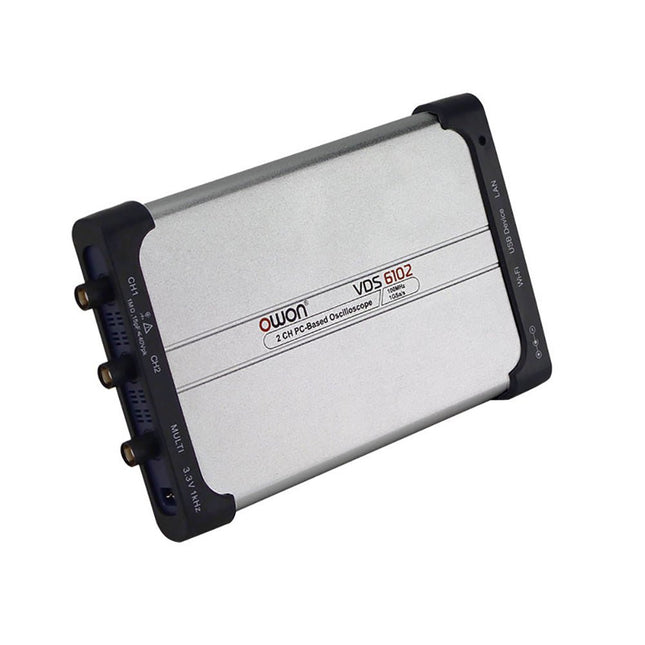
OWON OWON VDS6102A 2-ch USB Oscilloscope (100 MHz)
The OWON VDS6000 Series PC Oscilloscope combines powerful performance with a sleek, ultra-thin design. With 100 MHz bandwidth, 1 GSa/s real-time sampling, and up to 14-bit resolution, it delivers highly accurate measurements. The built-in 5 MHz function generator, USB-C power supply, and optional WiFi connectivity make it incredibly versatile. Compatible with Windows, Linux, Android, and iOS, the VDS6000 is perfect for labs, fieldwork, and remote diagnostics – compact, flexible, and ready for any challenge. Features Bandwidth: 100 MHz Vertical resolution: 14 bits Rise time: ≤3.5 ns Memory: 10 Mpts Number of channels: 2 channels + 1 channel function generator Horizontal scale: 5ns - 100s/div Sample rate: Max. 1 GSa/s Maximum voltage: 40 V (peak - peak) Automatic measurements: Vpp, Vavg, Vamp, Vrms, Freq, Period, Vmax, Vmin, Vtop, Vbase, Overshoot, Preshoot, Rise Time, Connectivity: USB-C, LAN, Wifi (optional) Fall Time, Delay A→B↑, Delay A→B↓, +Width, -Width, +Duty, -Duty Bandwidth: 5 MHz Sample rate: 25 MSa/s Standard waveforms: Sine (0.1 Hz - 5 MHz), Square (0.1 Hz - 200 kHz), Ramp (1 Hz - 10 kHz), Pulse (1 Hz - 10 kHz) Resolution: 10 bits DC offset range (AC + DC): ±2.5 V Amplitude range: 10 mVpp - 5 Vpp Dimensions: 190 x 120 x 18 mm Weight: 380 g Downloads Manual Quick Guide PC Software MacOS Software
€ 330,00
-

OWON OWON XDG2035 2-ch Arbitrary Waveform Generator (35 Mhz)
The 2-channel OWON XDG2035 is a function/waveform generator that can generate signals with a maximum frequency of 35 Hz. The generator has a resolution of 1 µHz and a sample rate of 500 MSa/s. The OWON XDG2035 is capable of generating 6 standard waveforms and 150 arbitrary waveforms. With the included software you can write advanced functions up to 10 million points. Waveforms can be saved to the function generator's internal memory using a PC via USB or LAN. The OWON XDG2035 also supports SCPI commands and LabView. The function generator has an integrated high-quality frequency counter, which can operate from 100 to 200 MHz. Features Max. 35 MHz frequency output 500 MSa/s Sample rate, Vertical resolution 1μHz 14 bits Vertical Resolution, 10 Marb waveform length Comprehensive waveform output: 6 basic waveforms,and 150 built-in arbitrary waveforms Comprehensive modulation functions: AM, FM, PM, FSK, 3FSK, 4FSK, PSK, OSK, ASK, BPSK, PWM, Sweep, and Burst High-accuracy frequency counter integrated, supported range 100-200 MHz SCPI and LabVIEW supported 7 inch multi-touch screen (800 x 480 pixels) Specifications Channel 2 Frequency Output 35 MHz Sample Rate 500 MSa/s Vertical Resolution 14 bits Waveform Standard Waveform sine, square, pulse, ramp, noise, and harmonic Arbitrary Waveform exponential rise, exponential fall, sin(x)/x, step wave, and others, total 150 built-in waveforms, and user-defined arbitrary waveform Frequency (resolution 1 μHz) Sine 1 μHz-100 MHz Square 1 μHz ~ 30 MHz Pulse 1 μHz ~ 25 MHz Ramp 1 μHz ~ 3 MHz Noise (-3 dB, typical) 100 MHz Arbitrary Waveform 1 μHz ~ 15 MHz Harmonic 1 μHz ~ 50 MHz Accuracy ±2ppm, 25°C ±5°C Waveform Length 2 points - 10M points Amplitude Into 50Ω load 1mVpp ~ 10Vpp (≤25 MHz); 1mVpp ~ 5Vpp (≤60 MHz); 1mVpp ~ 2.5Vpp (≤100 MHz) Modulation Type AM, DSB-AM, FM, PM, ASK, FSK, PSK, BPSK, QPSK, 3FSK, 4FSK, OSK, PWM, SUM Frequency Counter Function Frequency, period, +width, -width, +duty, and -duty Frequency Range 100 ~ 200 MHz Frequency Resolution 7 digits Input/Output Input mode frequency counter, external modulation input, external trigger input, internal clock output, external reference clock input/output Communication Interface USB Host, USB Device, LAN, RS232 (optional) Mechanical specifications Dimensions 340 x 177 x 90 mm Weight 2.3 kg Included 1x OWON XDG2035 1x Power Cord 1x CD-ROM 1x Quick start guide 1x USB Cable 1x BNC-BNC Cable Downloads Quick Guide
€ 339,00
-
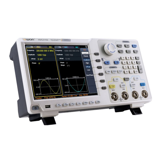
OWON OWON XDG3102 2-ch Arbitrary Waveform Generator (100 MHz)
Features Advanced DDS technology, up to 250 MHz frequency output 1.25 GS/s sampling rate, and 1 μHz frequency resolution Up to 1M arbitrary waveform length Vertical resolution: 14 bits Comprehensive waveform output: 6 groups waveforms, and 152 group built-in arbitrary waveforms Comprehensive modulation options: AM, FM, PM, FSK, 3FSK, 4FSK, PSK, OSK, ASK, BPSK, PWM, sweep, and burst High-accuracy frequency counter integrated, ranging from 100MHz till 200MHz SCPI and LabVIEW supported 8-inch 800 x 600 pixels touch screen LCD Specifications XDG3102 Channel 2 Frequency Output 100MHz Sample Rate 1.25GSa/s Vertical Resolution 14 bits Waveform Standard Waveform sine, square, pulse, ramp, noise, and harmonic Arbitrary Waveform exponential rise, exponential fall, sin(x)/x, step wave, and others, total of 150 built-in waveforms, and user-defined arbitrary waveform Frequency (resolution 1μHz) Sine 1μHz - 100MHz Square 1μHz - 40MHz Pulse 1μHz - 25MHz Ramp 1μHz - 5MHz Harmonic 1μHz - 50MHz Noise 120MHz (-3dB, typical) Arbitrary Waveform built-in waveform: 1uHz - 15MHzuser-defined waveform: 1uHz - 50MHz Accuracy ±1ppm, 0°C - 40°C Amplitude Amplitude (50Ω) 1mVpp - 10Vpp (≤40MHz); 1mVpp - 5Vpp (≤80MHz) 1mVpp - 2.5Vpp (≤120MHz); 1mVpp - 1Vpp (≤250MHz) Amplitude(high impedance) 2mVpp - 20Vpp (≤40MHz); 2mVpp - 10Vpp (≤80MHz); 2mVpp - 5Vpp (≤120MHz); 2mVpp - 2Vpp (≤250MHz) Resolution 1mV or 4 digits DC Offset Range (50Ω) ±(5 Vpk - Amplitude Vpp/2) Range (high-Z, open circuit) ±(10 Vpk - Amplitude Vpp/2) Accuracy ±(1% of |setting| + 1mV + Amplitude Vpp x 0.5%) Resolution 1mV or 4 digits Load Impedance 50Ω (typical) Accuracy ±(1% of setting + 1 mVpp) (typical, 1kHz sine, 0V offset) Sine Wave Spectrum Purity Harmonic Distortion Typical (0dB) DC - 1MHz: <-65dBc 1MHz - 10MHz: <-60dBc 10MHz - 120MHz: <-50dBc 120MHz - 200MHz: <-45dBc Total Harmonic Distortion <0.05 %, 10 Hz to 20 kHz, 1 Vpp Spurious (non-harmonic), Typical (0dB) ≤10MHz: <-70dBc >10MHz: <-70dBc + 6dB/ octave Phase Noise Typical (0 dBm, 10 kHz deviation) 10MHz: ≤-110dBc/Hz Square Rise/Fall Time <5ns Overshoot <3% Duty Cycle 50.0% (fixed) Jitter (rms) 300ps + 100ppm Pulse Pulse Width 12ns - 996875s Leading/Trailing Edge Time ≧7ns Overshoot <3% Jitter (rms) 300ps + 100ppm Ramp Linearity ≤1% of peak output (typical, 1kHz, 1 Vpp, 50% symmetry) Symmetry 0% to 100% Harmonic Harmonic Order ≤16 Harmonic Type even, odd, all, user Harmonic Amplitude could be set for all the harmonics Harmonic Phase Arbitrary Waveform Length 2 points - 1M points Vertical Resolution 14 bits Minimum Rise/Fall Time <7ns Jitter (rms) 3ns Modulation Type AM, FM, PM, PWM, FSK, 3FSK, 4FSK, PSK, OSK, ASK, BPSK, sweep, and burst AM Carrier Waveform sine, square, ramp, and arbitrary (except DC) Source internal / external Modulating Waveform sine, square, ramp, noise, and arbitrary Depth 0.0% - 100.0% Modulating Frequency 2 mHz - 100 kHz FM Carrier Waveform sine, square, ramp, and arbitrary (except DC) Source internal / external Modulating Waveform sine, square, ramp, noise, and arbitrary Modulating Frequency 2 mHz - 100 kHz PM Carrier Waveform sine, square, ramp, and arbitrary (except DC) Source internal / external Modulating Waveform sine, square, ramp, noise, and arbitrary Phase Deviation 0° - 180° Modulating Frequency 2 mHz - 100 kHz PWM Carrier Waveform pulse Source internal / external Modulating Waveform sine, square, ramp, noise, and arbitrary Width Deviation 0 ~ minimum (pulse duty ratio, 100% - pulse duty ratio) Modulating Frequency 2 mHz - 100 kHz FSK / 3FSK / 4FSK Carrier Waveform sine, square, ramp, and arbitrary (except DC) Source internal / external Modulating Waveform square with 50% duty cycle Key Frequency 2 mHz - 1MHz PSK Carrier Waveform sine, square, ramp, and arbitrary (except DC) Source internal / external Modulating Waveform square with 50% duty cycle Key Frequency 2 mHz - 1MHz OSK Carrier Waveform sine, square, ramp, and arbitrary (except DC) Source internal Oscillation Time square with 50% duty cycle Key Frequency 2 mHz - 1MHz ASK Carrier Waveform sine, square, ramp, and arbitrary (except DC) Source internal / external Modulating Waveform square with 50% duty cycle Key Frequency 2 mHz - 1MHz BPSK Carrier Waveform sine, square, ramp, and arbitrary (except DC) Source internal Modulating Waveform square with 50% duty cycle Key Frequency 2 mHz - 1MHz Sweep Carrier Waveform sine, square, ramp, and arbitrary (except DC) Type linear, and log Direction up, and down Sweep Time 1 ms to 500s, ± 0.1% Trigger Source internal, external, and manual Burst Carrier Waveform sine, square, ramp, pulse, and arbitrary (except DC) Burst Count 1 to 50,000 period, infinite, gating Internal Period 10 ns - 500 s Gated Source external trigger Frequency Counter Function frequency period, +width, -width, +duty, and -duty Frequency Range 100 MHz - 200 MHz Frequency Resolution 7 digits Input / Output Display 8”800 x 600 pixels touch screen LCD Type frequency counter, external modulation input,external trigger input,external reference clock input / output Communication Interface USB Host, USB Device, and LAN Dimension 340 x 177 x 90 mm Weight 2.50 kg
€ 650,00
-

OWON OWON XDM1041 True RMS Multimeter
The OWON XDM1041 is a fast, high-precision digital True RMS benchtop multimeter with a high-resolution 3.5-inch LCD and 50,000 counts. Its DC voltage accuracy is up to 0.05% and it can measure up to 65 values per second. Features 3.5“ high-resolution LCD (480x320 pixels) 55000 counts, DC voltage accuracy up to 0.05% Up to 65 readings per second Dual line display supported Trend analysis accessible in chart mode AC True RMS measurements (bandwidth: 20 Hz – 1 kHz) SCPI support: Remote control the multimeter through PC software via USB port Data record function, you can record the measured data into internal memory, and then read and process the recorded data with your computer. Specifications Measurement Range Resolution Accuracy DC Voltage 50.000 mV 0.001 mV 0.1% +10 500.00 mV 0.01 mV 0.05% +5 5.0000 V 0.0001 V 0.05% +5 50.000 V 0.001 V 0.05% +5 500.00 V 0.01 V 0.1% +5 1000.0 V 0.1 V 0.1% +10 AC Voltage 500 mV~750 V 20 Hz~45 Hz 1% +30 45 Hz~65 Hz 0.5% +30 65 Hz~1 KHz 0.7% +30 DC Current 500 uA 0.01 uA 0.15% +20 5000 uA 0.1 uA 0.15% +10 50 mA 0.001 mA 0.15% +20 500 mA 0.01 mA 0.15% +10 5 A 0.0001 A 0.5% +10 10 A 0.001 A 0.5% +10 AC Current 500 uA~500 mA 20 Hz~1 KHz 0.5% +20 5 A-10 A 1.5% +20 Resistance 500 Ω 0.01 Ω 0.15% +10 5 KΩ 0.0001 KΩ 0.15% +5 50 KΩ 0.001 KΩ 0.15% +5 500 KΩ 0.01 KΩ 0.15% +5 5 MΩ 0.0001 MΩ 0.3% +5 50 MΩ 0.001 MΩ 1% +10 Frequency 10.000 Hz~60 MHz / ±(0.2% +10) Capacitance 50 nF~500 uF / 2.5% +10 5 mF~50 mF 5% +10 Diode 3.0000 V 0.0001 V / Continuity 1000 Ω 0.1 Ω Adjustable threshold Temperature K type, PT100 Max Display 55,000 counts Data-logging Function Logging Duration 15ms~9999.999s Logging Length 1,000 points Display 3.5“ TFT LCD (480x320 pixels) Power supply 230 V AC mains voltage Dimensions 200 x 88 x 150 mm Weight approx. 0.5 kg Included 1x OWON XDM1041 Multimeter 1x Power cord 2x Test leads 1x Fuse 1x USB cable 1x Manual Downloads Programming Manual PC Software
€ 94,38
-

OWON OWON XDM1241 True RMS Multimeter
The OWON XDM1241 is a fast, high-precision digital True RMS benchtop multimeter with a high-resolution 3.5-inch LCD and 50,000 counts. Its DC voltage accuracy is up to 0.05% and it can measure up to 65 values per second. Features 3.5' high-resolution LCD (480x320 pixels) 55000 counts, DC voltage accuracy up to 0.05% Up to 65 readings per second Dual line display supported Trend analysis accessible in chart mode AC True RMS measurements (bandwidth: 20 Hz – 1 kHz) SCPI support: Remote control the multimeter through PC software via USB port Data record function, you can record the measured data into internal memory, and then read and process the recorded data with your computer. Specifications Measurement Range Resolution Accuracy DC Voltage 50.000 mV 0.001 mV 0.1% +10 500.00 mV 0.01 mV 0.05% +5 5.0000 V 0.0001 V 0.05% +5 50.000 V 0.001 V 0.05% +5 500.00 V 0.01 V 0.1% +5 1000.0 V 0.1 V 0.1% +10 AC Voltage 500 mV~750 V 20 Hz~45 Hz 1% +30 45 Hz~65 Hz 0.5% +30 65 Hz~1 KHz 0.7% +30 DC Current 500 uA 0.01 uA 0.15% +20 5000 uA 0.1 uA 0.15% +10 50 mA 0.001 mA 0.15% +20 500 mA 0.01 mA 0.15% +10 5 A 0.0001 A 0.5% +10 10 A 0.001 A 0.5% +10 AC Current 500 uA~500 mA 20 Hz~1 KHz 0.5% +20 5 A-10 A 1.5% +20 Resistance 500 Ω 0.01 Ω 0.15% +10 5 KΩ 0.0001 KΩ 0.15% +5 50 KΩ 0.001 KΩ 0.15% +5 500 KΩ 0.01 KΩ 0.15% +5 5 MΩ 0.0001 MΩ 0.3% +5 50 MΩ 0.001 MΩ 1% +10 Frequency 10.000 Hz~60 MHz / ±(0.2% +10) Capacitance 50 nF~500 uF / 2.5% +10 5 mF~50 mF 5% +10 Diode 3.0000 V 0.0001 V / Continuity 1000 Ω 0.1 Ω Adjustable threshold Temperature K type, PT100 Max Display 55,000 counts Data-logging Function Logging Duration 15ms~9999.999s Logging Length 1,000 points Display 3.5' TFT LCD (480x320 pixels) Power supply Lithium battery via USB-C or 5 V DC input Dimensions 235 x 88 x 65 mm Weight approx. 0.5 kg Included 1x OWON XDM1241 Multimeter 2x Test leads 1x USB cable 1x USB to DC cord 1x Manual Downloads Programming Manual PC Software
€ 108,90
-

OWON OWON XDM2041 True RMS Multimeter
The OWON XDM2041 is a low-cost, high-precision benchtop multimeter. The meter has a True RMS function to measure the AC voltage and current and it has a reading speed of up to 65 values per second. Also, the XDM2041 is equipped with functions such as measuring 2-wire and 4-wire resistance. The XDM2041 is able to store data internally in the memory of the meter and display it on the 3.7" high-resolution LCD display. Up to 1000 points can be stored and the time interval can be varied from 15ms to 9999s. By means of the RS232 port on the back of the device, the meter can be programmed and controlled via SCPI. Specifications Measurement Range Resolution Accuracy ±(% of reading + LSB) DC Voltage 50.000mV 0.001mV 0.1%+10 500.00mV 0.01mV 0.025%+5 5.0000V 0.0001V 0.025%+5 50.000V 0.001V 0.03%+5 500.00V 0.01V 0.1%+5 1000.0V 0.1V 0.1%+5 AC Voltage 500mv-750v 20Hz~45Hz 1%+30 45Hz~65Hz 0.5%+30 65Hz~1KHz 0.7%+30 DC Current 500uA 0.01uA 0.15%+20 5000uA 0.1uA 0.15%+10 50mA 0.001mA 0.15%+20 500mA 0.01mA 0.15%+10 5A 0.0001A 0.5%+10 10A 0.001A 0.5%+10 AC Current 500uA-500mA 20 Hz-1 kHz 0.5%+20 5A-10A 1.5%+20 Resistance 500Ω 0.01Ω 0.1%+10 5KΩ 0.0001KΩ 0.1%+5 50KΩ 0.001KΩ 0.1%+5 500KΩ 0.01KΩ 0.1%+5 5MΩ 0.0001MΩ 0.25%+5 50MΩ 0.001MΩ 0.1%+10 Four-wire resistance 500Ω 0.01Ω 0.1%+10 5KΩ 0.0001KΩ 0.1%+5 50KΩ 0.001KΩ 0.1%+5 Measurement Range Resolution Accuracy ±(% of reading + % of range) Frequency 10.000Hz-60MHz / ±(0.2%+8) Capacitance 50nF-500uF / 2.5%+5 5mF-50mF 5%+8 Diode 3.0000 V 0.0001V / Continuity 1000 Ω 0.1Ω / Temperature K type,PT100 Display 55,000 Data-logging Function Logging Duration 15ms-9999s Logging Length 1,000 points Included 1x OWON XDM2041 Multimeter 2x Multimeter leads 2x Alligator clips 1x Fuse 1x Manual Downloads User manual Programming manual PC software
€ 154,88
-
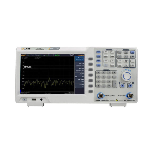
OWON OWON XSA815-TG Spectrum Analyzer (9 kHz – 1.5 GHz)
The OWON XSA815-TG (9 kHz-1.5 GHz) is a cost effective spectrum analyzer with tracking generator included and a frequency resolutions of 1 Hz. Features Frequency Range from 9 kHz to 1.500009 GHz 9-inch display 9 kHz to 1 MHz -95 dBm Displayed Average Noise Level, 1 MHz to 500 MHz 140 dBm (Typical), <-130 dBm Phase Noise -10 kHz <-80 dBc/Hz 100 kHz <-100 dBc/Hz 1 MHz <-115 dBc/Hz Resolution Bandwidth (-3 dB): 1 Hz to 1 MHz, in 1-3-5-10 sequence Tracking Generator Kit: 100 kHz to 1.500009 GHz Specifications Frequency Range 9 kHz to 500.009 MHz Frequency Resolution 1 Hz Frequency Span 9 kHz to 1.500009 GHz Span Range 0 Hz, 100 Hz to max frequency of instrument Span Uncertainty ±span / (sweep points-1) SSB Phase Noise (20°C to 30°C, fc=1 GHz) Carrier Offset 10 kHz <-80 dBc/Hz | 100 kHz <-100 dBc/Hz | 1 MHz <-115 dBc/Hz Resolution Bandwidth (-3 dB) 1 Hz to 1 MHz, in 1-3-5-10 sequence RBW Accuracy <5% typical Resolution Filter Shape Factor (60 dB: 3 dB) <5 typical Video Bandwidth (-3 dB) 10 Hz to 1 MHz, in 1-3-5-10 sequence Amplitude measurement range DANL to +10 dBm, 100 kHz to 10 MHz, Preamp Off DANL to +20 dBm, 10 MHz to 1.5 GHz, Preamp Off Reference Level -80 dBm to +30 dBm, 0.01dB by step Preamp 20 dB, nominal, 100 kHz to 1.5 GHz Input Attenuator 0 to 40 dB, 1 dB by step Display Average Noise Level Input attenuation = 0 dB, RBW = VBW = 100 Hz, sample detector, trace average ≥ 50, 20°C to 30°C, input impedance = 50 Ω) Preamp Off 9 kHz to 1 MHz -95 dBm (Typical), <-88 dBm Preamp Off 1 MHz to 500 MHz -140 dBm (Typical), <-130 dBm Preamp On 100 kHz to 1 MHz -135 dBm (Typical), <-128 dBm Preamp On 1 MHz to 500 MHz -160 dBm (Typical),<-150 dBm Tracking Generator (optional) Frequency Range 100 kHz to 1.500009 GHz Output power level range -40 dBm to 0 dBm Output level resolution 1 dB Output flatness Relative to 50 MHz | ±3 dB Tracking generator spurious Harmonic spurious -30 dBc (Tracking generator output power -10 dBm) Non-harmonic spurious -40 dBc (Tracking generator output power -10 dBm) Tracking generator to input terminal isolation -60 dB (Tracking generator output power 0 dBm) Tracking generator to input terminal isolation -60 dB (Tracking generator output power 0 dBm) Tracking generator to input terminal isolation -60 dB (Tracking generator output power 0 dBm) Dimensions 375 x 185 x 120 mm Weight 3.7 kg Included 1x XSA815-TG 1x 220 V AC power cord 1x USB Cable 1x Quickstart guide Downloads Quick Guide Specifications
€ 907,50
-

JOY-iT Passive Cooling for Raspberry Pi (Heatsink)
Aluminium Heatsink Set for Raspberry Pi with pre-applied tape for easy installation 1 piece: 14 x 15 x 5 mm 2 pieces: 8 x 8 x 5 mm
€ 3,95€ 1,58
Members identical
-

Elektor Digital PC Programming (E-book)
A Small Basic Approach There are many different PC programming languages available on the market. Some have beautiful names; some have easy to use development tools. Others have incredible power. They all have one thing in common: they assume that you have, or want to have, a knack for technology and difficult to read commands. In this book we take a practical approach to programming. We assume that you simply want to write a PC program, and write it quickly. Not in a professional environment, not in order to start a new career, but for plain and simple fun... or just to get a task done. Therefore we use Small Basic. You will have an application up and running in a matter of minutes. You will understand exactly how it works and be able to write text programs, graphical user interfaces, and advanced drivers. It is so simple; you don't even need to be an adult!
€ 29,95
Members € 23,96
-
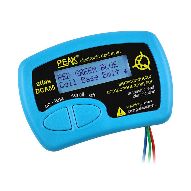
Peak Peak Atlas DCA55 Semiconductor Analyzer
The Peak Atlas DCA55 is great for automatically identifying the type of semiconductor on the test leads as well as the pinout and many other parameters. Supports transistors MOSFETs, JFETs (gate pin only can be identified), diodes, LEDs and lots more. Automatically identifies type of component, pinout and other important parameters. Now features transistor leakage measurement and Germanium/Silicon identification. Component Support Bipolar transistors (NPN/PNP inc Silicon/Germanium) Darlington transistors (NPN/PNP) Enhancement mode MOSFETs (N-Ch and P-Ch) Depletion mode MOSFETs (N-Ch and P-Ch) Junction FETs (N-Ch and P-Ch). Only gate lead identified Diodes and diode networks (2 and 3 lead types) LEDs and bi-colour LEDs (2 lead and 3 lead types) Low power sensitive Triacs and Thyristors (<5 mA trigger and hold) Measurements Part type identification Pinout identification BJT current gain (hFE) BJT base emitter voltage (Vbe) BJT collector leakage current MOSFET gate threshold voltage Diode forward voltage drop (Vf) Specifications Analyzer type Transistors, Diodes, LEDs, MOSFETs, JFETs Pinout detection Full pinout (only Gate on JFETs) Pinout configuration Connect any way round Transistor measurements Vbe, hFE, Iceo MOSFET measurements Vgs(on) Diode measurements Vf Probe type Universal grabber type Battery Single AAA cell (supplied). Life typically 1300 ops Test conditions Typically 5 mA, 5 V peak Display type Alphanumeric LCD (with backlight) Included Peak Atlas DCA55 Semiconductor Analyzer Comprehensive illustrated user guide Fitted universal hook probes AAA Alkaline battery Downloads Datasheet (EN) User Guide (EN) User Guide (IT)
€ 59,95
-
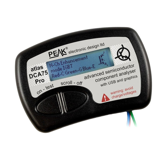
Peak Peak Atlas DCA75 Pro (Advanced Semiconductor Analyzer)
The DCA75 Pro is a great instrument that combines ease-of-use with amazing features. It can automatically identify a huge range of semiconductors, automatically identify pinouts and measure detailed parameters. Features Built-in graphics display (now backlit) to show detailed schematic of the component you're testing as well as pinout and measurement data USB connectivity to allow curve tracing, data storage/retrieval and device matching on your Windows PC (Windows 7 and higher) Single internal AAA alkaline cell for standalone operation Component Support Bipolar transistors (NPN/PNP inc Silicon/Germanium) Darlington transistors (NPN/PNP) Enhancement mode MOSFETs (N-Ch and P-Ch) Depletion mode MOSFETs (N-Ch and P-Ch) Junction FETs (N-Ch and P-Ch). Both symmetrical and asymmetrical types Enhancement IGBTs (N-Ch and P-Ch) Diodes and diode networks (2 and 3 lead types) Zener diodes (up to about 9 V) Voltage regulators (up to about 8 V) LEDs and bi-colour LEDs (2 lead and 3 lead types) Low power sensitive Triacs and Thyristors (<10 mA trigger and hold) Measurements BJT current gain (hFE) BJT base emitter voltage (Vbe) BJT collector leakage current MOSFET on and off gate threshold voltages MOSFET transconductance JFET pinch-off voltage JFET transconductance JFET IDSS (drain current for Vgs=0) IGBT on and off gate threshold voltages IGBT transconductance Voltage regulator output voltage Voltage regulator quiescent current consumption Voltage regulator drop-out voltage Zener voltage Diode forward voltage drop Specifications Analyzer type Semiconductor components Component detection Automatic Pinout detection Automatic, connect any way round Display type Graphic LCD (now backlit) Interface type USB for optional PC connection PC functions Curve tracing (Windows 7 and higher) Software Included on USB drive for Windows 7 and higher Battery Single AAA cell (supplied) Included Peak Atlas DCA75 Pro PC software on a USB Flash Drive for Windows 11, 10, 8, 7, XP Micro USB cable Fitted universal premium hook probes AAA Alkaline battery Downloads Datasheet (EN) User Guide (EN) User Guide (IT) Software Installation Guide (EN) Software and Firmware Package
€ 167,05
-
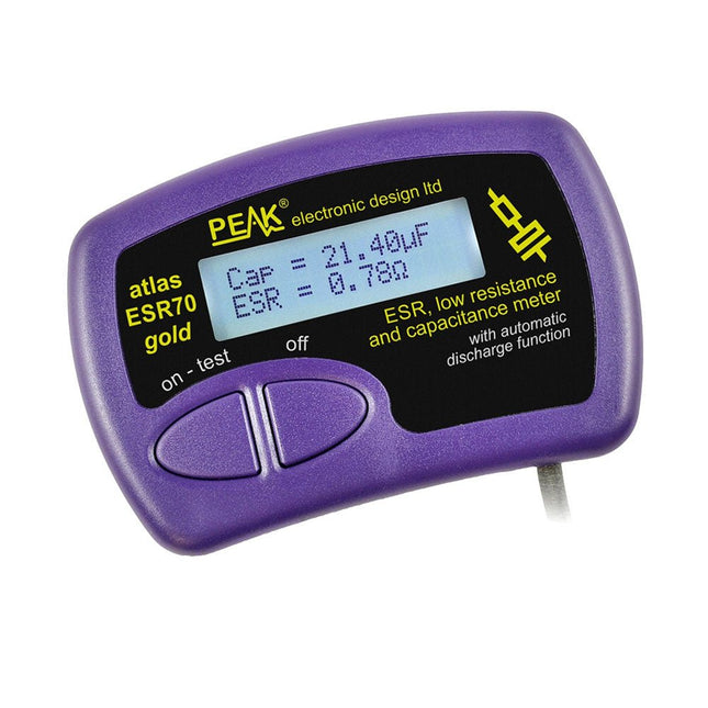
Peak Peak Atlas ESR70 gold (ESR and Capacitance Meter)
The Peak Atlas ESR70 gold is an enhanced version of the previous Peak Atlas ESR70 Plus. It does everything that the ESR70 Plus did but better. It now measures capacitance up to 10x faster, and over a wider range, thanks to new test algorithms. The capacitance measurement is also much less influenced by parallel resistances or leakage current thanks to our new Triple-Slope measurement system. Using the supplied gold plated probes (removable), the Atlas ESR70 gold can measure ESR down to a resolution of 0.01 ohms, up to 40 ohms. It can even measure ESR for capacitors that are in-circuit. Probes are removable, allowing 2 mm compatible probes to be fitted. Audible alerts are produced for various ESR levels allowing you to perform many tests in succession without having to look at the display. The ESR70 automatically takes capacitive reactance into account, so even low value capacitors (down to 0.3 uF) can have the ESR measured accurately. Features Uses a single AAA Alkaline cell (included) Alphanumeric LCD with backlight Automatic analysis-start when you apply the probes Automatic capacitor discharge using controlled discharge function ESR (and low DC resistance) measurement (even in-circuit) Capacitive reactance automatically taken into account to ensure accurate ESR Capacitance measurement (if testing out-of-circuit) Audible alerts for various ESR levels Extended ESR measurement range up to 40 Ohms Optional probe alternatives easily fitted New gold Features Improved LCD with better backlight 10x faster capacitance measurement for large capacitors Enhanced user options system New triple-slope measurement system to vastly reduce the influence of parallel resistance and/or leakage current on capacitance measurements Much wider capacitance measurement range now 0.3 uF to 90,000 uF (was 1uF to 22,000uF) Specifications Analyzer type ESR and Capacitance Component types Capacitors (>0.3 uF) ESR range 0.00 Ohms to 40.0 Ohms ESR resolution From 0.01 Ohms In-circuit use ESR only Capacitance range 0.3 uF to 90000 uF Battery type 1.5 V Alkaline AAA Cell (supplied). Life typically 1500 ops Display type Alphanumeric LCD (with backlight) Included Peak Atlas ESR70 gold Extra-long and extra-flexible test cables (450 mm of Silicone covered cable) 2 mm gold plated plugs and sockets with removeable gold plated crocodile clips Comprehensive illustrated user guide AAA Alkaline cell Downloads Datasheet (EN) User Guide (EN) User Guide (FR) User Guide (IT)
€ 99,00
-
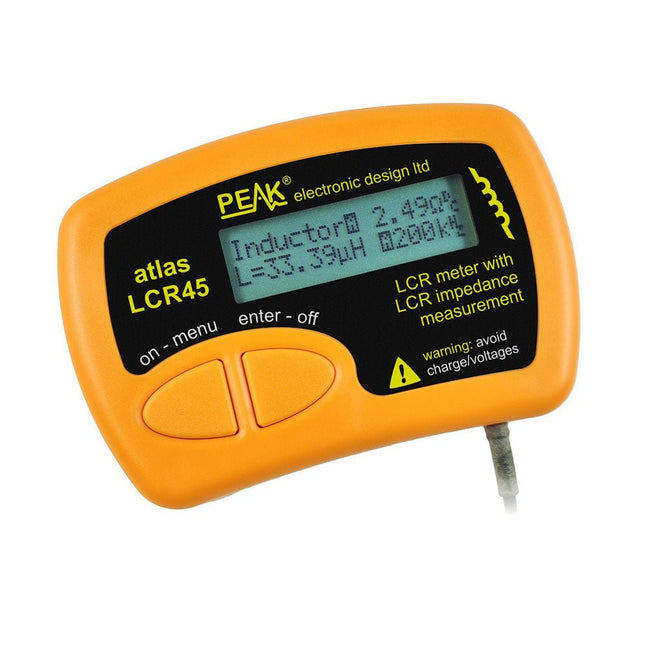
Peak Peak Atlas LCR45 LCR Meter
The Peak Atlas LCR45 does everything that the popular LCR40 does, but it has some significant enhancements. The LCR45 features a new high capacity micro and high resolution ADCs. LCR45 incorporates advanced maths, based on Complex Impedance analysis. This allows for enhanced component value measurement as well as a comprehensive and detailed impedance display. Features Supplied with gold plated removable hook probes Fluid measurements with hold function Automatic or manual component type Automatic or manual test frequency, DC, 1 kHz, 15 kHz or 200 kHz Enhanced measurement resolution: 0.2 µH, 0.2 pF and 0.2 Ohms Easy menu system for user settings Enhanced compensation for component parasitics and losses (such as core losses etc) Automatic or manual power-off Specifications Analyser type LCR and component impedance Component types Auto/Manual for L,C & R Measurement types Inductance, Capacitance and Resistance Other measurements Complex impedance/admittance More measurements Magnitude and Phase of impedance Inductance range 0uH to 2H Capacitance range 0 pF to 10000 uF Resistance range 0R to 2MR Test frequency Auto and manual: DC, 1 kHz, 15 kHz, 200 kHz Display type Alphanumeric LCD (not backlit) Measurement scheme Continuous (with optional hold) Battery GP23 (12 V/55 mAH type), ~700 ops Included LCR45 Passive Component Impedance Meter 2 mm plugs and sockets and removeable hook probes Comprehensive illustrated user guide 2 Batteries, one installed and one spare. GP23 Alkaline battery. (12 V/55 mAH) Downloads Datasheet (EN) User Guide (EN) User Guide (FR) User Guide (IT)
€ 117,98
-
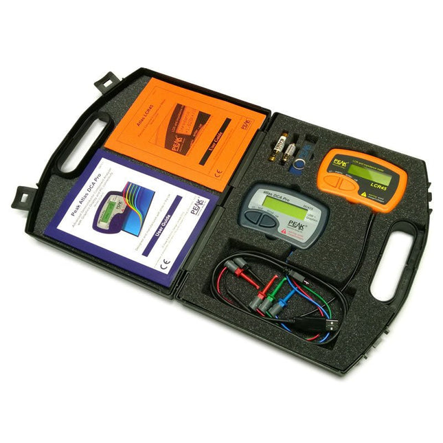
Peak Peak Atlas Pro Pack (LCR45 & DCA75)
This pack contains the LCR45 Passive Component Impedance Meter, great for advanced hobbyists and professionals. It also contains the very popular DCA Pro (model DCA75), fantastic for component identification, pinout identification, detailed characteristic measurement and curve tracing on a PC. Complete with USB cable and software on a USB flash drive. DCA75 Building on the continued success of Peak's existing component identification and analysis instruments, the DCA Pro brings an array of exciting new features for the hobbyist and professional alike. The DCA Pro is an advanced new design that features a graphics display, USB communications, PC Software and an enhanced component identification library. Automatic component type identification Automatic pinout identification (connect any way round) The DCA Pro supports all the components that the popular Peak Atlas DCA55 supports, but adds plenty more. Components supported include: Transistors (including Darlingtons), Silicon and Germanium types. Measures gain, Vbe and leakage MOSFETs, enhancement mode and depletion mode types. Measure on-threshold (at 5 mA) and approx transconductance (for span of 3-5 mA) JFETs, including normally off SiC types. Measures pinch-off voltage (at 1 uA) and approx transconductance (for span of 3-5 mA) IGBTs (insulated gate bipolar transistors). Measures on-threshold (at 5 mA) Diodes and Diode networks LEDs and bicolour LEDs (2 lead and 3 lead types) Zener Diodes with measurement of zener voltage up to 9 V at 5 mA Voltage regulators (measures regulation voltage, drop-out voltage, quiescent current) Triacs and Thyristors that require less than 10 mA of gate current and holding current Stand-alone or with a PC The instrument can be used stand-alone or connected to a PC. Either way, the DCA Pro will automatically identify the component type, identify the pinout and also measure a range of component parameters such as transistor gain, leakage, MOSFET and IGBT threshold voltages, pn characteristics and much more. Curve Tracing When connected to a PC using the supplied USB cable, a range of low current curve-tracing functions can be performed. Various graph types are available, with more to follow: Bipolar transistor output characteristics, IC vs VCE Bipolar transistor gain characteristics, HFE vs VCE Bipolar transistor gain characteristics, HFE vs IC MOSFET and IGBT output function, ID vs VDS MOSFET and IGBT transfer function, ID vs VGS JFET output function, ID vs VDS JFET transfer function, ID vs VGS Voltage regulator, VOUT vs VIN Voltage regulator, IQ vs VIN. PN junction I/V curves, forward and reverse options (for Zener diodes) Curve tracing is performed using test parameters in the range of +/-12 V or +/-12 mA. All curve-tracing data can be instantly pasted into Excel for further graphing and analysis. PC Software is included with the DCA Pro on a Peak USB memory stick. Software designed for Windows 7 and higher (all 32 or 64 bit). LCR45 A great handheld LCR analyzer that can measure the value of your passive component (inductor, capacitor or resistor) and also measure the detailed impedance in a number of modes. The LCR45 offers enhanced measurement resolution (better than 0.1 uH!) whilst also giving you continuous fluid measurements. Additionally, the test frequencies of DC, 1 kHz, 15 kHz and 200 kHz can be set to automatic or manual modes. Supplied with removable gold plated hook probes, battery and user guide. Compatible with standard 2 mm test connectors. Not designed for in-circuit use. Automatic or manual component type selection: Inductor, Capacitor or Resistor Automatic or manual test frequency selection: DC, 1 kHz, 15 kHz and 200 kHz Inductance from 0.1 uH to 10 H Capacitance from 0.1 pF to 10,000 uF Resistance from 0.1 Ohm to 2 MOhm Inductance measurement also shows DC winding resistance Display of "Component type and values", "Complex Impedance", "Magnitude/Phase" and "Admittance" Test frequency displayed for all measurements Typical accuracy of 1.5% for inductors and capacitors (see spec table for details) Typical accuracy of 1% for resistors Test lead complete with gold plated 2 mm plugs and sockets Supplied with removable gold plated hook probes Included LCR45 DCA75 Extra GP23 Battery Extra AAA cell Dual Carry Case
€ 270,00
-
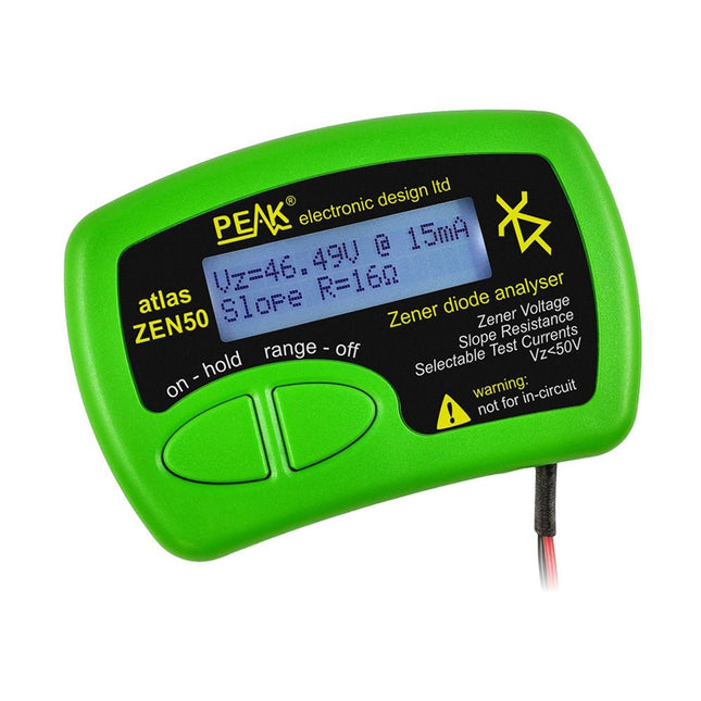
Peak Peak Atlas ZEN50 Zener Diode Analyzer
The Peak Atlas ZEN50 is ideal for testing Zener diodes (including avalanche diodes), transient suppressors, LEDs and LED strings. It generates constant current pulses (selectable from 2 mA, 5 mA, 10 mA and 15 mA) at voltages from 0 V to 50 V. So even high voltage Zeners or high voltage LED strings can be tested. Test currents are supplied in narrow pulses to ensure that the component under test remains at a constant temperature. The voltage of the part is displayed on the screen together with the test current and also a measure of the component's slope resistance (also known as dynamic impedance). Specifications Analyzer type Zeners, LEDs, TVS etc Test currents 2 mA, 5 mA, 10 mA, 15 mA Voltage range 0.00 to 50.00 V Slope resistance range 0 to 8000 Ohms Battery type Single AAA (supplied). Life typically 1400 ops Test method Triple pulse burst @ 10pps (typ) Test current duty cycle 3% Display type Alphanumeric LCD (with backlight) Included Peak Atlas ZEN50 Zener Diode Analyzer Fitted flexible test leads with gold plated crocs Comprehensive illustrated user guide AAA Alkaline battery Downloads Datasheet (EN) User Guide (EN) User Guide (FR) User Guide (DE) User Guide (IT)
€ 79,00


