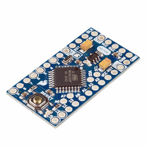
This affordable and increasingly powerful FPGA board is a fantastic starting point into the world of FPGAs and the heart of your next project. Finally, now that SparkFun builds this board, we added a Qwiic connector for easy I²C integration!
The Alchitry Au features a Xilinx Artix 7 XC7A35T-1C FPGA with over 33,000 logic cells and 256 MB of DDR3 RAM. The Au offers 102 3.3 V logic level IO pins, 20 of which can be switched to 1.8 V; Nine differential analogue inputs; Eight general-purpose LEDs; a 100 MHz on-board clock that can be manipulated internally by the FPGA; a USB-C connector to configure and power the board; and a USB to serial interface for data transfer. To make getting started even easier, all Alchitry boards have full Lucid support, a built-in library of useful components to use in your project, and a debugger!
Features
Artix 7 XC7A35T-1C - 33,280 logic cells
256 MB DDR3 RAM
102 IO pins (3.3 V logic level, 20 of them can be switched to 1.8 V for LVDS)
Nine differential analogue inputs (One dedicated, Eight mixed with digital IO)
USB-C to configure and power the board
Eight general-purpose LEDs
One button (typically used as a reset)
100 MHz on-board clock (can be multiplied internally by the FPGA)
Powered with 5 V through USB-C port, 0.1" holes, or headers
USB to serial interface for data transfer (up to 12 Mbaud)
Qwiic Connector
Dimensions: 65 x 45 mm
Downloads
Datasheet
Schematic
3D Model (IGES File)
Element Eagle Library
This exceptional GPS/GNSS antenna is designed for both GPS and GLONASS reception. The magnetic mount allows it to be easily mounted to a metal base such as a ground plate or car roof. The antenna is terminated with a 3m cable and standard SMA connector. Features Dimensions: 50x38x17mm Weight: 75g including 3m cable Frequency Range: 1575 - 1610MHz GPS Center Frequency: 1575.42MHz GLONASS Center Frequency: 1602MHz LNA Voltage: 3 to 5VDC LNA Gain: 28dB LNA Current: 10mA Termination Connector: SMA Impedance: 50Ω Right-hand polarization Cable Length: 3 meter
An assortment of coloured wires: you know it's a beautiful thing. Six different colours of stranded wire in a cardboard dispenser box. Sit this on your workbench, and stop worrying about having a piece of wire around!
Included
22 AWG
25 ft / Spool
6 Spools in Six Different Colors
Colours are Red, Blue, Yellow, Green, Black, and White
Dispenser Box
The Molex Flexible GNSS Antenna has a tiny footprint at 40.40mm x 15.40mm, while the adhesive pad is a bit bigger at 56.40mm x 20mm. Even better, the antenna is only 0.1mm thick (or about the thickness of a piece of paper). Remove the backing and stick this to any surface, or leave the backing on (be careful of the fragile U.FL connector). Features Cable length: 50mm Connector: U.FL Radiation Pattern: Omnidirectional Polarization: Linear Weigth: 0.466 g Mounting Style: Adhesive Protocol: BeiDou, Galileo, GLONASS, GPS Return Loss: < -8dB Peak Gain (Max): 1.1 dBi+ Efficiency: >74% Input Impedance 50 Ohms
This is a 100mm long 4-conductor cable with 1mm JST termination. It’s designed to connect Qwiic enabled components but can be used for other applications as well. Each Qwiic Cable's wires have been colour-coded to Red, Black, Blue, and Yellow.
The Arduino Pro Mini is a microcontroller board based on the ATmega328P. It has 14 digital input/output pins (of which 6 can be used as PWM outputs), 6 analog inputs, an on-board resonator, a reset button, and holes for mounting pin headers. A six pin header can be connected to an FTDI cable or Sparkfun breakout board to provide USB power and communication to the board. The Arduino Pro Mini is intended for semi-permanent installation in objects or exhibitions. The board comes without pre-mounted headers, allowing the use of various types of connectors or direct soldering of wires. The pin layout is compatible with the Arduino Mini. The Arduino Pro Mini was designed and is manufactured by SparkFun Electronics. Specifications Microcontroller ATmega328P Board Power Supply 5-12 V Circuit Operating Voltage 5 V Digital I/O Pins 14 PWM Pins 6 UART 1 SPI 1 I²C 1 Analog Input Pins 6 External Interrupts 2 DC Current per I/O Pin 40 mA Flash Memory 32 KB of which 2 KB used by bootloader SRAM 2 KB EEPROM 1 KB Clock Speed 16 MHz Dimensions 18 x 33.3 mm (0.7 x 1.3') Downloads Eagle files Schematics
The flexibility of the Artemis module starts with SparkFun's Arduino core. You can program and use the Artemis module just like you would an Uno or any other Arduino. The time to first blink is just 5 minutes away! We built the core from the ground up, making it fast and as lightweight as possible.
Next is the module itself. Measuring 10 x 15 mm, the Artemis module has all the support circuitry you need to use the fantastic Ambiq Apollo3 processor in your next project. We're proud to say the SparkFun Artemis module is the first open-source hardware module with the design files freely and easily available. We've carefully designed the module so that implementing Artemis into your design can be done with low-cost 2-layer PCBs and 8mil trace/space.
Made in the USA at SparkFun's Boulder production line, the Artemis module is designed for consumer-grade products. This truly differentiates the Artemis from its Arduino brethren. Ready to scale your product? The Artemis will grow with you beyond the Uno footprint and Arduino IDE. Additionally, the Artemis has an advanced HAL (hardware abstraction layer), allowing users to push the modern Cortex-M4F architecture to its limit.
The SparkFun Artemis Module is fully FCC/IC/CE certified and is available in full tape and reel quantities. With 1M flash and 384k RAM, you'll have plenty of room for your code. The Artemis module runs at 48MHz with a 96MHz turbo mode available and with Bluetooth to boot!
The servo control is based on the SparkFun servo pHAT, and thanks to its I2C capabilities, this PWM add-on saves the Raspberry Pi's GPIO pins, allowing you to use them for other purposes. We have also provided a Qwiic connector for easy interfacing with the I²C bus using the Qwiic system. Whether you use the Auto pHAT with a Raspberry Pi, NVIDIA, Jetson Nano, Google Coral, or other SBC, it makes for a unique robotics addition and board with a 2x20 GPIO.
The DC motor control comes from the same 4245 PSOC and 2-channel motor ports system used on the SparkFun Qwiic Motor Driver. This provides 1.2A steady-state drive per channel (1.5A peak) and 127 levels of DC drive strength. The SparkFun Auto pHAT also supports up to two motor encoders thanks to the onboard ATTINY84A to provide more precise movement to your creation!
Additionally, the Auto pHAT has an on-board ICM-20948 9DOF IMU for all your motion-sensing needs. This enables your robot to access the 3-Axis Gyroscope with four selectable ranges, 3-Axis Accelerometer, again with four selectable ranges, and 3-axis magnetometer with an FSR of ±4900µT.
Power to the SparkFun Auto pHAT can be supplied through a USB-C connector or external power. This will power either the motors only or power the motors and the Raspberry Pi that is connected to the HAT. We've even added power protection circuits to the design to avoid damage to power sources.
Features
4245 PSOC and 2-channel motor ports programmable using Qwiic library
Onboard ATTINY84A supports up to two DC motor encoders
5V pass-through from RPi
Onboard ICM-20948 9DOF IMU for motion sensing accessible via Qwiic library
PWM control for up to four servos
Qwiic connector for expansion to full SparkFun Qwiic ecosystem
Designed for stacking, full header support & can use additional pHATs on top of it
Uninhibited access to the RPi camera connector & display connector.
USB-C for powering 5V rail (Motors/Servos/back powering Pi)
External power inputs broken out to PTH headers
The SparkFun DataLogger IoT (9DoF) is a data logger that comes preprogrammed to automatically log IMU, GPS, and various pressure, humidity, and distance sensors. All without writing a single line of code! The DataLogger automatically detects, configures, and logs Qwiic sensors. It was specifically designed for users who just need to capture a lot of data to a CSV or JSON file and get back to their larger project. Save the data to a microSD card or send it wirelessly to your preferred Internet of Things (IoT) service!
Included on every DataLogger IoT is an IMU for built-in logging of a triple-axis accelerometer, gyro, and magnetometer. Whereas the original 9DOF Razor used the old MPU-9250, the DataLogger IoT uses the ISM330DHCX from STMicroelectronics and MMC5983MA from MEMSIC. Simply power up the DataLogger IoT, configure the board to record readings from supported devices, and begin logging! Data can be time-stamped when the time is synced to NTP, GNSS, or RTC.
The DataLogger IoT is highly configurable over an easy-to-use serial interface. Simply plug in a USB-C cable and open a serial terminal at 115200 baud. The logging output is automatically streamed to both the terminal and the microSD card. Pressing any key in the terminal window will open the configuration menu.
The DataLogger IoT (9DoF) automatically scans, detects, configures, and logs various Qwiic sensors plugged into the board (no soldering, no programming!).
Specifications
ESP32-WROOM-32E Module
Integrated 802.11b/g/n WiFi 2.4 GHz transceiver
Configurable via CH340C
Operating voltage range
3.3 V to 6.0 V (via VIN)
5 V with USB (via 5 V or USB type C)
3.6 V to 4.2 V with LiPo battery (via BATT or 2-pin JST)
Built-in MCP73831 single cell LiPo charger
Minimum 500 mA charge rate
3.3 V (via 3V3)
MAX17048 LiPo Fuel Gauge
Ports
1x USB-C
1x JST style connector for LiPo battery
2x Qwiic enabled I²C
1x microSD socket
Support for 4-bit SDIO and microSD cards formatted to FAT32
9-axis IMU
Accelerometer & Gyro (ISM330DHCX)
Magnetometer (MMC5983MA)
LEDs
Charge (CHG)
Status (STAT)
WS2812-2020 Addressable RGB
Jumpers
IMU interrupt
Magnetometer interrupt
RGB LED
Status LED
Charge LED
I²C pull-up resistors
USB Shield
Buttons
Reset
Boot
Dimensions: 1.66 x 2.0' (4.2 x 5.1 cm)
Weight: 10.7 g
Downloads
Schematic
Eagle Files
Board Dimensions
Hookup Guide
CH340 Drivers
Firmware
GitHub Hardware Repo
The VL53L1X from STMicroelectronics uses a VCSEL (Vertical Cavity Surface Emitting Laser) to emit an Infrared laser to time the reflection to the target. That means that you will be able to measure the distance to an object from 40mm to 4m away with millimeter resolution! To make it even easier to get your readings, all communication is enacted exclusively via I²C, utilizing our handy Qwiic system, so no soldering is required to connect it to the rest of your system. However, we still have broken out 0.1”-spaced pins in case you prefer to use a breadboard. Each VL53L1X sensor features a precision to be 1mm with an accuracy around +/-5mm, and a minimum read distance of this sensor is 4cm. The field of view for this little breakout is fairly narrow at 15°-27° with a read rate of up to 50Hz. Make sure to power this board appropriately since it will need 2.6V-3.5V to operate. Lastly, please be sure to remove the protective sticker on the VL53L1X before use otherwise it will, most assuredly, throw off your readings. Features Operating Voltage: 2.6V-3.5V Power Consumption: 20 mW @10Hz Measurement Range: ~40mm to 4,000mm Resolution: +/-1mm Light Source: Class 1 940nm VCSEL 7-bit unshifted I²C Address: 0x29 Field of View: 15° - 27° Max Read Rate: 50Hz
Reinforcing its commitment to widening the accessibility to and innovation in the area of deep learning, NVIDIA has created a free, self-paced, online Deep Learning Institute (DLI) course, “Getting Started on AI with Jetson Nano.” The course's goal is to build foundational skills to enable anyone to get creative with the Jetson Developer Kit. Please be aware that this kit is for those who already own a Jetson Nano Developer Kit and want to join the DLI Course. A Jetson Nano is not included in this kit.
Included in this kit is everything you will need to get started in the “Getting Started on AI with Jetson Nano” (except for a Jetson Nano, of course), and you will learn how to
Set up your Jetson Nano and camera
Collect image data for classification models
Annotate image data for regression models
Train a neural network on your data to create your own models
Run inference on the Jetson Nano with the models you create
The NVIDIA Deep Learning Institute offers hands-on training in AI and accelerated computing to solve real-world problems. Developers, data scientists, researchers, and students can get practical experience powered by GPUs in the cloud and earn a competency certificate to support professional growth. They offer self-paced, online training for individuals, instructor-led workshops for teams, and downloadable course materials for university educators.
Included
32 GB microSD Card
Logitech C270 Webcam
Power Supply 5 V, 4 A
USB Cable - microB (Reversible)
2-Pin Jumper
Please note: Jetson Nano Developer Kit not included.
To make it even easier to use this breakout, all communication is enacted exclusively via I²C, utilizing our handy Qwiic system. However, we still have broken out 0.1' spaced pins in case you prefer to use a breadboard.
The CCS811 is an exceedingly popular sensor, providing readings for equivalent CO2 (or eCO2) in the parts per million (PPM) and total volatile organic compounds in the parts per billion (PPB). The CCS811 also has a feature that allows it to fine-tune its readings if it has access to the current humidity and temperature.
Luckily, the BME280 provides humidity, temperature and barometric pressure! This allows the sensors to work together to give us more accurate readings than they’d be able to provide on their own. We also made it easy to interface with them via I²C.
Features
Qwiic-Connector Enabled
Operation Voltage: 3.3 V
Total Volatile Organic Compound (TVOC) sensing from 0 to 1,187 parts per billion
eCO2 sensing from 400 to 8,192 parts per million
Temp Range: −40°C to +85°C
Humidity Range: 0-100% RH, = -3% from 20-80%
Pressure Range: 30,000Pa to 110,000Pa, relative accuracy of 12Pa, absolute accuracy of 100Pa
Altitude Range: 0 to 30,000 feet (9.2 km), relative accuracy of 3.3 feet (1 m) at sea level, 6.6 (2 m) at 30,000 feet
Additionally, this u-blox receiver supports I²C (u-blox calls this Display Data Channel), making it perfect for the Qwiic compatibility, so we don't have to use up our precious UART ports. Utilizing our handy Qwiic system, no soldering is required to connect it to the rest of your system. However, we still have broken out 0.1'-spaced pins if you prefer to use a breadboard.
The NEO-M9N module detects jamming and spoofing events and can reports them to the host so that the system can react to such events. A SAW (Surface Acoustic Wave) filter combined with an LNA (Low Noise Amplifier) in the RF path is integrated into the NEO-M9N module, allowing normal operation even under strong RF interferences.
U-blox based GPS products are configurable using the popular but dense, windows program called u-centre. Plenty of different functions can be configured on the NEO-M9N: baud rates, update rates, geofencing, spoofing detection, external interrupts, SBAS/D-GPS, etc. All of this can be done within the SparkFun Arduino Library!
The SparkFun NEO-M9N GPS Breakout is also equipped with an on-board rechargeable battery that provides power to the RTC on the NEO-M9N. This reduces the time-to-first fix from a cold start (~24s) to a hot start (~2s). The battery will maintain RTC and GNSS orbit data without being connected to power for plenty of time.
Features
Integrated U.FL connector for use with an antenna of your choice
92-Channel GNSS Receiver
1.5 m Horizontal Accuracy
25 Hz Max Update Rate (4 concurrent GNSS)
Time-To-First-Fix:
Cold: 24 s
Hot: 2 s
Max Altitude: 80,000 m
Max G: ≤ 4
Max Velocity: 500 m/s
Velocity Accuracy: 0.05 m/s
Heading Accuracy: 0.3 degrees
Time Pulse Accuracy: 30 ns
3.3 V VCC and I/O
Current Consumption: ~31 mA Tracking GPS+GLONASS
Software Configurable
Geofencing
Odometer
Spoofing Detection
External Interrupt
Pin Control
Low Power Mode
Many others!
Supports NMEA, UBX, and RTCM protocols over UART or I²C interfaces
Downloads
Schematic
Eagle Files
Board Dimensions
Hookup Guide
Building a GPS System
Datasheet (NEO-M9N)
Product Summary
Integration Manual
u-blox Protocol Specification
NEO-M9M Documents & Resources
u-center Software
SparkFun u-blox GNSS Arduino Library
GitHub Hardware Repo
The NEO-M8U module is a 72-channel u-blox M8 engine GNSS receiver, meaning it can receive signals from the GPS, GLONASS, Galileo, and BeiDou constellations with ~2.5-meter accuracy. The module supports the concurrent reception of three GNSS systems. The combination of GNSS and integrated 3D sensor measurements on the NEO-M8U provide accurate, real-time positioning rates of up to 30Hz.
Compared to other GPS modules, this breakout maximizes position accuracy in dense cities or covered areas. Even under poor signal conditions, continuous positioning is provided in urban environments and is also available during complete signal loss (e.g. short tunnels and parking garages). With UDR, position begins as soon as power is applied to the board, even before the first GNSS fix is available! Lock time is further reduced with an on-board rechargeable battery; you'll have backup power enabling the GPS to get a hot lock within seconds!
Additionally, this u-blox receiver supports I²C (u-blox calls this Display Data Channel), making it perfect for the Qwiic compatibility, so we don't have to use up our precious UART ports. Utilizing our handy Qwiic system, no soldering is required to connect it to the rest of your system. However, we still have broken out 0.1'-spaced pins if you prefer to use a breadboard.
U-blox based GPS products are configurable using the popular but dense, windows program called u-centre. Plenty of different functions can be configured on the NEO-M8U: baud rates, update rates, geofencing, spoofing detection, external interrupts, SBAS/D-GPS, etc. All of this can be done within the SparkFun Arduino Library!
The SparkFun NEO-M8U GPS Breakout is also equipped with an on-board rechargeable battery that provides power to the RTC on the NEO-M8U. This reduces the time-to-first fix from a cold start (~26s) to a hot start (~1.5s). The battery will maintain RTC and GNSS orbit data without being connected to power for plenty of time.
Features
Integrated U.FL connector for use with an antenna of your choice
72-Channel GNSS Receiver
2.5 m Horizontal Accuracy
30 Hz Max Update Rate
Time-To-First-Fix:
Cold: 26 s
Hot: 1.5 s
Max Altitude: 50,000 m
Max G: ≤4
Max Velocity: 500 m/s
Velocity Accuracy: 0.5m/s
Heading Accuracy: 1 degree
Built-In Accelerometer and Gyroscope
Time Pulse Accuracy: 30 ns
3.3 V VCC and I/O
Current Consumption: ~29 mA Continuous Tracking, Default Concurrent Mode
Software Configurable
Geofencing
Odometer
Spoofing Detection
External Interrupt
Pin Control
Low Power Mode
Many others!
Supports NMEA, UBX, and RTCM protocols over UART or I²C interfaces
The ZED-F9R module is a 184-channel u-blox F9 engine GNSS receiver, meaning it can receive signals from the GPS, GLONASS, Galileo, and BeiDou constellations with ~0.2-meter accuracy! That's right; such accuracy can be achieved with an RTK navigation solution when used with a correction source. Note that the ZED-F9R can only operate as a rover, so you will need to connect to a base station. The module supports the concurrent reception of four GNSS systems. The combination of GNSS and integrated 3D sensor measurements on the ZED-F9R provide accurate, real-time positioning rates of up to 30Hz. Compared to other GPS modules, this pHAT maximizes position accuracy in dense cities or covered areas. Even under poor signal conditions, continuous positioning is provided in urban environments and is also available during complete signal loss (e.g. short tunnels and parking garages). The ZED-F9R is the ultimate solution for autonomous robotic applications that require accurate positioning under challenging conditions. This u-blox receiver supports a few serial protocols. By default, we chose to use the Raspberry Pi's serial UART to communicate with the module. With pre-soldered headers, no soldering is required to stack the pHAT on a Raspberry Pi, NVIDIA Jetson Nano, Google Coral, or any single-board computer with the 2x20 form factor. We have also broken out a few 0.1'-spaced pins from the u-blox receiver. A Qwiic connector is also added in case you need to connect a Qwiic enabled device. U-blox based GPS products are configurable using the popular but dense, windows program called u-centre. Plenty of different functions can be configured on the ZED-F9R: baud rates, update rates, geofencing, spoofing detection, external interrupts, SBAS/D-GPS, etc. The SparkFun ZED-F9R GPS pHAT is also equipped with an on-board rechargeable battery that provides power to the RTC on the ZED-F9R. This reduces the time-to-first fix from a cold start (~24s) to a hot start (~2s). The battery will maintain RTC and GNSS orbit data without being connected to power for plenty of time. Features 1 x Qwiic Connector Integrated U.FL connector for use with an antenna of your choice Concurrent reception of GPS, GLONASS, Galileo and BeiDou 184-Channel GNSS Receiver Receives both L1C/A and L2C bands Horizontal Position Accuracy: 0.20 m with RTK Max Navigation Rate: Up to 30Hz Time to First Fix Cold: 24 s Hot: 2 s Operational Limits Max G: ≤4 G Max Altitude: 50 km Max Velocity: 500 m/s Velocity Accuracy: 0.5 m/s Heading Accuracy: 0.2 degrees Built-In Accelerometer and Gyroscope Time Pulse Accuracy: 30ns Voltage: 5 V or 3.3 V, but all logic is 3.3 V Current: ~85mA to ~130mA (varies with constellations and tracking state) Software Configurable Geofencing Odometer Spoofing Detection External Interrupt Pin Control Low Power Mode Supports NMEA, UBX, and RTCM protocols over UART
Based on the SparkFun GPS-RTK2 designs, the SparkFun GPS-RTK-SMA raises the bar for high-precision GPS and is the latest in a line of powerful RTK boards featuring the ZED-F9P module from u-blox. The ZED-F9P is a top-of-the-line module for high accuracy GNSS and GPS location solutions, including RTK capable of 10mm, three-dimensional accuracy. With this board, you will be able to know where your (or any object's) X, Y, and Z location is within roughly the width of your fingernail! The ZED-F9P is unique in that it is capable of both rover and base station operations. Utilizing our handy Qwiic system, no soldering is required to connect it to the rest of your system. However, we still have broken out 0.1"-spaced pins if you prefer to use a breadboard.
We've included a rechargeable backup battery to keep the latest module configuration and satellite data available for up to two weeks. This battery helps 'warm start' the module decreasing the time-to-first-fix dramatically. This module features a survey-in mode allowing the module to become a base station and produce RTCM 3.x correction data. Based on your feedback, we switched out the u.FL connector and included an SMA connector in this version of the board.
The number of configuration options of the ZED-F9P is incredible! Geofencing, variable I²C address, variable update rates, even the high precision RTK solution can be increased to 20Hz. The GPS-RTK2 even has five communications ports which are all active simultaneously: USB-C (which enumerates as a COM port), UART1 (with 3.3V TTL), UART2 for RTCM reception (with 3.3V TTL), I²C (via the two Qwiic connectors or broken out pins), and SPI.
SparkFun has also written an extensive Arduino library for u-blox modules to easily read and control the GPS-RTK-SMA over our Qwiic Connect System. Leave NMEA behind! Start using a much lighter weight binary interface and give your microcontroller (and its one serial port) a break. The SparkFun Arduino library shows how to read latitude, longitude, even heading and speed over I²C without the need for constant serial polling.
Features
Concurrent reception of GPS, GLONASS, Galileo and BeiDou
Receives both L1C/A and L2C bands
Voltage: 5 V or 3.3 V, but all logic is 3.3 V
Current: 68 mA - 130 mA (varies with constellations and tracking state)
Time to First Fix: 25 s (cold), 2 s (hot)
Max Navigation Rate:
PVT (basic location over UBX binary protocol) - 25 Hz
RTK - 20 Hz
Raw - 25 Hz
Horizontal Position Accuracy:
2.5 m without RTK
0.010 m with RTK
Max Altitude: 50 km
Max Velocity: 500 m/s
Weight: 6.8 g
Dimensions: 43.5 mm x 43.2 mm
2 x Qwiic Connectors
The SparkFun GPS-RTK2 raises the bar for high-precision GPS and is the latest in a line of powerful RTK boards featuring the ZED-F9P module from u-blox. The ZED-F9P is a top-of-the-line module for high accuracy GNSS and GPS location solutions, including RTK capable of 10 mm, three-dimensional accuracy. With this board, you will be able to know where your (or any object's) X, Y, and Z location is within roughly the width of your fingernail! The ZED-F9P is unique in that it is capable of both rover and base station operations. Utilizing our handy Qwiic system, no soldering is required to connect it to the rest of your system. However, we still have broken out 0.1"-spaced pins if you prefer to use a breadboard.
We've even included a rechargeable backup battery to keep the latest module configuration and satellite data available for up to two weeks. This battery helps 'warm-start' the module decreasing the time-to-first-fix dramatically. This module features a survey-in mode allowing the module to become a base station and produce RTCM 3.x correction data.
The number of configuration options of the ZED-F9P is incredible! Geofencing, variable I²C address, variable update rates, even the high precision RTK solution can be increased to 20 Hz. The GPS-RTK2 even has five communications ports which are all active simultaneously: USB-C (which enumerates as a COM port), UART1 (with 3.3 V TTL), UART2 for RTCM reception (with 3.3V TTL), I²C (via the two Qwiic connectors or broken out pins), and SPI.
Sparkfun has also written an extensive Arduino library for u-blox modules to easily read and control the GPS-RTK2 over the Qwiic Connect System. Leave NMEA behind! Start using a much lighter weight binary interface and give your microcontroller (and its one serial port) a break. The SparkFun Arduino library shows how to read latitude, longitude, even heading and speed over I²C without the need for constant serial polling.
Features
Concurrent reception of GPS, GLONASS, Galileo and BeiDou
Receives both L1C/A and L2C bands
Voltage: 5 V or 3.3 V, but all logic is 3.3 V
Current: 68 mA - 130 mA (varies with constellations and tracking state)
Time to First Fix: 25 s (cold), 2 s (hot)
Max Navigation Rate:
PVT (basic location over UBX binary protocol) - 25 Hz
RTK - 20 Hz
Raw - 25 Hz
Horizontal Position Accuracy:
2.5 m without RTK
0.010 m with RTK
Max Altitude: 50k m
Max Velocity: 500 m/s
2x Qwiic Connectors
Dimensions: 43.5 x 43.2 mm
Weight: 6.8 g
The full-color, spiral-bound SIK guidebook (included) contains step-by-step instructions with circuit diagrams and hookup tables for building each project and circuit with the included parts. Full example code is provided, new concepts and components are explained at the point of use, and troubleshooting tips offer assistance if something goes wrong.
The kit does not require any soldering and is recommended for beginners ages 10 and up looking for an Arduino starter kit. For SIK version 4.1, Sparkfun took an entirely different approach to teaching embedded electronics. In previous versions of the SIK, each circuit focused on introducing a new piece of technology. With SIK v4.1, components are introduced in the context of the circuit you are building. Each circuit builds upon the last, leading up to a project that incorporates all of the components and concepts introduced throughout the guide. With new parts and a completely new strategy, even if you've used the SIK before, you're in for a brand-new experience!
The SIK V4.1 includes the Redboard Qwiic, which allows you to expand into the SparkFun Qwiic ecosystem after becoming proficient with the SIK circuits. The SparkFun Qwiic Connect System is an ecosystem of I²C sensors, actuators, shields and cables that make prototyping faster and less prone to error. All Qwiic-enabled boards use a common 1mm pitch, 4-pin JST connector. This reduces the amount of required PCB space, and polarized connections mean you can’t hook it up wrong. With the addition of the SparkFun RedBoard Qwiic, you will need to download a new driver install that is different from the original SparkFun RedBoard.
Included
SparkFun RedBoard Qwiic
Arduino and Breadboard Holder
SparkFun Inventor's Kit Guidebook
White Solderless Breadboard
Carrying Case
SparkFun Mini Screwdriver
16 x 2 White-on-Black LCD (with headers)
SparkFun Motor Driver (with Headers)
Pair of Rubber Wheels
Pair of Hobby Gearmotors
Small Servo
Ultrasonic Distance Sensor
TMP36 Temp Sensor
6' USB Micro-B Cable
Jumper Wires
Photocell
Tricolour LED
Red, Blue, Yellow and Green LEDs
Red, Blue, Yellow and Green Tactile Buttons
10K Trimpot
Mini Power Switch
Piezo Speaker
AA Battery Holder
330 and 10K Resistors
Binder Clip
Dual-Lock Fastener
The SparkFun JetBot AI Kit V3.0 is a great launchpad for creating entirely new AI projects for makers, students, and enthusiasts interested in learning AI and building fun applications. It’s straightforward to set up and use and is compatible with many popular accessories.
Several interactive tutorials show you how to harness AI's power to teach the SparkFun JetBot to follow objects, avoid collisions, and more. The Jetson Nano Developer Kit (not included in this kit) offers useful tools like the Jetson GPIO Python library and is compatible with standard sensors and peripherals; including some new python compatibility with the SparkFun Qwiic ecosystem.
Additionally, the included image is delivered with the advanced functionality of JetBot ROS (Robot Operating System) and AWS RoboMaker Ready with AWS IoT Greengrass already installed. SparkFun’s JetBot AI Kit is the only kit currently on the market ready to move beyond the standard JetBot examples and into the world of connected and intelligent robotics.
This kit includes everything you need to get started with JetBot minus a Phillips head screwdriver and an Ubuntu desktop GUI. If you need these, check out the includes tabs for some suggestions from our catalogue. Please be aware that the ability to run multiple neural networks in parallel may only be possible with a full 5V-4A power supply.
Features
SparkFun Qwiic ecosystem for I²C communication
The ecosystem can be expanded using 4x Qwiic connectors on GPIO header
Example Code for Basic Motion, Teleoperation, Collision avoidance, & Object Following
Compact form factor to optimize existing neural net from NVIDIA
136° FOV camera for machine vision
Pre-flashed MicroSD card
Chassis assembly offers expandable architecture
No soldering required
Included
64 GB MicroSD card - pre-flashed SparkFun JetBot image:
Nvidia Jetbot base image with the following installed: SparkFun Qwiic python library package
Driver for Edimax WiFi adapter
Greengrass
Jetbot ROS
Leopard Imaging 136FOV wide-angle camera & ribbon cable
EDIMAX WiFi Adapter
SparkFun Qwiic Motor Driver
SparkFun Micro OLED Breakout (Qwiic)
All hardware & prototyping electronics needed to complete your fully functional robot!
Required
NVIDIA Jetson Nano Developer Kit
Downloads
Assembly Guide
This version of the Micro OLED Breakout is exactly the size of its non-Qwiic sibling, featuring a screen that is 64 pixels wide and 48 pixels tall and measuring 0.66' across. But it has also been equipped with two Qwiic connectors, making it ideal for I²C operations. We've also added two mounting holes and a convenient Qwiic cable holder incorporated into a detachable tab on the board that can be easily removed thanks to a v-scored edge. We've even made sure to include an I²C pull-up jumper and ADDR jumper on the back of the board, so if you have your own I²C pull-ups or need to change the I2C address of the board! Features Qwiic-Connector Enabled Operating Voltage: 3.3V Operating Current: 10mA (20mA max) Screen Size: 64x48 pixels (0.66' Across) Monochrome Blue-on-Black I²C Interface
With a Cortex-M4F with BLE 5.0 running up to 96MHz and with as low power as 6uA per MHz (less than 5mW), the M.2 MicroMod connector allows you to plug in a MicroMod Carrier Board with any number of peripherals. Let's have a look at what this processor board has to offer! If you need Machine Learning capabilities, Bluetooth, I²C functionality to connect to all our amazing Qwiic boards, and more the Artemis Processor is the perfect choice for your MicroMod Carrier Board. At the heart of SparkFun's Artemis Module is Ambiq Micro's Apollo3 processor, whose ultra-efficient ARM Cortex-M4F processor is spec’d to run TensorFlow Lite using only 6uA/MHz. We've routed two I²C buses, eight GPIO, dedicated digital, analogue, and PWM pins, multiple SPI as well as QuadSPI, and Bluetooth to boot. You really can't go wrong with this processor. Grab one today, pick up a compatible carrier board, and get hacking! Features 1 M Flash / 384 k RAM 48 MHz / 96 MHz turbo available 6uA/MHz (operates less than 5mW at full operation) 48 GPIO - all interrupt capable 31 PWM channels Built-in BLE radio and antenna 10 ADC channels with 14-bit precision with up to 2.67 million samples per second effective continuous, multi-slot sampling rate 2 channel differential ADC 2 UARTs 6 I²C buses 6 SPI buses 2/4/8-bit SPI bus PDM interface I²S Interface Secure 'Smart Card' interface FCC/IC/CE Certified (ID Number 2ASW8-ART3MIS)
1x USB dedicated for programming and debugging 1x UART with flow control 2 x I²C 1 x SPI 1 x Quad-SPI 8 x Fast GPIO 2 x Digital Pins 2 x Analog Pins 2 x PWM 1 x Differential ADC pair Status LED VIN Level ADC
A modern USB-C connector makes programming easy. In addition to the pins broken out, two separate Qwiic-enabled I²C ports allow you to easily daisy chain Qwiic-enabled devices. We've exposed the SWD pins for more advanced users who prefer to use professional tools' power and speed. A USB-A connector is provided for Processor Boards that have USB Host support. A backup battery is provided for processor boards with RTC. If you need a 'lot' of GPIO with a simple-to-program, ready for the market module, the ATP is the fix you need. We've even added a convenient jumper to measure the current consumption for low power testing. Features M.2 Connector Operating Voltage Range ~3.3 V to 6.0 V (via VIN to AP7361C 3.3V Voltage Regulator) 3.3 V (via 3V3) Ports 1x USB type C 1x USB type A Host 2x Qwiic Enabled I²C 1x CAN 1x I²S 2x SPI 2x UARTs 2x Dedicated Analog Pins 2x Dedicated PWM Pins 2x Dedicated Digital Pins 12x General Purpose Input Output Pins 1x SWD 2x5 header 1 mAh battery backup for RTC Buttons Reset Boot LEDs Power 3.3 V Phillips #0 M2.5x3mm screw included
The Data Logging Carrier Board breaks out connections for I²C via a Qwiic connector or standard 0.1'-spaced PTH pins along with SPI and serial UART connections for logging data from peripheral devices using those communication protocols.
The Data Logging Carrier Board allows you to control power to both the Qwiic connector on the board and a dedicated 3.3 V power rail for non-Qwiic peripherals so you can pick and choose when to power the peripherals you are monitoring the data from. It also features a charging circuit for single-cell Lithium-ion batteries along with a separate RTC battery-backup circuit to maintain power to a real-time clock circuit on your Processor Board.
Features
M.2 MicroMod Connector
microSD socket
USB-C Connector
3.3 V 1 A Voltage Regulator
Qwiic Connector
Boot/Reset Buttons
RTC Backup Battery & Charge Circuit
Independent 3.3 V regulators for Qwiic bus and peripheral add-ons
Controlled by digital pins on Processor Board to enable low power sleep modes
Phillips #0 M2.5 x 3 mm screw included
The MicroMod DIY Carrier Kit includes five M.2 connectors (4.2mm height), screws, and standoffs so that you can get all the special parts you may need to make your own carrier board. MicroMod uses the standard M.2 connector. This is the same connector found on modern motherboards and laptops. There are various locations for the plastic ‘key’ on the M.2 connector to prevent a user from inserting an incompatible device. The MicroMod standard uses the ‘E’ key and further modifies the M.2 standard by moving the mounting screw 4mm to the side. The ‘E’ key is fairly common so a user could insert an M.2 compatible Wifi module. Still, because the screw mount doesn’t align, the user would not secure an incompatible device into a MicroMod carrier board. Features 5x Machine Screws Phillips Head #0 (but #00 to #1 works) Thread: M2.5 Length: 3 mm 5x SMD Reflow Compatible Standoffs Thread: M2.5 x 0.4 Height: 2.5 mm 5x M.2 MicroMod Connectors Key: E Height: 4.2 mm Pin count: 67 Pitch: 0.5 mm