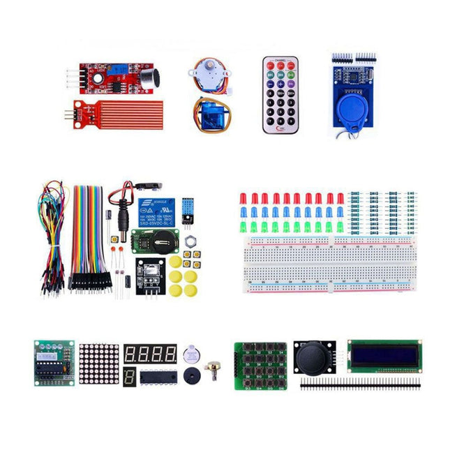
With this kit you can built all the projects described in the book 'Mastering the Arduino Uno R4'. The kit comes with several LEDs, sensors, actuators, and other components. The purpose of the kit is to make a flying start with hardware and software aspects of projects designed around the Arduino Uno microcontroller system.
Included
1x RFID reader module
1x DS1302 clock module
1x 5 V stepper motor
1x '2003' stepper motor drive board
5x Green LED
5x Yellow LED
5x Red LED
2x Rocker switch
1x Flame sensor
1x LM35 sensor module
1x Infrared receiver
3x Light-dependent resistors (LDRs)
1x IR remote controller
1x Breadboard
4x Pushbutton (with four caps)
1x Buzzer
1x Piezo sounder
1x Adjustable resistor (potentiometer)
1x 74HC595 shift register
1x 7-segment display
1x 4-digit 7-segment display
1x 8x8 Dot-matrix display
1x 1602 / I²C LCD module
1x DHT11 Temperature and humidity module
1x Relay module
1x Sound module
Set of Dupont cables
Set of Breadboard cables
1x Water sensor
1x PS2 Joystick
5x 1 k-ohm resistor
5x 10 k-ohm resistor
5x 220-ohm resistor
1x 4x4 keypad module
1x 9g Servo (25 cm)
1x RFID card
1x RGB module
1x 9 V battery DC jack
Not included
Mastering the Arduino Uno R4 (Book)
Arduino Uno R3/R4 (Board)
This CAN Module is based on the CAN bus controller MCP2515 and CAN transceiver TJA1050. With this module, you will easy to control any CAN Bus device by SPI interface with your MCU, such as Arduino Uno and so on. Features Support CAN V2.0B Communication rate up to 1 MB/s Working Voltage: 5 V Working Current: 5 mA Interface: SPI Downloads MCP2515 Datasheet TJA1050 Datasheet
Use your Raspberry Pi with LTE Cat-4 4G/3G/2G Communication & GNSS Positioning, for remote data transmission/phone/SMS, suitable for remote area monitoring/alarming.
This 4G hat is based on the Maduino Zero 4G LTE, but without any controller. It needs to work with Raspberry Pi (2x20 connector and USB). The Raspberry communicate with this HAT with simple AT commands (via the TX/RX Pins in the 2X20 connector) for simple controls, such as SMS/Phone/GNSS; with the USB connecting and proper Linux driver installed, the 4G hat act as a 4G network adapter, that can access to the Internet and transmit data with 4G protocol.
Compares to normal USB 4G dongle, this Raspberry Pi 4G Hat has the following advantages:
Onboard Audio codec, that you can have a call directly with your RPI, or auto broadcasting with a loudspeaker;
Hardware UART communication, hardware controlling of Power(by 2s pulse of PI GPIO or POWERKEY button), hardware controlling of flight mode;
Dual LTE 4G antenna, plus GPS antenna
Features
LTE Cat-4, with uplink rate 50 Mbps and downlink rate 150 Mbps
GNSS Positioning
Audio Driver NAU8810
Supports dial-up, phone, SMS, TCP, UDP, DTMF, HTTP, FTP, and so on
Supports GPS, BeiDou, Glonass, LBS base station positioning
SIM card slot, supports 1.8V/3V SIM card
Onboard audio jack and audio decoder for making a telephone call
2x LED indicators, easy to monitor the working status
Supports SIM application toolkit: SAT Class 3, GSM 11.14 Release 99, USAT
Included
1x 4G LTE Hat For Raspberry Pi
1x GPS antenna
2x 4G LTE antenna
2x Standoff
Downloads
GitHub
Raspberry Pi Pico is a great solution for servo control. With the hardware PIO, the Pico can control the servos by hardware, without usage of times/ interrupts, and limit the usage of the MCU. Driving the six servos on this robotic arm takes very little MCU capacity, so the MCU can deal with other tasks easily. This 6 DOF robotic arm is a handy tool for teaching and learning robotics and Pico usage. There are five MG996s (four are needed in the assembly and one for backup) and three 25-kg servos (two needed in the assembly and one for backup). Note that for the servos the angle ranges from 0° to 180°. All the servos need to be preset to 90° (with logic HIGH 1.5 ms duty) before the assembly to avoid servo damage during movement. This product includes all the necessary items needed to create a robotic arm based on Pico and Micropython. Included 1x Raspberry Pi Pico 1x Raspberry Pi Pico Servo Driver 1x Set '6 DOF Robot Arm' 1x 5 V/5 A Power Supply 2x Backup Servo Downloads GitHub Wiki Assembly Guide Assembly Video
Use acoustic waves to hold in mid-air samples such as water, ants, or tiny electric components. This technology has been previously restricted to a couple of research labs but now you can make it at your home.
Included
76x 10 mm 40 kHz transducers
1x Arduino Nano
1x L298N Dual Motor Drive Board
1x Power Switch
1x DC Adaptor 9 V
1x Jumper Wires
6x Black and Red Wire
Some Exposed Wire
1x 3D-Printed TinyLev
Downloads
Instructables
Scientific Information
This is a soldering kit for the starters to learn soldering. After 1-2 hours soldering and assembly, and easy steps to set the Wifi name/password with a phone, you will get:
A real-time clock, it will get the world real-time from the Network timing protocol, you can set your local time zone easily
An Alarm clock, with loud noise
An Online world weather forecaster, about the local temperature/weather, you can easily change/alter your address/cities without any re-programming
To reduce the soldering difficulty, all the SMD parts have been soldered, you only need to solder the THT parts, and then set the Wifi network with a phone, and finally turn on the power to enjoy the success.
Included
ESP32 SmartClock kit mainboard
Batch of capacitors & resistors/connectors
Colorful LCD module
Lipo battery
Acrylic boards
Nuts & screws
Downloads
User Manual
Source code on GitHub
This is a simple DIY kit using Makerfabs' ESP32-S3 3.5" Parallel TFT with Touch (320x480) and Mabee MLX90640 module to monitor the temperature and display on the screen or save to SD card. It is a nice tool for circuit testing and non-contact temperature sensing.
Features
Based on ESP32-S3, 3.5-inch TFT with capacitive touch
Auto check the highest temperature point
Temperature accuracy: <1°C
Suitable for applications such as human temperature checking or electronic boards debugging
All hardware & software are open, users can modify & add more functions, such WiFi/Bluetooth data transmitting
Downloads
Default firmware
New remote monitoring firmware
Blog
With these jumper wires (length: 20 cm) you can connect a Raspberry Pi or an Arduino with breadboards. Each cable consists of 40 individual wires/pins which can also be separated. Included 1x 40-pins female to female 1x 40-pins male to male 1x 40-pins male to female
This kit is based on ESP32 and LoRa. The ESP32 3.5" display is the console for the system, it receives the LoRa message from LoRa moisture sensors (support up to 8 sensors in the default firmware), and send control commands to LoRa 4-channel MOSFET (2 4-channel MOSFET supported, with totally 8 channels), to control the connected valves open/close, and thus to control the irrigation for multiple points.
Features
Ready to use: Firmware are pre-programmed for all the modules before shipping, the user can only power them up and set the ID to the console, and start to use. Suitable for none-programmers, in 3 minutes to create filed application.
With Lora wireless connection: The monitor & control range can be up to few kilometer, suitable for garden/small farm.
Soil moisture sensor with good corrosion resistance, can be used at least half an year with 2 AAA battery.
Easy to install: Compares to cheap solution with wires, which is hard to implement in files application, there the connection wires do not needed, the whole installation clean and easy; The valves can be connected Lora MOSFET easily.
Hardware & Software Open: To study Lora & FreeRTOS. The ESP32 display console/Lora Soil Moisture Sensor/LoRa MOSFE are all programmed with Arduino. For programmers/engineers, can development further more specialized application.
Based on ESP32, with WiFi connection, the console can also access to internet, the create much more applications including the moisture data updating to internet for remote monitor, and remote control with MQTT.
Included
1x ESP32 3.5' Display (without camera)
1x Lora Expansion for ESP32 Display
2x Lora Moisture Sensor
1x Lora 4-channel MOSFET
1x 12 V Power Supply
Water Pipe (5 m)
1x 1-input & 4-output Pipe Joint
Downloads
Instructable: Soil Monitoring & Irrigation with LoRa
GitHub
Features NFC chip material: PET + Etching antenna Chip: NTAG216 (compatible with all NFC phones) Frequency: 13.56 MHz (High Frequency) Reading time: 1 - 2 ms Storage capacity: 888 bytes Read and write times: > 100,000 times Reading distance: 0 - 5 mm Data retention: > 10 years NFC chip size: Diameter 30 mm Non-contact, no friction, the failure rate is small, low maintenance costs Read rate, verification speed, which can effectively save time and improve efficiency Waterproof, dustproof, anti-vibration No power comes with an antenna, embedded encryption control logic, and communication logic circuit Included 1x NFC Stickers (6-color kit)
NFC is a popular technology in recent years. Almost all the high-end phones in the market support NFC. Near field communication (NFC) is a set of standards for smartphones and similar devices to establish radio communication with each other by touching them together or bringing them into close proximity, usually no more than a few centimeters. This module is built around NXP PN532. NXP PN532 is very popular in the NFC area. Makerfabs developed this module based on the official document. A library for this module is available. Features Small dimension and easy to embed into your project Support I²C, SPI, and HSU (High-Speed UART), easy to change between those modes Support RFID reading and writing, P2P communication with peers, NFC with Android phone Up to 5~7 cm reading distance On-board level shifter, Standard 5 V TTL for I²C and UART, 3.3 V TTL SPI Arduino compatible, plugin and play with our shield RFID reader/writer supports Mifare 1k, 4k, Ultralight, and DESFire cards ISO/IEC 14443-4 cards such as CD97BX, CD light, Desfire, P5CN072 (SMX) Innovision Jewel cards such as IRT5001 cards FeliCa cards such as RCS_860 and RCS_854 Downloads Usage NFC Library
This RC522 RFID Kit includes a 13.56 MHz RF reader module that uses an RC522 IC and two S50 RFID cards to help you learn and add the 13.56 MHz RF transition to your project. The MF RC522 is a highly integrated transmission module for contactless communication at 13.56 MHz. RC522 supports ISO 14443A/MIFARE mode. The module uses SPI to communicate with microcontrollers. The open-hardware community already has a lot of projects exploiting the RC522 – RFID Communication, using Arduino. Features Operating Current: 13-26 mA/DC 3.3 V Idle Current: 10-13 mA/DC 3.3 V Sleep Current: <80 uA Peak Current: <30 mA Operating Frequency: 13.56 MHz Supported card types: mifare1 S50, mifare1 S70 MIFARE Ultralight, Mifare Pro, MIFARE DESFire Environmental Operating Temperature: -20-80 degrees Celsius Environmental Storage Temperature: -40-85 degrees Celsius Relative humidity: relative humidity 5% -95% Reader Distance: ≥50 mm/1.95' (Mifare 1) Module Size: 40×60 mm/1.57*2.34' Module interfaces SPI Parameter Data transfer rate: maximum 10 Mbit/s Included 1x RFID-RC522 Module 1x Standard S50 Blank Card 1x S50 special-shaped card (as shown by the keyring shape) 1x Straight Pin 1x Curved Pin Downloads Arduino Library MFRC522 Datasheet MFRC522_ANT Mifare S50
This air monitor is specifically used for monitoring greenhouses. It detects:
Air temperature & Humidity
CO2 concentration
Light intensity
Then transmit the data via LoRa P2P to the LoRa receiver (on your desk in the room) so that the user can monitor the field status or have it recorded for long-term analysis.
This module monitors the greenhouse field status and sends all sensor data regularly via LoRa P2P in Jason format. This LoRa signal can be received by the Makerfabs LoRa receiver and thus displayed/recorded/analyzed on the PC. The monitoring name/data cycle can be set with a phone, so it can be easily implemented into the file.
This air monitor is powered by an internal LiPo battery charged by a solar panel and can be used for at least 1 year with the default setting (cycle 1 hour).
Features
ESP32S3 module onboard with the WiFi and Bluetooth
Ready to use: Power it on directly to use
Module name/signal interval settable easily by phone
IP68 water-proof
Temperature: -40°C~80°C, ±0.3
Humidity: 0~100% moisture
CO2: 0~1000 ppm
Light intensity: 1-65535 lx
Communication distance: Lora: >3 km
1000 mAh battery, charger IC onboard
Solar panel 6 W, ensure system works
Downloads
Manual
BH1750 Datasheet
SGP30 Datasheet
LoRaWAN is beneficial, but sometimes it is unnecessary, difficult, or expensive to implement a LoRaWAN network, especially when considering cloud integration. For example, monitoring soil moisture in your backyard or tracking conditions in your farm's greenhouse may not require a full LoRaWAN setup.
This LoRa receiver is designed to work with Makerfabs SenseLora modules. It receives LoRa signals and forwards them to a computer, allowing the data to be displayed, recorded, and analyzed on the computer.
Downloads
Manual
Software
The ESP32-S3 Parallel TFT not only offers more SRAM and ROM (compared to the S2 version), but with Bluetooth 5.0 it is also suitable for applications such as local monitoring and controlling.
The built-in LCD driver ILI9488 uses 16-bit parallel lines to communicate with ESP32-S3, the main clock can be up to 20 MHz, which makes the display smooth enough for video displays. With this display, you can create more IoT display projects.
Features
Controller: ESP32-S3-WROOM-1, PCB Antenna, 16 MB Flash, 2 MB PSRAM, ESP32-S3-WROOM-1-N16R2
Wireless: Wifi & Bluetooth 5.0
LCD: 3.5-inch TFT LCD
Resolution: 480x320
Color: RGB
LCD Interface: 16-bit parallel
LCD Driver: ILI9488
Touch Panel: Capacitive
Touch Panel Driver: FT6236
USB: Dual USB Type-C (one for USB-to-UART and one for native USB)
UART to UART Chip: CP2104
Power Supply: USB Type-C 5.0 V (4.0 V~5.25 V)
Button: Flash button and reset button
Mabee Interface: 1x I²C, 1x GPIO
Backlight Controller: Yes
MicroSD: Yes
Arduino support: Yes
Type-C Power Delivery: Not supported
Operation temperature: -40℃ to +85℃
Dimension: 66 x 84.3 x 12 mm
Weight: 52 g
Downloads
ESP32-S3 Datasheet
GitHub
Wiki
LVGL Demo Code
This ESP32 S3 7-inch IPS 5-point capacitive touch display with an ultra-high resolution of 1024 x 600 pixels is ideal for IoT applications. It is ideal for applications such as home automation. An integrated SD card enables recording/playback of stored data. There are also two Mabee/Grove connectors to connect various sensors to this board to create personal prototype projects in no time.
Specifications
Controller: ESP32-S3-WROOM-1, PCB antenna, 16 MB Flash, 8 MB PSRAM, ESP32-S3-WROOM-1-N16R8
Wireless: Wifi & Bluetooth 5.0
LCD: 7-inch High Lightness IPS
FPS: >30
Resolution: 1024 x 600
LCD interface: RGB 565
Touch panel: Capacitive 5-point touch
Touch panel driver: GT911
USB: Dual USB-C (one for USB-to-UART and one for native USB)
UART to UART chip: CP2104
Power supply: USB-C 5.0 V (4.0 V~5.25 V)
Button: Flash button and reset button
Mabee interface: 1x I²C, 1x GPIO
MicroSD: Yes
Arduino support: Yes
Type-C Power Delivery: Not supported
Operation temperature: −40 to +85°C
Downloads
Wiki
GitHub
ESP32-S3 Datasheet
Screen touch coordinates calibration
This display features an IPS resolution of 480x480 with capacitive touch and a frame rate of up to 75 FPS. It is very bright and has 65,000 colors. The mechanical rotary encoder supports clockwise/counterclockwise rotation and also supports the entire pressing process, which can usually be used to confirm the process. The display module is based on ESP32-S3 with WiFi & Bluetooth 5.0 to easily connect to the Internet for IoT projects. It can be powered and programmed directly via the USB port. It also has two expansion ports, I²C and UART. Specifications Controller ESP32-S3 WROOM-1-N16R8 (16 MB Flash, 8 MB PSRAM, PCB antenna) Wireless WiFi & Bluetooth 5.0 Resolution 480x480 LCD 2.1' IPS LCD, 65K color LCD driver ST7701S Frame rate >70 FPS LCD interface RGB 565 Touch panel 5-points capacitive touch Touch panel driver CST8266 USB USB-C native Interfaces 1x I²C, 1x UART (1.25 mm, 4-pin connector) Arduino support Yes Downloads Wiki Usage with Squareline/LVGL GitHub Datasheet_ESP32-S3-WROOM-1