The SparkFun MicroMod mikroBUS Carrier Board takes advantage of the MicroMod, Qwiic, and mikroBUS ecosystems making it easy to rapidly prototype with each of them, combined. The MicroMod M.2 socket and mikroBUS 8-pin header provide users the freedom to experiment with any Processor Board in the MicroMod ecosystem and any Click board in the mikroBUS ecosystem, respectively. This board also features two Qwiic connectors to seamlessly integrate hundreds of Qwiic sensors and accessories into your project. The mikroBUS socket comprises a pair of 8-pin female headers with a standardized pin configuration. The pins consist of three groups of communications pins (SPI, UART and I²C), six additional pins (PWM, Interrupt, Analog input, Reset and Chip select), and two power groups (3.3 V and 5 V). While a modern USB-C connector makes programming easy, the Carrier Board is also equipped with a MCP73831 Single-Cell Lithium-Ion/Lithium-Polymer Charge IC so you can charge an attached single-cell LiPo battery. The charge IC receives power from the USB connection and can source up to 450 mA to charge an attached battery. Features M.2 MicroMod (Processor Board) Connector USB-C Connector 3.3 V 1 A Voltage Regulator 2x Qwiic Connectors mikroBUS Socket Boot/Reset Buttons Charge Circuit JTAG/SWD PTH Pins Downloads Schematic Eagle Files Board Dimensions Hookup Guide Getting Started with Necto Studio mikroBUS Standard Qwiic Info Page GitHub Hardware Repo
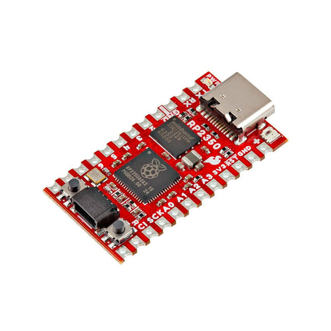
The SparkFun RP2350 Pro Micro provides a powerful development platform, built around the RP2350 microcontroller. This board uses the updated Pro Micro form factor. It includes a USB-C connector, Qwiic connector, WS2812B addressable RGB LED, Boot and Reset buttons, resettable PTC fuse, and PTH and castellated solder pads.
The RP2350 is a unique dual-core microcontroller with two ARM Cortex-M33 processors and two Hazard3 RISC-V processors, all running at up to 150 MHz! Now, this doesn't mean the RP2350 is a quad-core microcontroller. Instead, users can select which two processors to run on boot instead. You can run two processors of the same type or one of each. The RP2350 also features 520 kB SRAM in ten banks, a host of peripherals including two UARTs, two SPI and two I²C controllers, and a USB 1.1 controller for host and device support.
The Pro Micro also includes two expanded memory options: 16 MB of external Flash and 8 MB PSRAM connected to the RP2350's QSPI controller. The RP2350 Pro Micro works with C/C++ using the Pico SDK, MicroPython, and Arduino development environments.
Features
RP2350 Microcontroller
8 MB PSRAM
16 MB Flash
Supply Voltage
USB: 5 V
RAW: 5.3 V (max.)
Pro Micro Pinout
2x UART
1x SPI
10x GPIO (4 used for UART1 and UART0)
4x Analog
USB-C Connector
USB 1.1 Host/Device Support
Qwiic Connector
Buttons
Reset
Boot
LEDs
WS2812 Addressable RGB LED
Red Power LED
Dimensions: 33 x 17.8 mm
Downloads
Schematic
Eagle Files
Board Dimensions
Hookup Guide
RP2350 MicroPython Firmware (Beta 04)
SparkFun Pico SDK Library
Arduino Pico Arduino Core
Datasheet (RP2350)
Datasheet (APS6404L PSRAM)
RP2350 Product Brief
Raspberry Pi RP2350 Microcontroller Documentation
Qwiic Info Page
GitHub Repository
The full-color, spiral-bound SIK guidebook (included) contains step-by-step instructions with circuit diagrams and hookup tables for building each project and circuit with the included parts. Full example code is provided, new concepts and components are explained at the point of use, and troubleshooting tips offer assistance if something goes wrong.
The kit does not require any soldering and is recommended for beginners ages 10 and up looking for an Arduino starter kit. For SIK version 4.1, Sparkfun took an entirely different approach to teaching embedded electronics. In previous versions of the SIK, each circuit focused on introducing a new piece of technology. With SIK v4.1, components are introduced in the context of the circuit you are building. Each circuit builds upon the last, leading up to a project that incorporates all of the components and concepts introduced throughout the guide. With new parts and a completely new strategy, even if you've used the SIK before, you're in for a brand-new experience!
The SIK V4.1 includes the Redboard Qwiic, which allows you to expand into the SparkFun Qwiic ecosystem after becoming proficient with the SIK circuits. The SparkFun Qwiic Connect System is an ecosystem of I²C sensors, actuators, shields and cables that make prototyping faster and less prone to error. All Qwiic-enabled boards use a common 1mm pitch, 4-pin JST connector. This reduces the amount of required PCB space, and polarized connections mean you can’t hook it up wrong. With the addition of the SparkFun RedBoard Qwiic, you will need to download a new driver install that is different from the original SparkFun RedBoard.
Included
SparkFun RedBoard Qwiic
Arduino and Breadboard Holder
SparkFun Inventor's Kit Guidebook
White Solderless Breadboard
Carrying Case
SparkFun Mini Screwdriver
16 x 2 White-on-Black LCD (with headers)
SparkFun Motor Driver (with Headers)
Pair of Rubber Wheels
Pair of Hobby Gearmotors
Small Servo
Ultrasonic Distance Sensor
TMP36 Temp Sensor
6' USB Micro-B Cable
Jumper Wires
Photocell
Tricolour LED
Red, Blue, Yellow and Green LEDs
Red, Blue, Yellow and Green Tactile Buttons
10K Trimpot
Mini Power Switch
Piezo Speaker
AA Battery Holder
330 and 10K Resistors
Binder Clip
Dual-Lock Fastener
The flexibility of the Artemis module starts with SparkFun's Arduino core. You can program and use the Artemis module just like you would an Uno or any other Arduino. The time to first blink is just 5 minutes away! We built the core from the ground up, making it fast and as lightweight as possible.
Next is the module itself. Measuring 10 x 15 mm, the Artemis module has all the support circuitry you need to use the fantastic Ambiq Apollo3 processor in your next project. We're proud to say the SparkFun Artemis module is the first open-source hardware module with the design files freely and easily available. We've carefully designed the module so that implementing Artemis into your design can be done with low-cost 2-layer PCBs and 8mil trace/space.
Made in the USA at SparkFun's Boulder production line, the Artemis module is designed for consumer-grade products. This truly differentiates the Artemis from its Arduino brethren. Ready to scale your product? The Artemis will grow with you beyond the Uno footprint and Arduino IDE. Additionally, the Artemis has an advanced HAL (hardware abstraction layer), allowing users to push the modern Cortex-M4F architecture to its limit.
The SparkFun Artemis Module is fully FCC/IC/CE certified and is available in full tape and reel quantities. With 1M flash and 384k RAM, you'll have plenty of room for your code. The Artemis module runs at 48MHz with a 96MHz turbo mode available and with Bluetooth to boot!
The SparkFun Thing Plus Matter is the first easily accessible board of its kind that combines Matter and SparkFun’s Qwiic ecosystem for agile development and prototyping of Matter-based IoT devices. The MGM240P wireless module from Silicon Labs provides secure connectivity for both 802.15.4 with Mesh communication (Thread) and Bluetooth Low Energy 5.3 protocols. The module comes ready for integration into Silicon Labs' Matter IoT protocol for home automation.
What is Matter? Simply put, Matter allows for consistent operation between smart home devices and IoT platforms without an Internet connection, even from different providers. In doing so, Matter is able to communicate between major IoT ecosystems in order to create a single wireless protocol that is easy, reliable, and secure to use.
The Thing Plus Matter (MGM240P) includes Qwiic and LiPo battery connectors, and multiple GPIO pins capable of complete multiplexing through software. The board also features the MCP73831 single-cell LiPo charger as well as the MAX17048 fuel gauge to charge and monitor a connected battery. Lastly, a µSD card slot for any external memory needs is integrated.
The MGM240P wireless module is built around the EFR32MG24 Wireless SoC with a 32-bit ARM Cortext-M33 core processor running at 39 MHz with 1536 kb Flash memory and 256 kb RAM. The MGM240P works with common 802.15.4 wireless protocols (Matter, ZigBee, and OpenThread) as well as Bluetooth Low Energy 5.3. The MGM240P supports Silicon Labs' Secure Vault for Thread applications.
Specifications
MGM240P Wireless Module
Built around the EFR32MG24 Wireless SoC
32-bit ARM-M33 Core Processor (@ 39 MHz)
1536 kB Flash Memory
256 kB RAM
Supports Multiple 802.15.4 Wireless Protocols (ZigBee and OpenThread)
Bluetooth Low Energy 5.3
Matter-ready
Secure Vault Support
Built-in Antenna
Thing Plus Form-Factor (Feather-compatible):
Dimensions: 5.8 x 2.3 cm (2.30 x 0.9')
2 Mounting Holes:
4-40 screw compatible
21 GPIO PTH Breakouts
All pins have complete multiplexing capability through software
SPI, I²C and UART interfaces mapped by default to labeled pins
13 GPIO (6 labeled as Analog, 7 labeled for GPIO)
All function as either GPIO or Analog
Built-in-Digital to Analog Converter (DAC)
USB-C Connector
2-Pin JST LiPo Battery Connector for a LiPo Battery (not included)
4-Pin JST Qwiic Connector
MC73831 Single-Cell LiPo Charger
Configurable charge rate (500 mA Default, 100 mA Alternate)
MAX17048 Single-Cell LiPo Fuel Gauge
µSD Card Slot
Low Power Consumption (15 µA when MGM240P is in Low Power Mode)
LEDs:
PWR – Red Power LED
CHG – Yellow battery charging status LED
STAT – Blue status LED
Reset Button:
Physical push-button
Reset signal can be tied to A0 to enable use as a peripheral device
Downloads
Schematic
Eagle Files
Board Dimensions
Hookup Guide
Datasheet (MGM240P)
Fritzing Part
Thing+ Comparison Guide
Qwiic Info Page
GitHub Hardware Repo
The Qwiic pHAT connects the I²C bus (GND, 3.3V, SDA, and SCL) on your Raspberry Pi to an array of Qwiic connectors on the HAT. Since the Qwiic system allows for daisy-chaining boards with different addresses, you can stack as many sensors as you’d like to create a tower of sensing power! The Qwiic pHAT V2.0 has four Qwiic connect ports (two on its side and two vertical), all on the same I²C bus. We've also made sure to add a simple 5V screw terminal to power boards that may need more than 3.3V and a general-purpose button (with the option to shut down the Pi with a script). Also updated, the mounting holes found on the board are now spaced to accommodate the typical Qwiic board dimension of 1.0' x 1.0'. This HAT is compatible with any Raspberry Pi that utilizes the standard 2x20 GPIO header and the NVIDIA Jetson Nano and Google Coral. Features 4 x Qwiic Connection Ports 1 x 5V Tolerant Screw Terminal 1 x General Purpose Button HAT-compatible 40-pin Female Header
The SparkFun Weather Shield uses the Si7021 humidity / temperature sensor, the MPL3115A2 barometric pressure sensor, and the ALS-PT19 light sensor. The shield utilizes the MPL3115A2 and Si7021 Arduino libraries.
The SparkFun Weather Shield comes with two unpopulated RJ11 connector spaces and a 6-pin GPS connector. Finally, each Weather Shield can operate from 3.3 V up to 16 V and has built-in voltage regulators and signal translators.
Check out the GitHub page, Schematics, and Eagle Files for more information.
The SparkFun Qwiic OpenLog is the smarter and better looking cousin to the extremely popular OpenLog but now we've ported the original serial based interface to I²C! Thanks to the added Qwiic connectors, you can daisy chain multiple I²C devices and log them all without taking up your serial port. The Qwiic OpenLog can store, or 'log', huge amounts of serial data and act as a black box of sorts to store all the data that your project generates, for scientific or debugging purposes. Utilizing our handy Qwiic system, no soldering is required to connect it to the rest of your system. However, we still have broken out 0.1'-spaced pins in case you prefer to use a breadboard. Like its predecessor, the SparkFun Qwiic OpenLog runs off of an onboard ATmega328, running at 16 MHz thanks to the onboard resonator. The ATmega328 has been sure to feature the Optiboot bootloader loaded, which allows the OpenLog to be compatible with the “Arduino Uno” board setting in the Arduino IDE. It is important to be aware that the Qwiic OpenLog draws approximately 2 mA-6 mA in idle (nothing to record) mode, however, during a full record the OpenLog can draw 20 mA to 23 mA depending on the microSD card being used. The Qwiic OpenLog also supports clock stretching, which means it performs even better than the original and will record data up to 20,000 bytes per second at 400 kHz. As the receive buffer fills up this OpenLog will hold the clock line, letting the master know that it is busy. Once the Qwiic OpenLog is finished with a task, it releases the clock thus allowing the data to continue flowing without corruption. For even better performance the OpenLog Artemis is the tool you need, featuring logging speeds up to 500000 bps. Features Continuous data logging at 20,000 bytes per second without corruption Compatible with high speed 400 kHz I²C Compatible with 64 MB to 32 GB microSD cards (FAT16 or FAT32) Preloaded Uno bootloader so upgrading the firmware is as easy as loading a new sketch Valid I²C Addresses: 0x08 to 0x77 2x Qwiic Connectors Downloads Schematic Eagle Files Hookup Guide Arduino Library GitHub
The RP2040 utilizes dual ARM Cortex-M0+ processors (up to 133MHz): 264kB of embedded SRAM in six banks 6 dedicated IO for SPI Flash (supporting XIP) 30 multifunction GPIO: Dedicated hardware for commonly used peripherals Programmable IO for extended peripheral support Four 12-bit ADC channels with internal temperature sensor (up to 0.5 MSa/s) USB 1.1 Host/Device functionality The RP2040 is supported with C/C++ and MicroPython cross-platform development environments, including easy access to runtime debugging. It has a UF2 boot and floating-point routines baked into the chip. The built-in USB can act as both device and host. It has two symmetric cores and high internal bandwidth, making it useful for signal processing and video. While the chip has a large internal RAM, the board includes an additional external flash chip. Features Dual Cortex M0+ processors, up to 133 MHz 264 kB of embedded SRAM in 6 banks 6 dedicated IO for QSPI flash, supporting execute in place (XIP) 30 programmable IO for extended peripheral support SWD interface Timer with 4 alarms Real-time counter (RTC) USB 1.1 Host/Device functionality Supported programming languages MicroPython C/C++
The SparkFun RedBoard Qwiic is an Arduino-compatible board that combines features of different Arduinos with the Qwiic Connect System.
Features
ATmega328 microcontroller with Optiboot Bootloader
R3 Shield Compatible
CH340C Serial-USB Converter
3.3 V to 5 V Voltage Level Jumper
A4 / A5 Jumpers
AP2112 Voltage Regulator
ISP Header
Input voltage: 7 V - 15 V
1 Qwiic Connector
16 MHz Clock Speed
32 k Flash Memory
All SMD Construction
Improved Reset Button
The Qwiic Mux also has eight configurable addresses of its own, allowing for up to 64 I²C buses on a connection. To make it even easier to use this multiplexer, all communication is enacted exclusively via I²C, utilizing our handy Qwiic system. The Qwiic Mux also allows you to change the last three bits of the address byte, allowing for eight jumper selectable addresses if you happen to need to put more than one Qwiic Mux Breakout on the same I²C port. The address can be changed by adding solder to any of the three ADR jumpers. Each SparkFun Qwiic Mux Breakout operates between 1.65 V and 5.5 V, making it ideal for all of the Qwiic boards we produce in house.
Plug a reader into the headers, use a Qwiic cable, scan your 125kHz ID tag, and the unique 32-bit ID will be shown on the screen. The unit comes with a read LED and buzzer, but don't worry, there is a jumper you can cut to disable the buzzer if you want. Utilizing SparkFun's handy Qwiic system, no soldering is required to connect it to the rest of your system. However, we still have broken out 0.1"-spaced pins if you prefer to use a breadboard.
Utilizing the onboard ATtiny84A, the Qwiic RFID takes the six byte ID tag of your 125kHz RFID card, attaches a timestamp to it, and puts it onto a stack that holds up to 20 unique RFID scans at a time. This information is easy to get at with some simple I²C commands.