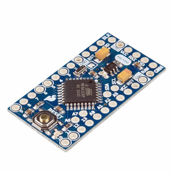
The Arduino Pro Mini is a microcontroller board based on the ATmega328P.
It has 14 digital input/output pins (of which 6 can be used as PWM outputs), 6 analog inputs, an on-board resonator, a reset button, and holes for mounting pin headers. A six pin header can be connected to an FTDI cable or SparkFun breakout board to provide USB power and communication to the board.
The Arduino Pro Mini is intended for semi-permanent installation in objects or exhibitions. The board comes without pre-mounted headers, allowing the use of various types of connectors or direct soldering of wires. The pin layout is compatible with the Arduino Mini.
The Arduino Pro Mini was designed and is manufactured by SparkFun Electronics.
Specifications
Microcontroller
ATmega328P
Board Power Supply
5-12 V
Circuit Operating Voltage
5 V
Digital I/O Pins
14
PWM Pins
6
UART
1
SPI
1
I²C
1
Analog Input Pins
6
External Interrupts
2
DC Current per I/O Pin
40 mA
Flash Memory
32 KB of which 2 KB used by bootloader
SRAM
2 KB
EEPROM
1 KB
Clock Speed
16 MHz
Dimensions
18 x 33.3 mm (0.7 x 1.3")
Downloads
Eagle files
Schematics
The RedBoard Artemis has the improved power conditioning and USB to serial that we've refined over the years on our RedBoard line of products. A modern USB-C connector makes programming easy. A Qwiic connector makes I²C easy. The RedBoard Artemis is fully compatible with SparkFun's Arduino core and can be programmed easily under the Arduino IDE. We've exposed the JTAG connector for more advanced users who prefer to use professional tools' power and speed. We've added a digital MEMS microphone for folks wanting to experiment with always-on voice commands with TensorFlow and machine learning. We've even added a convenient jumper to measure current consumption for low power testing.
With 1MB flash and 384k RAM, you'll have plenty of room for your sketches. The on-board Artemis module runs at 48MHz with a 96MHz turbo mode available and with Bluetooth to boot!
Features
Arduino Uno R3 Footprint
1M Flash / 384k RAM
48MHz / 96MHz turbo available
24 GPIO - all interrupt capable
21 PWM channels
Built-in BLE radio
10 ADC channels with 14-bit precision
2 UARTs
6 I²C buses
4 SPI buses
PDM Interface
I²S Interface
Qwiic Connector
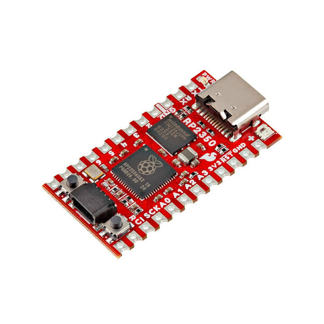
The SparkFun RP2350 Pro Micro provides a powerful development platform, built around the RP2350 microcontroller. This board uses the updated Pro Micro form factor. It includes a USB-C connector, Qwiic connector, WS2812B addressable RGB LED, Boot and Reset buttons, resettable PTC fuse, and PTH and castellated solder pads.
The RP2350 is a unique dual-core microcontroller with two ARM Cortex-M33 processors and two Hazard3 RISC-V processors, all running at up to 150 MHz! Now, this doesn't mean the RP2350 is a quad-core microcontroller. Instead, users can select which two processors to run on boot instead. You can run two processors of the same type or one of each. The RP2350 also features 520 kB SRAM in ten banks, a host of peripherals including two UARTs, two SPI and two I²C controllers, and a USB 1.1 controller for host and device support.
The Pro Micro also includes two expanded memory options: 16 MB of external Flash and 8 MB PSRAM connected to the RP2350's QSPI controller. The RP2350 Pro Micro works with C/C++ using the Pico SDK, MicroPython, and Arduino development environments.
Features
RP2350 Microcontroller
8 MB PSRAM
16 MB Flash
Supply Voltage
USB: 5 V
RAW: 5.3 V (max.)
Pro Micro Pinout
2x UART
1x SPI
10x GPIO (4 used for UART1 and UART0)
4x Analog
USB-C Connector
USB 1.1 Host/Device Support
Qwiic Connector
Buttons
Reset
Boot
LEDs
WS2812 Addressable RGB LED
Red Power LED
Dimensions: 33 x 17.8 mm
Downloads
Schematic
Eagle Files
Board Dimensions
Hookup Guide
RP2350 MicroPython Firmware (Beta 04)
SparkFun Pico SDK Library
Arduino Pico Arduino Core
Datasheet (RP2350)
Datasheet (APS6404L PSRAM)
RP2350 Product Brief
Raspberry Pi RP2350 Microcontroller Documentation
Qwiic Info Page
GitHub Repository
The RP2040 contains two ARM Cortex-M0+ processors (up to 133 MHz) and features:
264 kB of embedded SRAM in six banks
6 dedicated IO for SPI Flash (supporting XIP)
30 multifunction GPIO:
Dedicated hardware for commonly used peripherals
Programmable IO for extended peripheral support
Four 12-bit ADC channels with internal temperature sensor (up to 0.5 MSa/s)
USB 1.1 Host/Device functionality
The RP2040 is supported with C/C++ and MicroPython cross-platform development environments, including easy access to runtime debugging. It has a UF2 boot and floating-point routines baked into the chip. While the chip has a large internal RAM, the board includes an additional 16 MB of external QSPI flash memory to store program code.
Features
Raspberry Pi Foundation's RP2040 microcontroller
16MB QSPI Flash Memory
JTAG PTH Pins
Thing Plus (or Feather) Form-Factor:
18x Multifunctional GPIO Pins
Four available 12-bit ADC channels with an internal temperature sensor (500 kSa/s)
Up to eight 2-channel PWM
Up to two UARTs
Up to two I²C buses
Up to two SPI buses
USB-C Connector:
USB 1.1 Host/Device functionality
2-pin JST Connector for a LiPo Battery (not included):
500 mA charging circuit
Qwiic Connector
Buttons:
Boot
Reset
LEDs:
PWR - Red 3.3 V power indicator
CHG - Yellow battery charging indicator
25 - Blue status/test LED (GPIO 25)
WS2812 - Addressable RGB LED (GPIO 08)
Four Mounting Holes:
4-40 screw compatible
Dimensions: 2.3' x 0.9'
RP2040 Features
Dual Cortex M0+ processors, up to 133 MHz
264 kB of embedded SRAM in 6 banks
6 dedicated IO for QSPI flash, supporting execute in place (XIP)
30 programmable IO for extended peripheral support
SWD interface
Timer with 4 alarms
Real-time counter (RTC)
USB 1.1 Host/Device functionality
Supported programming languages
MicroPython
C/C++
The flexibility of the Artemis module starts with SparkFun's Arduino core. You can program and use the Artemis module just like you would an Uno or any other Arduino. The time to first blink is just 5 minutes away! We built the core from the ground up, making it fast and as lightweight as possible.
Next is the module itself. Measuring 10 x 15 mm, the Artemis module has all the support circuitry you need to use the fantastic Ambiq Apollo3 processor in your next project. We're proud to say the SparkFun Artemis module is the first open-source hardware module with the design files freely and easily available. We've carefully designed the module so that implementing Artemis into your design can be done with low-cost 2-layer PCBs and 8mil trace/space.
Made in the USA at SparkFun's Boulder production line, the Artemis module is designed for consumer-grade products. This truly differentiates the Artemis from its Arduino brethren. Ready to scale your product? The Artemis will grow with you beyond the Uno footprint and Arduino IDE. Additionally, the Artemis has an advanced HAL (hardware abstraction layer), allowing users to push the modern Cortex-M4F architecture to its limit.
The SparkFun Artemis Module is fully FCC/IC/CE certified and is available in full tape and reel quantities. With 1M flash and 384k RAM, you'll have plenty of room for your code. The Artemis module runs at 48MHz with a 96MHz turbo mode available and with Bluetooth to boot!
The SparkFun MicroMod mikroBUS Carrier Board takes advantage of the MicroMod, Qwiic, and mikroBUS ecosystems making it easy to rapidly prototype with each of them, combined. The MicroMod M.2 socket and mikroBUS 8-pin header provide users the freedom to experiment with any Processor Board in the MicroMod ecosystem and any Click board in the mikroBUS ecosystem, respectively. This board also features two Qwiic connectors to seamlessly integrate hundreds of Qwiic sensors and accessories into your project. The mikroBUS socket comprises a pair of 8-pin female headers with a standardized pin configuration. The pins consist of three groups of communications pins (SPI, UART and I²C), six additional pins (PWM, Interrupt, Analog input, Reset and Chip select), and two power groups (3.3 V and 5 V). While a modern USB-C connector makes programming easy, the Carrier Board is also equipped with a MCP73831 Single-Cell Lithium-Ion/Lithium-Polymer Charge IC so you can charge an attached single-cell LiPo battery. The charge IC receives power from the USB connection and can source up to 450 mA to charge an attached battery. Features M.2 MicroMod (Processor Board) Connector USB-C Connector 3.3 V 1 A Voltage Regulator 2x Qwiic Connectors mikroBUS Socket Boot/Reset Buttons Charge Circuit JTAG/SWD PTH Pins Downloads Schematic Eagle Files Board Dimensions Hookup Guide Getting Started with Necto Studio mikroBUS Standard Qwiic Info Page GitHub Hardware Repo
Voice recognition, always-on voice commands, gesture, or image recognition are possible with TensorFlow applications. The cloud is impressively robust, but all-the-time connection requires power and connectivity that may not be available. Edge computing handles discrete tasks such as determining if someone said 'yes' and responds accordingly. The audio analysis is done on the MicroMod combination rather than on the web. This dramatically reduces costs and complexity while limiting potential data privacy leaks.
This board features two MEMS microphones (one with a PDM interface, one with an I²S interface), an ST LIS2DH12 3-axis accelerometer, a connector to interface to a camera (sold separately), and a Qwiic connector. A modern USB-C connector makes programming easy and we've exposed the JTAG connector for more advanced users who prefer to use the power and speed of professional tools. We've even added a convenient jumper to measure current consumption for low power testing.
Features
M.2 MicroMod Keyed-E H4.2mm 65 pins SMD Connector 0.5mm
Digital I²C MEMS Microphone PDM Invensense ICS-43434 (COMP)
Digital PDM MEMS Microphone PDM Knowles SPH0641LM4H-1 (IC)
ML414H-IV01E Lithium Battery for RTC
ST LIS2DH12TR Accelerometer (3-axis, ultra-low-power)
24 Pin 0.5mm FPC Connector (Himax camera connector)
USB-C
Qwiic connector
MicroSD socket
Phillips #0 M2.5x3mm screw included
The SparkFun RP2040 mikroBUS Development Board is a low-cost, high performance platform with flexible digital interfaces featuring the Raspberry Pi Foundation's RP2040 microcontroller. Besides the Thing Plus or Feather PTH pin layout, the board also includes a microSD card slot, 16 MB (128 Mbit) flash memory, a JST single cell battery connector (with a charging circuit and fuel gauge sensor), an addressable WS2812 RGB LED, JTAG PTH pins, four (4-40 screw) mounting holes, our signature Qwiic connectors, and a mikroBUS socket. The mikroBUS standard was developed by MikroElektronika. Similar to Qwiic and MicroMod interfaces, the mikroBUS socket provides a standardized connection for add-on Click boards to be attached to a development board and is comprised of a pair of 8-pin female headers with a standardized pin configuration. The pins consist of three groups of communications pins (SPI, UART and I²C), six additional pins (PWM, Interrupt, Analog input, Reset and Chip select), and two power groups (3.3 V and 5 V). The RP2040 is supported with both C/C++ and MicroPython cross-platform development environments, including easy access to runtime debugging. It has UF2 boot and floating-point routines baked into the chip. While the chip has a large amount of internal RAM, the board includes an additional 16 MB of external QSPI flash memory to store program code. The RP2040 contains two ARM Cortex-M0+ processors (up to 133 MHz) and features: 264 kB of embedded SRAM in six banks 6 dedicated IO for SPI Flash (supporting XIP) 30 multifunction GPIO: Dedicated hardware for commonly used peripherals Programmable IO for extended peripheral support Four 12-bit ADC channels with internal temperature sensor (up to 0.5 MSa/s) USB 1.1 Host/Device functionality Features (SparkFun RP2040 mikroBUS Dev. Board) Raspberry Pi Foundation's RP2040 microcontroller 18 Multifunctional GPIO Pins Four available 12-bit ADC channels with internal temperature sensor (500kSa/s) Up to eight 2-channel PWM Up to two UARTs Up to two I²C buses Up to two SPI buses Thing Plus (or Feather) Pin Layout: 28 PTH Pins USB-C Connector: USB 1.1 Host/Device functionality 2-pin JST Connector for a LiPo Battery (not included): 500mA charging circuit 4-pin JST Qwiic Connector LEDs:
PWR - Red 3.3V power indicator
CHG - Yellow battery charging indicator
25 - Blue status/test LED (GPIO 25)
WS2812 - Addressable RGB LED (GPIO 08) Buttons: Boot Reset JTAG PTH Pins 16MB QSPI Flash Memory µSD Card Slot mikroBUS Socket Dimensions: 3.7' x 1.2' Four Mounting Holes: 4-40 screw compatible Downloads Schematic Eagle Files Board Dimensions Hookup Guide Qwiic Info Page GitHub Hardware Repository
This module includes an integrated trace antenna, fits the IC to an FCC-approved footprint, and includes decoupling and timing mechanisms that would need to be designed into a circuit using the bare nRF52840 IC. The Bluetooth transceiver included on the nRF52840 boasts a BT 5.1 stack. It supports Bluetooth 5, Bluetooth mesh, IEEE 802.15.4 (Zigbee & Thread) and 2.4Ghz RF wireless protocols (including Nordic's proprietary RF protocol) allowing you to pick which option works best for your application.
Features
ARM Cortex-M4 CPU with a floating-point unit (FPU)
1MB internal Flash -- For all of your program, SoftDevice, and file-storage needs!
256kB internal RAM -- For your stack and heap storage.
Integrated 2.4GHz radio with support for:
Bluetooth Low Energy (BLE) -- With peripheral and/or central BLE device support
Bluetooth 5 -- Mesh Bluetooth!
ANT -- If you want to turn the device into a heart-rate or exercise monitor.
Nordic's proprietary RF protocol -- If you want to communicate, securely, with other Nordic devices.
Every I/O peripheral you could need.
USB -- Turn your nRF52840 into a USB mass-storage device, use a CDC (USB serial) interface, and more.
UART -- Serial interfaces with support for hardware flow-control if desired.
I²C -- Everyone's favourite 2-wire bi-directional bus interface
SPI -- If you prefer the 3+-wire serial interface
Analogue-to-digital converters (ADC) -- Eight pins on the nRF52840 Mini Breakout support analogue inputs
PWM -- Timer support on any pin means PWM support for driving LEDs or servo motors.
Real-time clock (RTC) -- Keep close track of seconds and milliseconds, also supports timed deep-sleep features.
Three UARTs
Primary tied to USB interface. Two hardware UARTs.
Two I²C Buses
Two SPI Buses
Secondary SPI Bus primarily used for Flash IC.
PDM Audio Processing
Two Analog Inputs
Two Dedicated Digital I/O Pins
Two Dedicated PWM Pins
Eleven General Purpose I/O Pins
The Power Delivery Board uses a standalone controller to negotiate with the power adapters and switch to a higher voltage other than just 5V. This uses the same power adapter for different projects rather than relying on multiple power adapters to provide different output; it can deliver the board as part of SparkFun’s Qwiic connect system, so you won’t have to do any soldering to figure out how things are oriented.
The SparkFun Power Delivery Board takes advantage of the power delivery standard using a standalone controller from STMicroelectronics, the STUSB4500. The STUSB4500 is a USB power delivery controller that addresses sink devices. It implements a proprietary algorithm to negotiate a power delivery contract with a source (i.e. a power delivery wall wart or power adapter) without the need for an external microcontroller. However, you will need a microcontroller to configure the board. PDO profiles are configured in an integrated non-volatile memory. The controller does all the heavy lifting of power negotiation and provides an easy way to configure over I²C.
To configure the board, you will need an I²C bus. The Qwiic system makes it easy to connect the Power Delivery board to a microcontroller. Depending on your application, you can also connect to the I²C bus via the plated through SDA and SCL holes.
Features
Input and output voltage range of 5-20V
Output current up to 5A
Three configurable power delivery profiles
Auto-run Type-C™ and USB PD sink controller
Certified USB Type-C™ rev 1.2 and USB PD rev 2.0 (TID #1000133)
Integrated VBUS voltage monitoring
Integrated VBUS switch gate drivers (PMOS)
The SparkFun RedBoard Qwiic is an Arduino-compatible board that combines features of different Arduinos with the Qwiic Connect System.
Features
ATmega328 microcontroller with Optiboot Bootloader
R3 Shield Compatible
CH340C Serial-USB Converter
3.3 V to 5 V Voltage Level Jumper
A4 / A5 Jumpers
AP2112 Voltage Regulator
ISP Header
Input voltage: 7 V - 15 V
1 Qwiic Connector
16 MHz Clock Speed
32 k Flash Memory
All SMD Construction
Improved Reset Button
Reinforcing its commitment to widening the accessibility to and innovation in the area of deep learning, NVIDIA has created a free, self-paced, online Deep Learning Institute (DLI) course, “Getting Started on AI with Jetson Nano.” The course's goal is to build foundational skills to enable anyone to get creative with the Jetson Developer Kit. Please be aware that this kit is for those who already own a Jetson Nano Developer Kit and want to join the DLI Course. A Jetson Nano is not included in this kit.
Included in this kit is everything you will need to get started in the “Getting Started on AI with Jetson Nano” (except for a Jetson Nano, of course), and you will learn how to
Set up your Jetson Nano and camera
Collect image data for classification models
Annotate image data for regression models
Train a neural network on your data to create your own models
Run inference on the Jetson Nano with the models you create
The NVIDIA Deep Learning Institute offers hands-on training in AI and accelerated computing to solve real-world problems. Developers, data scientists, researchers, and students can get practical experience powered by GPUs in the cloud and earn a competency certificate to support professional growth. They offer self-paced, online training for individuals, instructor-led workshops for teams, and downloadable course materials for university educators.
Included
32 GB microSD Card
Logitech C270 Webcam
Power Supply 5 V, 4 A
USB Cable - microB (Reversible)
2-Pin Jumper
Please note: Jetson Nano Developer Kit not included.