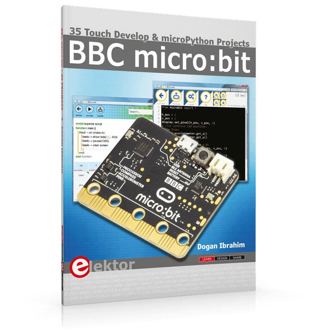
35 Touch Develop & MicroPython Projects
The BBC micro:bit is a credit sized computer based on a highly popular and high performance ARM processor. The device is designed by a group of 29 partners for use in computer education in the UK and will be given free of charge to every secondary school student in the UK.
The device is based on the Cortex-M0 processor and it measures 4 x 5 cm. It includes several important sensors and modules such as an accelerometer, magnetometer, 25 LEDs, 2 programmable push-button switches, Bluetooth connectivity, micro USB socket, 5 ring type connectors, and a 23-pin edge connector. The device can be powered from its micro USB port by connecting it to a PC, or two external AAA type batteries can be used.
This book is about the use of the BBC micro:bit computer in practical projects. The BBC micro:bit computer can be programmed using several different programming languages, such as Microsoft Block Editor, Microsoft Touch Develop, MicroPython, and JavaScript.
The book makes a brief introduction to the Touch Develop programming language and the MicroPython programming language. It then gives 35 example working and tested projects using these language. Readers who learn to program in Touch Develop and MicroPython should find it very easy to program using the Block Editor or any other languages.
The following are given for each project:
Title of the project
Description of the project
Aim of the project
Touch Develop and MicroPython program listings
Complete program listings are given for each project. In addition, working principles of the projects are described briefly in each section. Readers are encouraged to go through the projects in the order given in the book.
The QA403 is QuantAsylum's fourth-generation audio analyzer. The QA403 extends the functionality of the QA402 with improved noise and distortion performance, in addition to a flatter response at band edges. The compact size of the QA403 means you can take it just about anywhere.
Features
24-bit ADC/DAC
Up to 192 kS/s
Fully isolated from PC
Differential Input/Output
USB powered
Built-in Attenuator
Fast Bootup and Driverless
The QA403 is a driverless USB device, meaning it’s ready as soon as you plug it in. The software is free and it is quick and easy to move the hardware from one machine to the next. So, if you need to head to the factory to troubleshoot a problem or take the QA403 home for a work-from-home day, you can do it without hassle.
No-Cal Design
The QA403 comes with a factory calibration in its flash memory, ensuring consistent unit-to-unit performance. On your manufacturing line you can install another QA403 and be confident what you read on one unit will be very similar to the next unit. It is not expected that re-calibration will be required at regular intervals.
Measurements
Making basic measurements is quick and easy. In a few clicks you will understand the frequency response, THD(+N), gain, SNR and more of your device-under test.
Dynamic Range
The QA403 offers 8 gain ranges on the input (0 to +42 dBV in 6 steps), and 4 gain ranges on the output (-12 to +18 dBV in 10 dB steps). This ensures consistent performance over very wide ranges of input and output levels. The maximum AC input to the QA403 is +32 dBV = 40 Vrms. The maximum DC is ±40 V, and the maximum ACPEAK + DC = ±56 V.
Easy Programmability
The QA403 supports a REST interface, making it easy to automate measurements in just about any language you might anticipate. From Python to C++ to Visual Basic—if you know how to load a web page in your favorite language, you can control the QA403 remotely. Measurements are fast and responsive, usually with dozens of commands being processed per second.
Isolated and USB Powered
The QA403 is isolated from the PC, meaning you are measuring your DUT and not chasing some phantom ground loop. The QA403 is USB powered, like nearly all our instruments. If you are setting up remotely, throw a powered hub in your bag and your entire test setup can be running with a minimum of cables.
Goodbye Soundcard, Hello QA403
Tired of trying to make a soundcard work? The calibration nightmare? The lack of gain stages? The limited drive? Are you tired of dealing with the fixed input ranges? The worry that you might destroy it with too much DC or AC? Tired of the ground loops? That’s why QuantAsylum built the QA403.
Specifications
Dimensions
177 x 44 x 97 mm (W x H x D)
Weight
435 g
Case Material
Powder-coating Aluminum (2 mm thick front panel, 1.6 mm thick top/bottom)
Downloads
Datasheet
Manual
GitHub
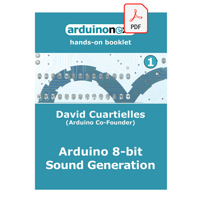
Arduinonext is an initiative powered by an electronics and microcontrollers specialist team aiming to help all those who are entering in the technology world, using the well-known Arduino platform to take the next step in electronics.
We strive to bring you the necessary knowledge and experience for developing your own electronics applications; interacting with environment; measuring physical parameters; processing them and performing the necessary control actions.
This is the first title in the 'Hands-On' series in which Arduino platform co-founder, David Cuartielles, introduces board programming, and demonstrates the making of an 8-bit Sound Generator.
The SDRplay RSP1B is an enhanced version of the popular RSP1A – a powerful, wideband, full-featured 14-bit SDR that covers the RF spectrum from 1 kHz to 2 GHz. The RSP1B comes in a rugged, black-painted steel case and offers significantly improved noise performance.
All it needs is a computer and an antenna to deliver excellent communications-receiver functionality. It includes a choice of SDRuno for Windows and the multi-platform SDRconnect software for Windows, macOS, and Linux (supplied free of charge by SDRplay). You can monitor up to 10 MHz of spectrum at a time.
A documented API allows developers to create new demodulators or applications for the platform.
Features
Covers all frequencies from 1 kHz through VLF, LF, MW, HF, VHF, UHF and L-band to 2 GHz, with no gaps
Receive, monitor and record up to 10 MHz of spectrum at a time
Free use of windows-based SDRuno software which provides an ever-increasing feature-set
Strong and growing software support network
Calibrated S meter/ RF power and SNR measurement with SDRuno (including datalogging to .CSV file capability)
Documented API provided to allow demodulator or application development on multiple platforms
Excellent dynamic range for challenging reception conditions
Works with popular 3rd party SDR software (including HDSDR, SDR Console and Cubic SDR)
ExtIO based plugin available
Software upgradeable for future standards
Strong and growing software support network
API provided to allow demodulator or application development
Multiplatform driver and API support including Windows, Linux, Mac, Android and Raspberry Pi
Up to 16 individual receivers in any 10 MHz slice of spectrum using SDRuno
Calibrated S meter and power measurements with SDRuno
Stand-alone windows-based spectrum analyser software available (with sweep, sample and hold features)
Ideal for monitoring of ISM/ IoT/ Telemetry bands <2 GHz
Ideal for portable operation
Specifications
Frequency Range
1 kHz – 2 GHz
Antenna Connector
SMA
Antenna Impedance
50 Ohms
Current Consumption (Typical)
185 mA (excl. Bias-T)
USB Connector
USB Type B
Maximum Input Power
+0 dBm Continuous+10 dBm Short Duration
ADC Sample Rates
2-10.66 MSPS
ADC Number of Bits
14 bit 2-6.048 MSPS12 bit 6.048-8.064 MSPS10 bit 8.064-9.216 MSPS8 bit >9.216 MSPS
Bias-T
4.7 V100 mA guaranteed
Reference
0.5ppm 24 MHz TCXO.Frequency error trimmable to 0.01ppm in field.
Operating Temperature Range
-10˚C to +60˚C
Dimensions
98 x 88 x 34 mm
Weight
110 g
Downloads
Datasheet
Software
RSP1B vs RSPdx vs RSPduo
RSP1B
RSPdx
RSPduo
Continuous coverage from 1 kHz to 2 GHz
✓
✓
✓
Up to 10 Mhz visible bandwidth
✓
✓
✓
14-bit ADC silicon technology plus multiple high-performance input filters
✓
✓
✓
Software selectable AM/FM & DAB broadcast band notch filters
✓
✓
✓
4.7 V Bias-T for powering external remote antenna amplifier
✓
✓
✓
Powers over the USB cable with a simple type B socket
✓
✓
✓
50Ω SMA antenna input(s) for 1 kHz to 2 GHz operation (software selectable)
1
2
2
Additional software selectable Hi-Z input for up to 30 Mhz operation
✓
Additional software selectable 50Ω BNC input for up to 200 MHz operation
✓
Additional LF/VLF filter for below 500 kHz
✓
24 MHz reference clock input (+ output on RSPduo)
✓
✓
Dual tuners enabling reception on 2 totally independent 2 MHz ranges
✓
Dual tuners enabling diversity reception using SDRuno
✓
Robust and strong plastic case (with internal RF shielding layer)
✓
Rugged black painted steel case
✓
✓
Overall performance below 2 MHz for MW and LF
+
++
+
Multiple simultaneous applications
+
+
++
Performance in challenging fading conditions (*using diversity tuning)
+
+
*++
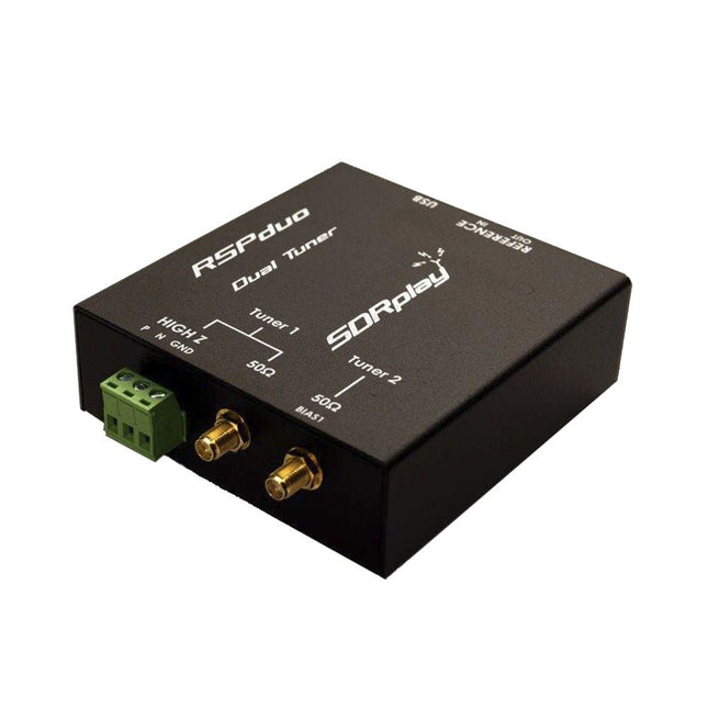
The SDRplay RSPduo is a high performance dual-tuner 14-bit SDR receiver. Housed in a high quality steel enclosure, each tuner can operate individually anywhere between 1 kHz and 2 GHz with up to 10 MHz of bandwidth or both tuners can operate simultaneously anywhere between 1 kHz and 2 GHz with up to 2 MHz of bandwidth per tuner.
A high stability reference along with external clocking features makes this device ideally suited to industrial, scientific & educational applications.
Features
Dual tuner provides independent coverage from 1 kHz to 2 GHz using 2 antenna ports simultaneously
14-bit ADC silicon technology
Up to 10 MHz visible bandwidth (single tuner mode) or 2 slices of 2 MHz spectrum (dual tuner mode)
3 software-selectable antenna ports (2x 50Ω and 1x 1kΩ high impedance balanced/unbalanced input)
High impedance antenna port (1 kHz to 30 MHz) with selectable MW notch filter and choice of 2 pre-selection filters
Software selectable AM/FM and DAB broadcast band notch filters for the 2 SMA antenna (1 kHz to 2 GHz) antenna ports
External clock input and output enables easy synchronisation to multiple RSPs or external reference clock
Powers over the USB cable with a simple type B socket
11 high-selectivity, built in front-end preselection filters on both the 2 SMA antenna ports
Software selectable multi-level Low Noise Preamplifier
Bias-T power supply for powering antenna-mounted LNA
Enclosed in a rugged black painted steel case.
SDRuno – World Class SDR software for Windows
Documented API for new apps development
Specifications
Frequency Range
1 kHz – 2 GHz
Antenna Connector
SMA
Antenna Impedance
50 Ohms
Current Consumption (Typical)
Single Tuner Mode: 180 mA (excl. Bias-T)Dual Tuner Mode: 280 mA (excl. Bias-T)
USB Connector
USB-B
Maximum Input Power
+0 dBm Continuous+10 dBm Short Duration
ADC Sample Rates
2-10.66 MSPS
ADC Number of Bits
14 bit 2-6.048 MSPS12 bit 6.048-8.064 MSPS10 bit 8.064-9.216 MSPS8 bit >9.216 MSPS
Bias-T
4.7 V100 mA guaranteed
Reference
High Temperature Stability (0.5ppm) 24 MHz TCXO.Frequency error trimmable to 0.01ppm in field.
Operating Temperature Range
−10˚C to +60˚C
Dimensions
98 x 94 x 33 mm
Weight
315 g
Downloads
Datasheet
Detailed Technical Information
Software
RSPdx-R2 vs RSPduo
RSPdx-R2
RSPduo
Continuous coverage from 1 kHz to 2 GHz
✓
✓
Up to 10 MHz visible bandwidth
✓
✓
14-bit ADC silicon technology plus multiple high-performance input filters
✓
✓
Software selectable AM/FM & DAB broadcast band notch filters
✓
✓
4.7 V Bias-T for powering external remote antenna amplifier
✓
✓
Powers over the USB cable with a simple type B socket
✓
✓
50Ω SMA antenna input(s) for 1 kHz to 2 GHz operation (software selectable)
2
2
Additional software selectable Hi-Z input for up to 30 Mhz operation
✓
Additional software selectable 50Ω BNC input for up to 200 MHz operation
✓
Additional LF/VLF filter for below 500 kHz
✓
24 MHz reference clock input (+ output on RSPduo)
✓
✓
Dual tuners enabling reception on 2 totally independent 2 MHz ranges
✓
Dual tuners enabling diversity reception using SDRuno
✓
Rugged black painted steel case
✓
✓
Overall performance below 2 MHz for MW and LF
++
+
Multiple simultaneous applications
+
++
Performance in challenging fading conditions (*using diversity tuning)
+
*++
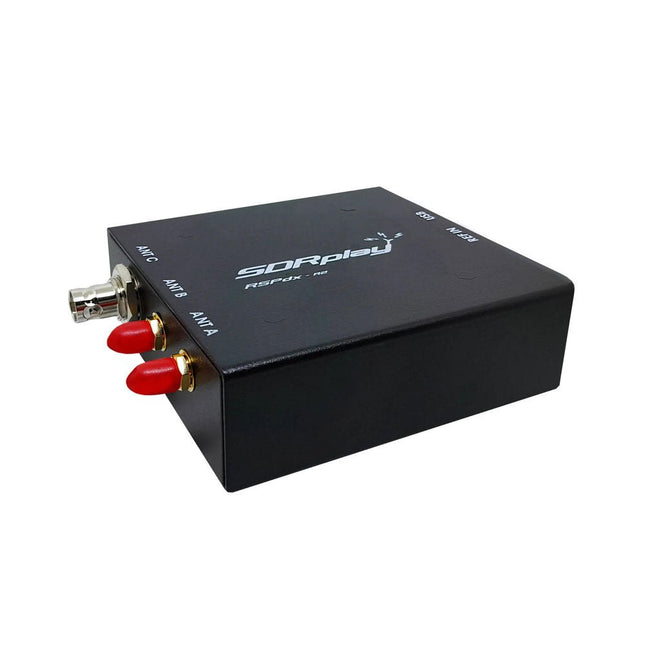
The SDRplay RSPdx-R2 is a wideband full featured single-tuner 14-bit SDR receiver which covers the entire RF spectrum from 1 kHz to 2 GHz giving up to 10 MHz of spectrum visibility. It contains three antenna ports, two of which use SMA connectors and operate across the full 1 kHz to 2 GHz range and the third uses a BNC connector which operates up to 200 MHz.
The RSPdx-R2 is an enhanced version of the RSPdx with further design improvements for use at frequencies below 2 MHz. Housed in a strong steel case, in addition to the functionality of the RSP1B, the RSPdx-R2 provides three software selectable antenna inputs and an external clock input. It offers excellent performance through HF and VHF frequencies all the way up to 2 GHz. The RSPdx-R2 also supports an "HDR mode" optimised for the demanding radio reception conditions below 2 MHz.
The RSPdx-R2, when used in conjunction with SDRplay’s own software, introduces a special HDR (High Dynamic Range) mode for reception within selected bands below 2 MHz. HDR mode delivers improved intermodulation performance and fewer spurious responses for those challenging bands.
Features
Covers all frequencies from 1 kHz through VLF, LF, MW, HF, VHF, UHF and L-band to 2 GHz, with no gaps
Receive, monitor and record up to 10 MHz of spectrum at a time
Significantly improved noise performance below 1 MHz (i.e. for some MF, LF and below)
Improved dynamic range below 2 MHz both in tuner mode and HDR mode
HDR mode below 2 MHz giving overall dynamic range and selectivity advantages
Software selectable choice of 3 antenna ports
External clock input for synchronisation purposes, or connection to GPS reference clock for extra frequency accuracy
Excellent dynamic range for challenging reception conditions
Free use of Windows-based SDRuno software (check website for versions supported)
Free use of SDRconnect SDR and server software for Windows, MacOS and Linux (Check website for versions supported)
Multiplatform driver and API support including Windows, Linux, Mac and Raspberry Pi 4/5
Strong and growing software support network
Calibrated S meter/RF power and SNR measurement with SDRuno (including datalogging to .CSV file capability)
Documented API provided to allow demodulator or application development on multiple platforms
Applications (Amateur)
Shortwave radio listening
Broadcast DXing (AM/FM/TV)
Panadaptor
Aircraft (ADS-B and ATC)
Slow Scan TV
Multi-amateur band monitoring
WSPR & digital modes
Weather fax (HF and satellite)
Satellite monitoring
Geostationary environmental satellites
Trunked radio
Utility and emergency service monitoring
Fast and effective antenna comparison
Applications (Industrial)
Spectrum Analyser
Surveillance
Wireless microphone monitoring
RF surveying
IoT receiver chain
Signal logging
RFI/EMC detection
Broadcast integrity monitoring
Spectrum monitoring
Power measurement
Applications (Educational/Scientific)
Teaching
Receiver design
Radio astronomy
Passive radar
Ionosonde
Spectrum analyser
Receiver for IoT sensor projects
Antenna research
Specifications
Frequency Range
1 kHz – 2 GHz
Antenna Connector
SMA
Antenna Impedance
50 Ohms
Current Consumption (Typical)
190 mA @ >60 MHz (excl. Bias-T)120 mA @ <60 MHz (excl. Bias-T)
USB Connector
USB-B
Maximum Input Power
+0 dBm Continuous+10 dBm Short Duration
ADC Sample Rates
2-10.66 MSPS
ADC Number of Bits
14 bit 2-6.048 MSPS12 bit 6.048-8.064 MSPS10 bit 8.064-9.216 MSPS8 bit >9.216 MSPS
Bias-T
4.7 V100 mA guaranteed
Reference
0.5ppm 24 MHz TCXOFrequency error trimmable to 0.01ppm in field
Operating Temperature
−10˚C to +60˚C
Dimensions
113 x 94 x 35 mm
Weight
315 g
Downloads
Datasheet
Software
RSPdx-R2 vs RSPduo
RSPdx-R2
RSPduo
Continuous coverage from 1 kHz to 2 GHz
✓
✓
Up to 10 MHz visible bandwidth
✓
✓
14-bit ADC silicon technology plus multiple high-performance input filters
✓
✓
Software selectable AM/FM & DAB broadcast band notch filters
✓
✓
4.7 V Bias-T for powering external remote antenna amplifier
✓
✓
Powers over the USB cable with a simple type B socket
✓
✓
50Ω SMA antenna input(s) for 1 kHz to 2 GHz operation (software selectable)
2
2
Additional software selectable Hi-Z input for up to 30 Mhz operation
✓
Additional software selectable 50Ω BNC input for up to 200 MHz operation
✓
Additional LF/VLF filter for below 500 kHz
✓
24 MHz reference clock input (+ output on RSPduo)
✓
✓
Dual tuners enabling reception on 2 totally independent 2 MHz ranges
✓
Dual tuners enabling diversity reception using SDRuno
✓
Rugged black painted steel case
✓
✓
Overall performance below 2 MHz for MW and LF
++
+
Multiple simultaneous applications
+
++
Performance in challenging fading conditions (*using diversity tuning)
+
*++
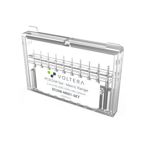
A set of high precision drill bits, covering the most common drill bit sizes.
Just pop them in the V-One Drill with a 2.5 mm hex key (not included) and start drilling.
The following sizes are included (2 of each):
0.70 mm
0.80 mm
0.90 mm
1.00 mm
1.60 mm
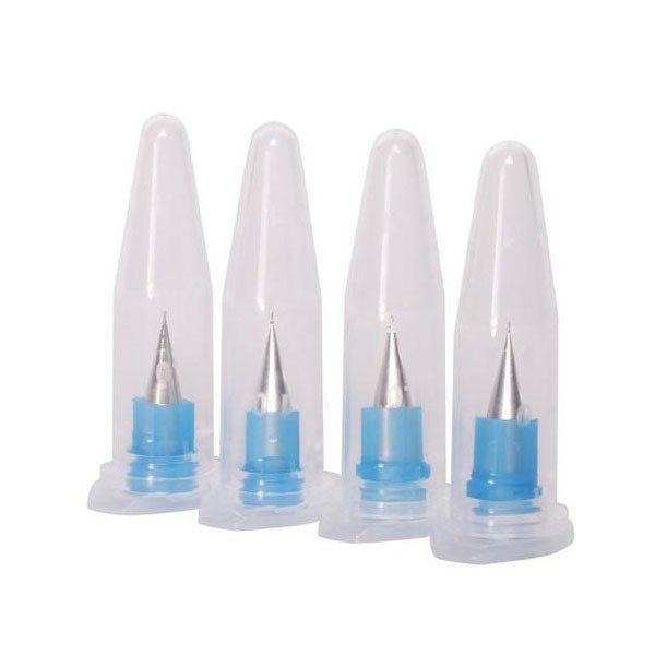
If you want to push the resolution limits of the V-One, these dispensing tips will help enable your experimental projects. This pack contains 4 extra fine nozzles with an internal diameter of 0.150 mm (6 mil).
Do not use with solder paste! It will clog!
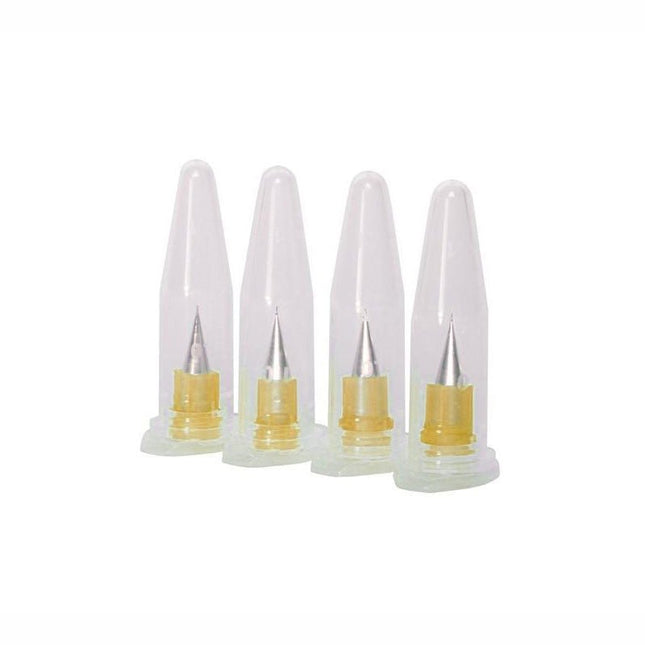
Looking to dispense materials with a lower viscosity? These are the nozzles for you. Don't use this with our standard ink or solder paste... that will result in poor performance.
This pack contains 4 extra fine nozzles with an internal diameter of 0.100 mm (4 mil).
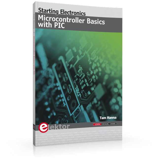
In this book the author presents all essential aspects of microcontroller programming, without overloading the reader with unnecessary or quasi-relevant bits of information. Having read the book, you should be able to understand as well as program, 8-bit microcontrollers.
The introduction to microcontroller programming is worked out using microcontrollers from the PIC series. Not exactly state-of-the-art with just 8 bits, the PIC micro has the advantage of being easy to comprehend. It is offered in a DIP enclosure, widely available and not overly complex. The entire datasheet of the PIC micro is shorter by decades than the description of the architecture outlining the processor section of an advanced microcontroller. Simplicity has its advantages here. Having mastered the fundamental operation of a microcontroller, you can easily enter into the realms of advanced softcores later.
Having placed assembly code as the executive programming language in the foreground in the first part of the book, the author reaches a deeper level with ‘C’ in the second part. Cheerfully alongside the official subject matter, the book presents tips & tricks, interesting measurement technology, practical aspects of microcontroller programming, as well as hands-on options for easier working, debugging and faultfinding.