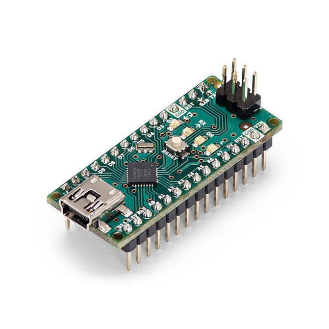
The Arduino Nano is a small, complete, and breadboard-friendly board based on the ATmega328 (Arduino Nano 3.x). It has more or less the same functionality of the Arduino Duemilanove but in a different package. It lacks only a DC power jack and works with a Mini-B USB cable instead of a standard one.
Specifications
Microcontroller
ATmega328
Operating Voltage (logic level)
5 V
Input Voltage (recommended)
7-12 V
Input Voltage (limits)
6-20 V
Digital I/O Pins
14 (of which 6 provide PWM output)
Analog Input Pins
8
DC Current per I/O Pin
40 mA
Flash Memory
16 KB (ATmega168) or 32 KB (ATmega328) of which 2 KB used by bootloader
SRAM
1 KB (ATmega168) or 2 KB (ATmega328)
EEPROM
512 bytes (ATmega168) or 1 KB (ATmega328)
Clock Speed
16 MHz
Dimensions
0.73 x 1.70' (18 x 45 mm)
Power
The Arduino Nano can be powered via the Mini-B USB connection, 6-20 V unregulated external power supply (pin 30), or 5 V regulated external power supply (pin 27). The power source is automatically selected to the highest voltage source.
Memory
The ATmega168 has 16 KB of flash memory for storing code (of which 2 KB is used for the bootloader), 1 KB of SRAM and 512 bytes of EEPROM
The ATmega328 has 32 KB of flash memory for storing code, (also with 2 KB used for the bootloader), 2 KB of SRAM and 1 KB of EEPROM.
Input and Output
Each of the 14 digital pins on the Nano can be used as an input or output, using pinMode(), digitalWrite(), and digitalRead() functions. They operate at 5 V.
Each pin can provide or receive a maximum of 40 mA and has an internal pull-up resistor (disconnected by default) of 20-50 kOhms.
Communication
The Arduino Nano has a number of facilities for communicating with a computer, another Arduino, or other microcontrollers.
The ATmega168 and ATmega328 provide UART TTL (5V) serial communication, which is available on digital pins 0 (RX) and 1 (TX). An FTDI FT232RL on the board channels this serial communication over USB and the FTDI drivers (included with the Arduino software) provide a virtual com port to software on the computer.
The Arduino software includes a serial monitor which allows simple textual data to be sent to and from the Arduino board. The RX and TX LEDs on the board will flash when data is being transmitted via the FTDI chip and USB connection to the computer (but not for serial communication on pins 0 and 1).
A SoftwareSerial library allows for serial communication on any of the Nano's digital pins.
Programming
The Arduino Nano can be programmed with the Arduino software (download).
The ATmega168 or ATmega328 on the Arduino Nano comes with a bootloader that allows you to upload new code to it without the use of an external hardware programmer. It communicates using the original STK500 protocol (reference, C header files).
You can also bypass the bootloader and program the microcontroller through the ICSP (In-Circuit Serial Programming) header using Arduino ISP or similar; see these instructions for details.
Automatic (Software) Reset
Rather than requiring a physical press of the reset button before an upload, the Arduino Nano is designed in a way that allows it to be reset by software running on a connected computer.
One of the hardware flow control lines (DTR) of theFT232RL is connected to the reset line of the ATmega168 or ATmega328 via a 100 nF capacitor. When this line is asserted (taken low), the reset line drops long enough to reset the chip.
The Arduino software uses this capability to allow you to upload code by simply pressing the upload button in the Arduino environment. This means that the bootloader can have a shorter timeout, as the lowering of DTR can be well-coordinated with the start of the upload.
The JOY-iT Armor Case BLOCK is a robust aluminum enclosure designed specifically for the Raspberry Pi 5. It offers excellent protection against heat and physical shocks, making it suitable for challenging environments. Its compact design ensures that it doesn't require additional space, allowing for seamless integration into existing projects.
The case includes a large heatsink to enhance cooling efficiency. Installation is straightforward, with four screws (included) securing the case to the Raspberry Pi.
Specifications
Material
CNC milled aluminum alloy
Cooling performance
Idle: ~39°CFull load: ~75°C
Special features
Large heat sink, protection against shocks and heat with the same volume as without housing
Dimensions (top side)
69 x 56 x 15,5 mm
Dimensions (bottom side)
87 x 56 x 7,5 mm
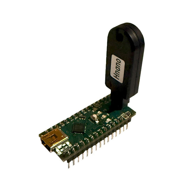
This programmer is specifically designed for burning bootloaders (without a computer) on Arduino-compatible ATmega328 development boards.
Simply plug the programmer into the ICSP interface to re-burn the bootloader. It’s also compatible with new chips, provided the IC is functional.
Note: Burning a bootloader erases all previous chip data.
Features
Working voltage: 3.1-5.3 V
Working current: 10 mA
Compatible with Arduino Nano based boards (ATmega328)
Dimensions: 39.6 x 15.5 x 7.8 mm
The Elektor Arduino Nano MCCAB Training Board contains all the components (incl. Arduino Nano) required for the exercises in the "Microcontrollers Hands-on Course for Arduino Starters", such as light-emitting diodes, switches, pushbuttons, acoustic signal transmitters, etc. External sensors, motors or assemblies can also be queried or controlled with this microcontroller training system.
Specifications (Arduino Nano MCCAB Training Board)
Power Supply
Via the USB connection of the connected PC or an external power supply unit (not included)
Operating Voltage
+5 Vcc
Input Voltage
All inputs
0 V to +5 V
VX1 and VX2
+8 V to +12 V (only when using an external power supply)
Hardware periphery
LCD
2x16 characters
Potentiometer P1 & P2
JP3: selection of operating voltage of P1 & P2
Distributor
SV4: Distributor for the operating voltagesSV5, SV6: Distributor for the inputs/outputs of the microcontroller
Switches and buttons
RESET button on the Arduino Nano module 6x pushbutton switches K1 ... K6 6x slide switches S1 ... S6 JP2: Connection of the switches with the inputs of the microcontroller
Buzzer
Piezo buzzer Buzzer1 with jumper on JP6
Indicator lights
11 x LED: Status indicator for the inputs/outputs LED L on the Arduino Nano module, connected to GPIO D13 JP6: Connection of LEDs LD10 ... LD20 with GPIOs D2 ... D12
Serial interfacesSPI & I²C
JP4: Selection of the signal at pin X of the SPI connector SV12 SV9 to SV12: SPI interface (3.3 V/5 V) or I²C interface
Switching output for external devices
SV1, SV7: Switching output (maximum +24 V/160 mA, externally supplied) SV2: 2x13 pins for connection of external modules
3x3 LED matrix(9 red LEDs)
SV3: Columns of the 3x3 LED matrix (outputs D6 ... D8) JP1: Connection of the rows with the GPIOs D3 ... D5
Software
Library MCCABLib
Control of hardware components (switches, buttons, LEDs, 3x3 LED matrix, buzzer) on the MCCAB Training Board
Operating Temperature
Up to +40 °C
Dimensions
100 x 100 x 20 mm
Specifications (Arduino Nano)
Microcontroller
ATmega328P
Architecture
AVR
Operating Voltage
5 V
Flash Memory
32 KB, of which 2 KB used by bootloader
SRAM
2 KB
Clock Speed
16 MHz
Analog IN Pins
8
EEPROM
1 KB
DC Current per I/O Pins
40 mA on one I/O pin, total maximum 200 mA on all pins together
Input Voltage
7-12 V
Digital I/O Pins
22 (6 of which are PWM)
PWM Output
6
Power Consumption
19 mA
Dimensions
18 x 45 mm
Weight
7 g
Included
1x Elektor Arduino Nano Training Board MCCAB
1x Arduino Nano
Get Cracking with the Arduino Nano V3, Nano Every, and Nano 33 IoT
The seven chapters in this book serve as the first step for novices and microcontroller enthusiasts wishing to make a head start in Arduino programming. The first chapter introduces the Arduino platform, ecosystem, and existing varieties of Arduino Nano boards. It also teaches how to install various tools needed to get started with Arduino Programming. The second chapter kicks off with electronic circuit building and programming around your Arduino. The third chapter explores various buses and analog inputs. In the fourth chapter, you get acquainted with the concept of pulse width modulation (PWM) and working with unipolar stepper motors.
In the fifth chapter, you are sure to learn about creating beautiful graphics and basic but useful animation with the aid of an external display. The sixth chapter introduces the readers to the concept of I/O devices such as sensors and the piezo buzzer, exploring their methods of interfacing and programming with the Arduino Nano. The last chapter explores another member of Arduino Nano family, Arduino Nano 33 IoT with its highly interesting capabilities. This chapter employs and deepens many concepts learned from previous chapters to create interesting applications for the vast world of the Internet of Things.
The entire book follows a step-by-step approach to explain concepts and the operation of things. Each concept is invariably followed by a to-the-point circuit diagram and code examples. Next come detailed explanations of the syntax and the logic used. By closely following the concepts, you will become comfortable with circuit building, Arduino programming, the workings of the code examples, and the circuit diagrams presented. The book also has plenty of references to external resources wherever needed.
An archive file (.zip) comprising the software examples and Fritzing-style circuit diagrams discussed in the book may be downloaded free of charge below.
The starter kit for Jetson Nano is one of the best kits for beginners to get started with Jetson Nano. This kit includes 32 GB MicroSD card, 20 W adapter, 2-pin jumper, camera, and micro-USB cable.
Features
32 GB High-performance MicroSD card
5 V 4 A power supply with 2.1 mm DC barrel connector
2-pin jumper
Raspberry Pi camera module V2
Micro-B To Type-A USB cable with DATA enabled
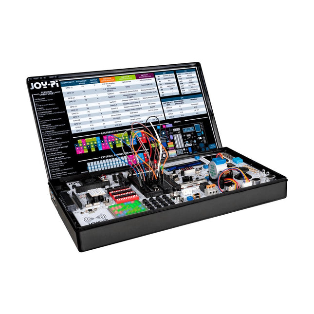
The Joy-Pi Advanced is a compact and powerful device that allows you to realize your projects quickly and easily. Whether you already have a lot of experience, or next to none, the Joy-Pi Advanced lets you unleash your creativity. Thanks to its compatibility with a wide range of platforms, including Raspberry Pi, Raspberry Pi Pico, Arduino Nano, BBC micro:bit, and NodeMCU ESP32, you can easily and quickly access your preferred platform.
In addition, the Joy-Pi Advanced features more than 30 stations, lessons, and modules, giving you an unlimited variety of ways to get your projects done. With the self-developed learning center, you can not only improve your skills but also create new projects. The learning center offers a wealth of information and tutorials that will guide you step by step through your projects.
Joy-Pi Advanced is characterized in particular by its intelligent switch units, which allow an extended use of the available pins. A total of three switch units are integrated, each equipped with 12 individual switches that provide precise control of the connected sensors and modules. This system solves the well-known problem of limited pin count that occurs with conventional microcontrollers. The switch units allow you to operate a large number of sensors and modules in parallel by switching them on and off individually. This simulates multiple pin assignment, allowing you to exploit the full power of your projects without compromising functionality.
By combining innovative adapter boards and the micro:bit slot, you can achieve seamless compatibility with a wide range of microcontrollers such as Raspberry Pi Pico, NodeMCU ESP32, micro:mit and Arduino Nano. The specially developed adapter boards are designed to perfectly match the respective microcontroller. By plugging the microcontroller onto the appropriate adapter board and then plugging it into the micro:bit slot, the Joy-Pi Advanced quickly and easily becomes compatible with the different microcontrollers. This allows seamless integration of your preferred platform and the ability to combine the strengths of the different microcontrollers in your projects. This way, you can fully focus on your creative projects without worrying about the compatibility of different microcontrollers. The Joy-Pi Advanced simplifies the development process and gives you the possibility to design your projects flexibly and individually.
Features
Highly integrated development platform & learning center
Fast, easy & wireless combination of various sensors & actuators
Installation option for Raspberry Pi 4
Compatible with various microcontrollers
Self-developed, didactic learning platform for Raspberry Pi & Windows
Specifications
Compatible to
Raspberry Pi 4, Arduino Nano, NodeMCU ESP32, BBC micro:bit, Raspberry Pi Pico
Installed sensors, actuators & components
39
Learning platform
Over 40 entries in the know-ledge database, 10 projects, 10 learning tasks, 14 visions
Displays
7-segment display, 16x2 display, 1.8“ TFT display, 0.96" OLED display, 8x8 RGB matrix
Sensors
DS18B20, shock sensor, hall sensor, barometer, sound sensor, gyroscope, PIR sensor, Light barrier, NTC, Light sensor, 6x touch sensor, color sensor, ultrasonic distance sensor, DHT11 temperature & humidity sensor
Control
Joystick, 5x switches, potentiometer, rotary encoder, 4x4 button matrix, relays, PWM fan
Motors
Servo interface, Stepper motor interface, Vibration motor
Measuring & conversion modules
Analog-Digital Converter, Level converter, voltmeter, Variable voltage supply
Other components
RTC real time clock, buzzer, EEPROM memory, infrared receiver, breadboard, RFID reader
Adapter boards
Adapter for NodeMCU ESP32, Arduino Nano & Raspberry Pi Pico, Board connectors for Raspberry Pi & External Boards
Electronic components
Infrared remote control, RFID chip, RFID card, 6x alligator clips, microSD card reader, servo motor, stepper motor, 32 GB microSD card
Components
40x resistors, 3x green LEDs, 3x yellow LEDs, 3x red LEDs, 1x transistor, 5x buttons, 1x potentiometer, 2x capacitors
Other accessories
Screw assortment, screwdriver, accessory storage bag, power supply & power cable, servo mount
Power supply
Built-in power supply: 36 W, 12 V, 3 A Case connector: Small device plug C8
Voltage outputs
12 V, 5 V, 3.3 V, Variable voltage output (2-11 V)
Data buses & signal outputs
I²C, SPI, Analog to digital converter
Battery (RTC)
CR2032
Dimensions
327 x 200 x 52 mm
Required
Raspberry Pi 4 with at least 2 GB RAM
Downloads
Joy-Pi website
Datasheet
Manual
The reComputer J1020 v2 is a compact edge AI device powered by the NVIDIA Jetson Nano 4 GB production module, delivering 0.5 TFLOPs of AI performance. It features a robust aluminum case with a passive heatsink and comes pre-installed with JetPack 4.6.1. The device includes 16 GB of onboard eMMC storage and offers 2x SCI, 4x USB 3.0, M.2 Key M, HDMI, and DP.
Applications
Computer Vision
Machine Learning
Autonomous Mobile Robot (AMR)
Specifications
Jetson Nano 4 GB System-on-Module
AI Performance
Jetson Nano 4 GB (0.5 TOPS)
GPU
NVIDIA Maxwel architecture with 128 NVIDIA CUDA cores
CPU
Quad-core ARM Cortex-A57 MPCore processor
Memory
4 GB 64-bit LPDDR4 25.6 GB/s
Video Encoder
1x 4K30 | 2x 1080p60 | 4x 1080p30 | 4x 720p60 | 9x 720p30 (H.265 & H.264)
Video Decoder
1x 4K60 | 2x 4K30 | 4x 1080p60 | 8x 1080p30 | 9x 720p60 (H.265 & H.264)
Carrier Board
Storage
1x M.2 Key M PCIe
Networking
Ethernet
1x RJ-45 Gigabit Ethernet (10/100/1000M)
I/O
USB
4x USB 3.0 Type-A1x Micro-USB port for device mode
CSI Camera
2x CSI (2-lane 15-pin)
Display
1x HDMI Type A; 1x DP
Fan
1x 4-pin Fan Connector (5 V PWM)
CAN
1x CAN
Multifunctional Port
1x 40-Pin Expansion header
1x 12-Pin Control and UART header
Power Supply
DC 12 V/2 A
Mechanical
Dimensions
130 x 120 x 50 mm (with Case)
Installation
Desktop, wall-mounting
Operating Temperature
−10°C~60°C
Included
reComputer J1020 v2 (system installed)
12 V/2 A power adapter (with 5 interchangeable adapter plugs)
Downloads
reComputer J1020 v2 datasheet
reComputer J1020 v2 3D file
Seeed NVIDIA Jetson Product Catalog
NVIDIA Jetson Device and Carrier Boards Comparison
An Introduction to Real and Reduced-Scale Autonomous Vehicles
Want to cut through the hype and get to the core of autonomous and connected vehicles? Then this book is your clear, accessible guide to a complex and fast-moving field. Starting with Intelligent Transport Systems (ITS), it walks you through the essential foundations, including Advanced Driver Assistance Systems (ADAS) – the stepping stones to full autonomy.
Explore how self-driving cars mimic human behavior through a loop of perception, analysis, decision, and action. Discover the key functions that make it possible: localization, obstacle detection, driver monitoring, cooperative awareness – and the most challenging of all, trajectory planning, across strategic, tactical, and operational levels.
Will vehicles be connected? The debate is on – but the standards are already here. Learn how connectivity, infrastructure, and vehicles can work in synergy through the innovative concept of floating car data (FCD).
Dive into real-world implementation: with embedded electronics account-ing for over 30% of a modern vehicle‘s cost, we unpack the architecture, coordination, and tools required to manage the complexity – brought to life with a hands-on case study.
To finish, we open the door to the future: building your own 1:10 scale autonomous vehicle. No plug-and-play solutions – just the foundations for a collaborative, creative, and geek-friendly challenge.
Let’s drive the future together.
,
by Clemens Valens
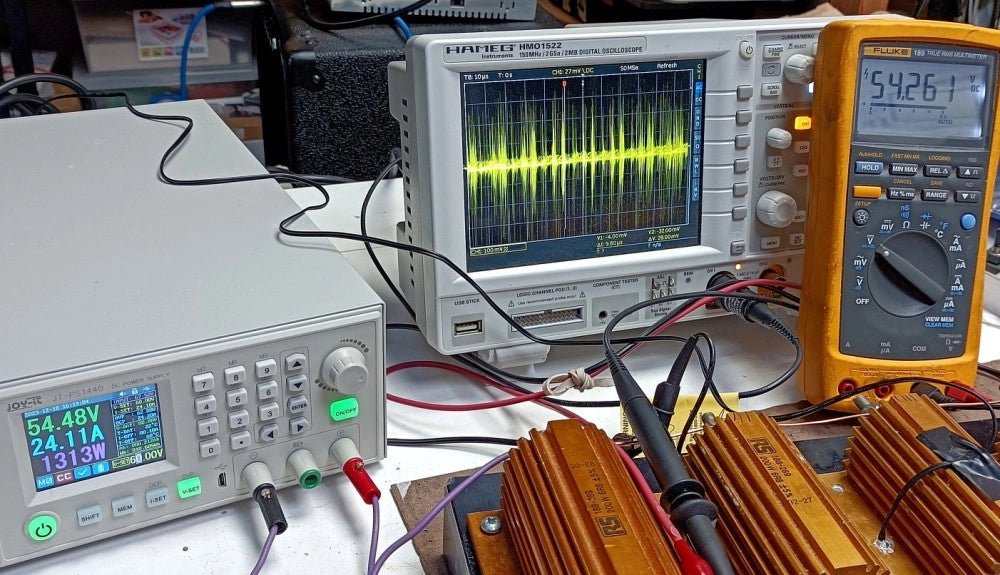
Trying Out the Joy-it JT-PS1440-C 1.5 kW Power Supply (Review)
In today's high-powered world of e-bikes, electric scooters, and various other electronic vehicles, robust and adaptable power supplies are indispensable for motor testing and battery...