Search results for "adafruit OR neopixel OR digital OR rgb OR led OR strip OR white OR 60 OR led OR 4 OR m"
-
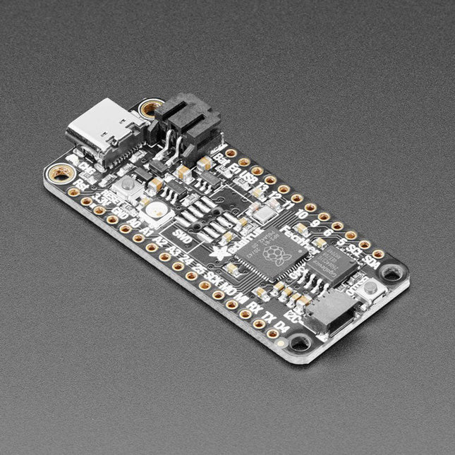
Adafruit Adafruit Feather RP2040
Inside the RP2040 is a 'permanent ROM' USB UF2 bootloader. What that means is when you want to program new firmware, you can hold down the BOOTSEL button while plugging it into USB (or pulling down the RUN/Reset pin to ground) and it will appear as a USB disk drive you can drag the firmware onto. Folks who have been using Adafruit products will find this very familiar – Adafruit uses the technique on all thier native-USB boards. Just note you don't double-click reset, instead hold down BOOTSEL during boot to enter the bootloader!The RP2040 is a powerful chip, which has the clock speed of our M4 (SAMD51), and two cores that are equivalent to our M0 (SAMD21). Since it is an M0 chip, it does not have a floating point unit, or DSP hardware support – so if you're doing something with heavy floating-point math, it will be done in software and thus not as fast as an M4. For many other computational tasks, you'll get close-to-M4 speeds!For peripherals, there are two I²C controllers, two SPI controllers, and two UARTs that are multiplexed across the GPIO – check the pinout for what pins can be set to which. There are 16 PWM channels, each pin has a channel it can be set to (ditto on the pinout).Technical Specifications Measures 2.0 x 0.9 x 0.28' (50.8 x 22.8 x 7 mm) without headers soldered in Light as a (large?) feather – 5 grams RP2040 32-bit Cortex M0+ dual core running at ~125 MHz @ 3.3 V logic and power 264 KB RAM 8 MB SPI FLASH chip for storing files and CircuitPython/MicroPython code storage. No EEPROM Tons of GPIO! 21 x GPIO pins with following capabilities: Four 12 bit ADCs (one more than Pico) Two I²C, Two SPI and two UART peripherals, one is labeled for the 'main' interface in standard Feather locations 16 x PWM outputs - for servos, LEDs, etc The 8 digital 'non-ADC/non-peripheral' GPIO are consecutive for maximum PIO compatibility Built in 200 mA+ lipoly charger with charging status indicator LED Pin #13 red LED for general purpose blinking RGB NeoPixel for full color indication. On-board STEMMA QT connector that lets you quickly connect any Qwiic, STEMMA QT or Grove I²C devices with no soldering! Both Reset button and Bootloader select button for quick restarts (no unplugging-replugging to relaunch code) 3.3 V Power/enable pin Optional SWD debug port can be soldered in for debug access 4 mounting holes 24 MHz crystal for perfect timing. 3.3 V regulator with 500mA peak current output USB Type C connector lets you access built-in ROM USB bootloader and serial port debugging RP2040 Chip Features Dual ARM Cortex-M0+ @ 133 MHz 264 kB on-chip SRAM in six independent banks Support for up to 16 MB of off-chip Flash memory via dedicated QSPI bus DMA controller Fully-connected AHB crossbar Interpolator and integer divider peripherals On-chip programmable LDO to generate core voltage 2 on-chip PLLs to generate USB and core clocks 30 GPIO pins, 4 of which can be used as analog inputs Peripherals 2 UARTs 2 SPI controllers 2 I²C controllers 16 PWM channels USB 1.1 controller and PHY, with host and device support 8 PIO state machines Comes fully assembled and tested, with the UF2 USB bootloader. Adafruit also tosses in some header, so you can solder it in and plug it into a solderless breadboard.
€ 16,95
Members € 15,26
-
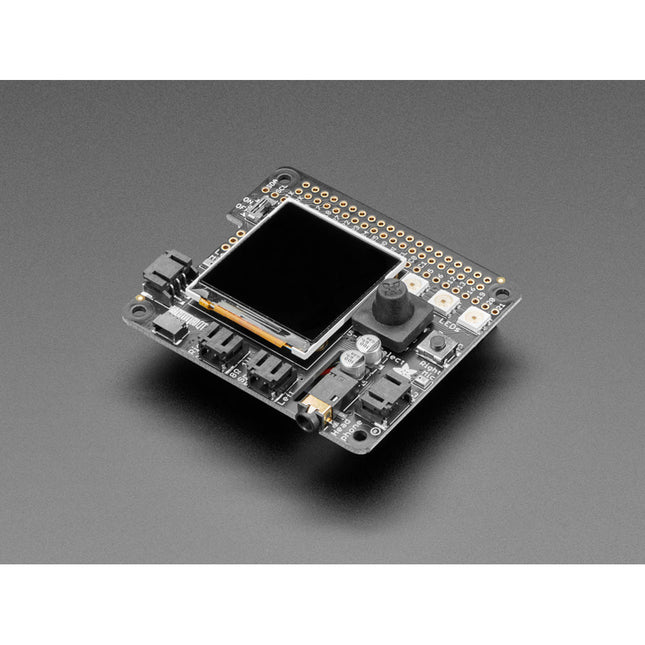
Adafruit Adafruit BrainCraft HAT – Machine Learning for Raspberry Pi 4
Features 1.54" IPS TFT display with 240x240 resolution that can show text or video Stereo speaker ports for audio playback - either text-to-speech, alerts or for creating a voice assistant. Stereo headphone out for audio playback through a stereo system, headphones, or powered speakers. Stereo microphone input - perfect for making your very own smart home assistants Two 3-pin JST STEMMA connectors that can be used to connect more buttons, a relay, or even some NeoPixels! STEMMA QT plug-and-play I2C port can be used with any of Adafruits 50+ I2C STEMMA QT boards or can be used to connect to Grove I²C devices with an adapter cable. 5-Way Joystick + Button for user interface and control. Three RGB DotStar LEDs for colorful LED feedback. The STEMMA QT port means you can attach heat image sensors like the Panasonic Grid-EYE or MLX90640. Heat-Sensitive cameras can be used as a person detector, even in the dark! An external accelerometer can be attached for gesture or vibration sensing such as machinery/industrial predictive maintenance projects Please note: A Raspberry Pi 4 is not included.
€ 49,95€ 34,95
Members identical
-
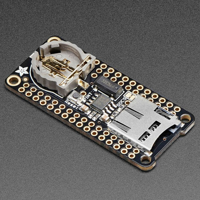
Adafruit Adafruit Adalogger FeatherWing (RTC + SD Add-on)
This FeatherWing will make it easy to add data logging to any Feather Board you might have. You get both an I²C real-time clock (PCF8523) with 32 KHz crystal and battery backup, and a microSD socket that connects to the SPI port pins (+ extra pin for CS). Note: FeatherWing doesn't come with a microSD card. A CR1220 coin cell is required to use the RTC battery-backup capabilities. If you're not using the RTC part of the FeatherWing, a battery is not required. To talk to the microSD card socket Arduino's default SD library is recommended. Some light soldering is required to attach the headers onto the Wing. Pinouts Power pins On the bottom row, the 3.3 V (second from left) and GND (fourth from left) pin are used to power the SD card and RTC (to take a load off the coin cell battery when main power is available) RTC & I²C Pins In the top right, SDA (rightmost) and SCL (to the left of SDA) are used to talk to the RTC chip. SCL - I²C clock pin to connect to your microcontroller's I2C clock line. This pin has a 10 kΩ pull-up resistor to 3.3 V SDA - I²C data pin to connect to your microcontroller's I2C data line. This pin has a 10 kΩ pull-up resistor to 3.3 V There's also a breakout for INT which is the output pin from the RTC. It can be used as an interrupt output or it could also be used to generate a square wave. Note that this pin is an open drain - you must enable the internal pull-up on whatever digital pin it is connected to. SD & SPI Pins Starting from the left you've got SPI Clock (SCK) - output from feather to wing SPI Master Out Slave In (MOSI) - output from feather to wing SPI Master In Slave Out (MISO) - input from wing to feather These pins are in the same location on every Feather. They are used for communicating with the SD card. When the SD card is not inserted, these pins are completely free. MISO is tri-stated whenever the SD CS (chip select) pin is pulled high
€ 10,95
Members € 9,86
-
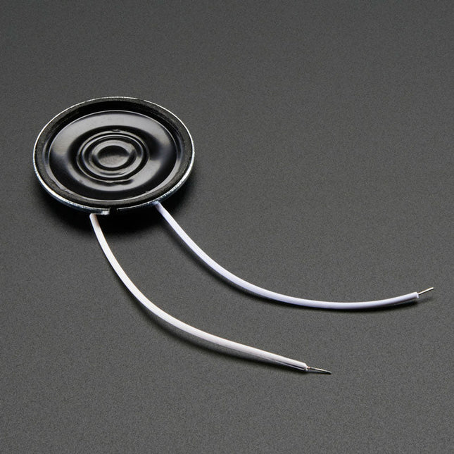
Adafruit Adafruit Mini Metal Speaker with Wires (8 ohm, 0.5 W)
Specifications Datasheet Resonance Frequency (FO): 680 ±20% Hz at 1 V Rated Impedance: 8 ±20% Ω (at 1 KHz) Frequency Range: ~600-10 KHz Rated Input Power: 0.25 W Max Input Power: 0.5 W Temperature Range: -20ºC ~ 55ºC Dimensions Diameter: 28 mm / 1.1' Height: 4.5 mm Weight: 6 g
€ 3,95
Members € 3,56
-
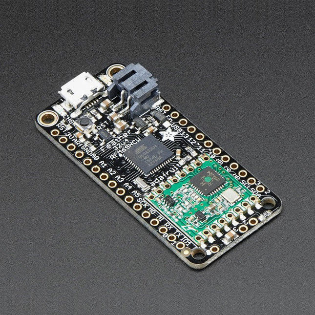
Adafruit Adafruit Feather 32u4 RFM69HCW Packet Radio (868 or 915 MHz) RadioFruit
This 900 MHz radio version can be used for either 868 MHz or 915 MHz transmission/reception – the exact radio frequency is determined when you load the software since it can be tuned around dynamically. At the Feather 32u4's heart is at ATmega32u4 clocked at 8 MHz and at 3.3 V logic. This chip has 32 K of flash and 2 K of RAM, with built in USB so not only does it have a USB-to-Serial program & debug capability built in with no need for an FTDI-like chip, it can also act like a mouse, keyboard, USB MIDI device, etc. To make it easy to use for portable projects, we added a connector for any 3.7 V Lithium polymer batteries and built in battery charging. You don't need a battery, it will run just fine straight from the micro USB connector. But, if you do have a battery, you can take it on the go, then plug in the USB to recharge. The Feather will automatically switch over to USB power when its available. We also tied the battery thru a divider to an analog pin, so you can measure and monitor the battery voltage to detect when you need a recharge. Features Measures 2.0' x 0.9' x 0.28' (51 x 23 x 8 mm) without headers soldered in Light as a (large?) feather – 5.5 grams ATmega32u4 @ 8 MHz with 3.3 V logic/power 3.3 V regulator with 500 mA peak current output USB native support, comes with USB bootloader and serial port debugging You also get tons of pins – 20 GPIO pins Hardware Serial, hardware I²C, hardware SPI support 7x PWM pins 10x analog inputs Built in 100 mA lipoly charger with charging status indicator LED Pin #13 red LED for general purpose blinking Power/enable pin 4 mounting holes Reset button The Feather 32u4 Radio uses the extra space left over to add an RFM69HCW 868/915 MHz radio module. These radios are not good for transmitting audio or video, but they do work quite well for small data packet transmission when you ned more range than 2.4 GHz (BT, BLE, WiFi, ZigBee) SX1231 based module with SPI interface Packet radio with ready-to-go Arduino libraries Uses the license-free ISM band ('European ISM' @ 868 MHz or 'American ISM' @ 915 MHz) +13 to +20 dBm up to 100 mW Power Output Capability (power output selectable in software) 50 mA (+13 dBm) to 150 mA (+20 dBm) current draw for transmissions Range of approx. 350 meters, depending on obstructions, frequency, antenna and power output Create multipoint networks with individual node addresses Encrypted packet engine with AES-128 Simple wire antenna or spot for uFL connector Comes fully assembled and tested, with a USB bootloader that lets you quickly use it with the Arduino IDE. Headrs are also included so you can solder it in and plug into a solderless breadboard. You will need to cut and solder on a small piece of wire (any solid or stranded core is fine) in order to create your antenna. Lipoly battery and USB cable not included.
€ 34,95
Members € 31,46
-
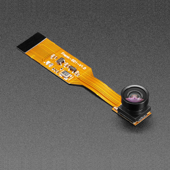
Adafruit Adafruit Zero Spy Camera for Raspberry Pi Zero (160 Degree Focal Angle)
Is your house haunted? Or, rather, are you convinced that your house is haunted but have never been able to prove it since you've never had a camera that integrated with your Raspberry Pi Zero but was still small enough that the ghosts wouldn't notice it? Luckily, the spy camera for Raspberry Pi Zero is smaller than a thumbnail with a high enough resolution to see people, ghosts, or whatever it is you're looking for. It's about the size of a cell phone camera – the module being just 8.6 x 8.6 mm – with only a 2' cable, so you can create an extra compact and sneaky little spy cam. It has a 160-degree focal angle for a very wide/distorted fisheye effect that's great for security systems or watching a big swath of the living room or roadway. Like the Raspberry Pi camera board, it attaches to your Raspberry Pi Zero v1.3 or Zero W by way of the small socket on the board's edge closest to the 'PWR in' port. This interface uses the dedicated CSI interface, which was designed especially for interfacing to cameras. The CSI bus is capable of extremely high data rates, and it exclusively carries pixel data. The camera is connected to the BCM2835 processor on the RPi via the CSI bus, a higher bandwidth link which carries pixel data from the camera back to the processor. This bus travels along the ribbon cable that attaches the camera board to the Pi. The ribbon cables are compatible with both the RPi Zero v1.3 and RPi Zero W. The sensor itself has a native resolution of 5 megapixels and has a fixed focus lens onboard. It has similar specs as the original RPi camera, but is not as high-res as the new RPi camera v2! Specifications Camera Module Dimensions: 8.6 x 8.6 mm Lens Diameter: 10 mm Total Length: 60 mm Lens Focal Angle: 160 degrees Weight: 1.9 g
€ 34,95
Members € 31,46
-
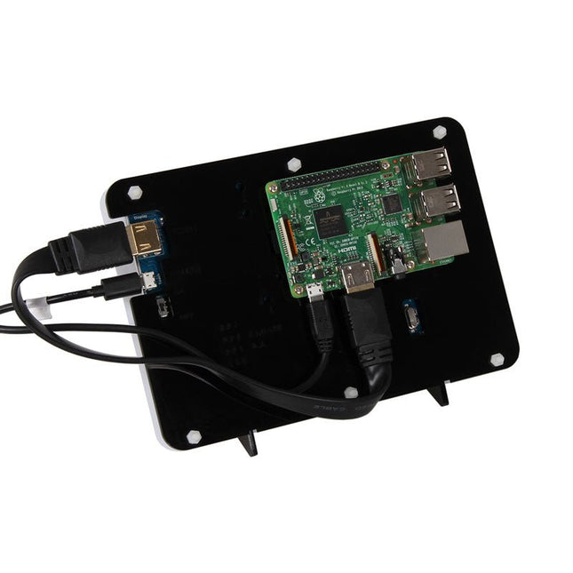
JOY-iT Case for 7" RGB-Touch-Display for Raspberry Pi
Case for 7' RGB-Touch-Display for Raspberry Pi
€ 12,95€ 6,95
Members identical
-
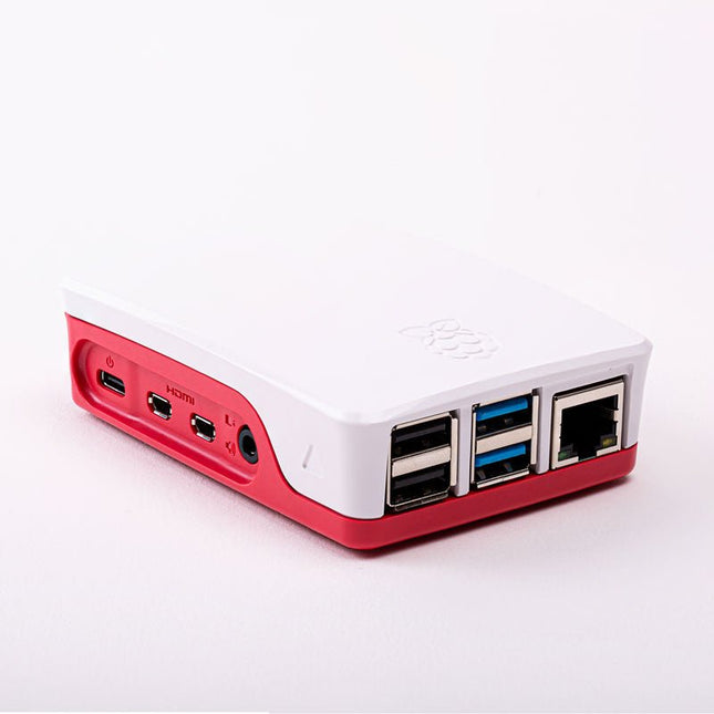
Raspberry Pi Foundation Official Case for Raspberry Pi 4 (white/red)
Official Case for Raspberry Pi 4 (white/red)
€ 7,95
Members identical
-

Elektor Digital Experiments with Digital Electronics (E-book)
The field of digital electronics is central to modern technology. This e-book presents fundamental circuits using gates, flip-flops and counters from the CMOS 4000 Series. Each of the 50 experiments has a circuit diagram as well as a detailed illustration of the circuit’s construction on solderless breadboard. Learning these fundamentals is best done using practical experiments. Building these digital circuits will improve your knowledge and will be fun to boot. Many of the circuits presented here have practical real-life applications. With a good overview of the field, you’ll be well equipped to find simple and cost-effective solutions for any application. The e-book is targeted essentially at students, trainees and anyone with an interest in and requiring an introduction to digital control electronics. Moreover, the knowledge gleaned here is the foundation for further projects in the field of microcontrollers and programming.
€ 24,95
Members € 19,96
-
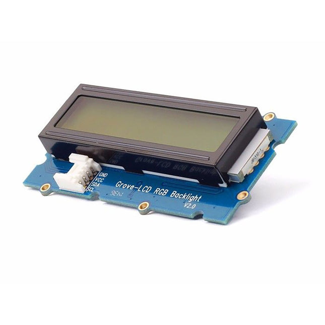
Seeed Studio Seeed Studio Grove LCD RGB Backlight (16x2 full-color Display for Arduino)
With the help of the Grove I²C connector, only 2 signal pins and 2 power pins are needed. You don't even need to care about how to connect these pins. Just plug it into the I²C interface on Seeeduino or Arduino/Raspberry Pi+baseshield via the Grove cable. No complicated wiring, no soldering, no need to worry about burning the LCD caused by the wrong current limiting resistor. Easy peasy. Specifications Battery: Exclude Input Voltage: 5 V Dimensions: 83 x 44 x 13 mm Weight: 42 g
€ 17,95
Members € 16,16
-
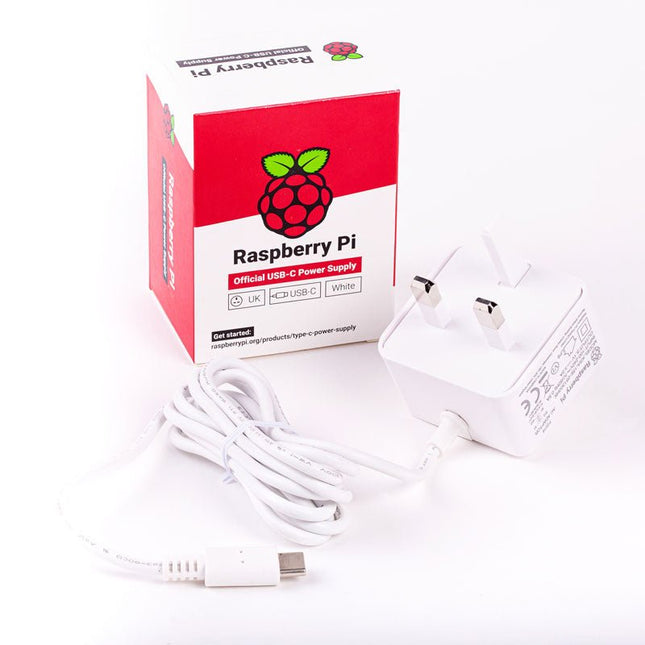
Raspberry Pi Foundation Official UK Power Supply for Raspberry Pi 4 (white)
The Raspberry Pi USB-C power supply is designed specifically to power the latest Raspberry Pi 4 Model B computers. The power supply features a USB-C cable and is available in four different models to suit different international power sockets, and in two colors. Specifications Output Output voltage +5.1 V DC Minimum load current 0 A Nominal load current 3.0 A Maximum power 15.3 W Load regulation ±5 % Line regulation ±2 % Ripple & noise 120 mVp-p Rise time 100 ms maximum to regulation limits for DC outputs Turn-on delay 3000 ms maximum at nominal input AC voltage and full load Protection Short circuit protectionOvercurrent protectionOver temperature protection Efficiency 81% minimum (output current from 100%, 75%, 50%, 25%)72% minimum at 10% load Output cable 1.5 m 18AWG Output connector USB Type-C Input Voltage range 100-240 VAC (rated)96-264 VAC (operating) Frequency 50/60 Hz ±3 Hz Current 0.5 A maximum Power consumption (no load) 0.075 W maximum Inrush current No damage shall occur, and the input fuse shall not blow Operating ambient temperature 0-40°C
€ 9,95
Members identical


-
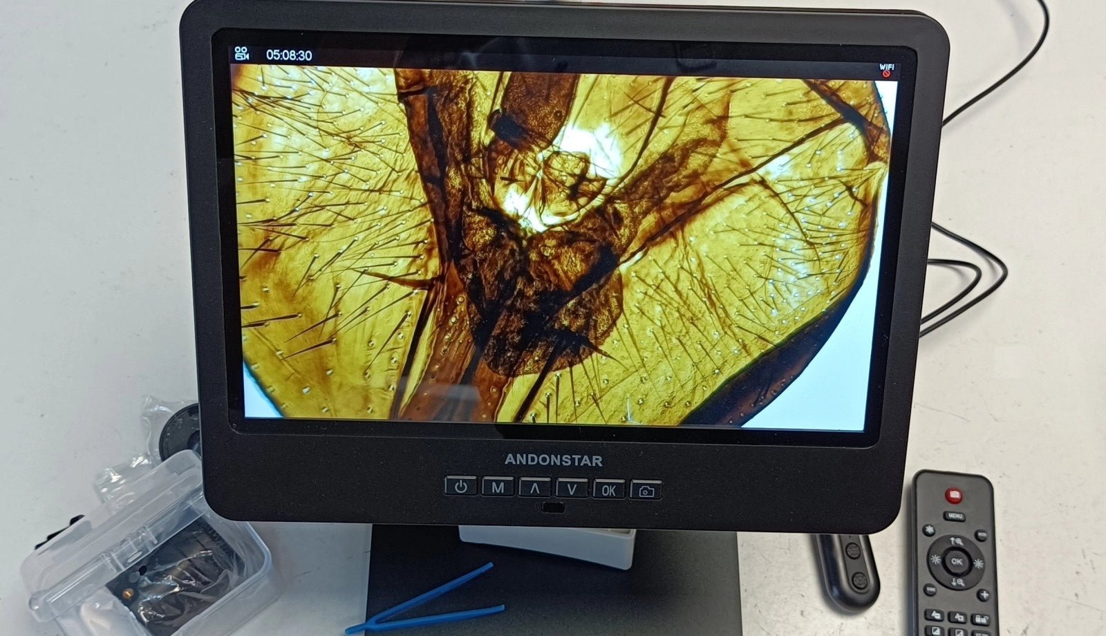
, by Clemens Valens Review: The Andonstar AD249S-M Digital Microscope Magnifies Up To 2040 Times
The Andonstar AD249S-M is a digital microscope with a 10” display and a magnification factor of up to 2040 times. It comes with three lenses,...
