Search results for "wismart OR development OR kit OR standard OR 140338 OR 91"
-
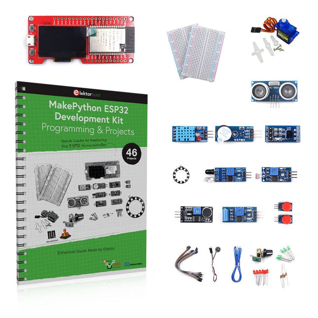
Elektor Bundles MakePython ESP32 Development Kit
Learn how to use the ESP32 Microcontroller and MicroPython programming in your future projects! The project book, written by well-known Elektor author Dogan Ibrahim, holds many software- and hardware-based projects especially developed for the MakePython ESP32 Development Kit. The kit comes with several LEDs, sensors, and actuators. The kit will help you acquire the basic knowledge to create IoT projects. The book’s fully evaluated projects feature all the supplied components. Each project includes a block diagram, a circuit diagram, a full program listing, and a complete program description. Included in the kit 1x MakePython ESP32 development board with LCD 1x Ultrasonic ranging module 1x Temperature and humidity sensor 1x Buzzer module 1x DS18B20 module 1x Infrared module 1x Potentiometer 1x WS2812 module 1x Sound sensor 1x Vibration sensor 1x Photosensitive resistance module 1x Pulse sensor 1x Servo motor 1x USB cable 2x Button 2x Breadboard 45x Jumper wire 10x Resistor 330R 10x LED (Red) 10x LED (Green) 1x Project book (206 pages) 46 Projects in the Book LED Projects Blinking LED Flashing SOS Blinking LED – using a timer Alternately flashing LEDs Button control Changing the LED flashing rate using pushbutton interrupts Chasing-LEDs Binary-counting LEDs Christmas lights (random-flashing 8 LEDs) Electronic dice Lucky day of the week Pulsewidth Modulation (PWM) Projects Generate a 1000-Hz PWM waveform with 50% duty cycle LED brightness control Measuring the frequency and duty cycle of a PWM waveform Melody maker Simple electronic organ Servo motor control Servo motor DS18B20 thermometer Analog To Digital Converter (ADC) Projects Voltmeter Plotting the analog input voltage ESP32 internal temperature sensor Ohmmeter Photosensitive resistance module Digital To Analog Converter (DAC) Projects Generating fixed voltages Generating a sawtooth-wave signal Generating a triangular-wave signal Arbitrary periodic waveform Generating a sinewave signal Generating accurate sinewave signal using timer interrupts Using The OLED Display Seconds counter Event counter DS18B20 OLED based digital thermometer ON-OFF temperature controller Measuring the temperature and humidity Ultrasonic distance measurement Height of a person (stadiometer) Heart rate (pulse) measurement Other Sensors Supplied with the Kit Theft alarm Sound-activated light Infrared obstacle avoidance with buzzer WS2812 RGB LED ring Timestamping temperature and humidity readings Network Programming Wi-Fi scanner Remote control from the Internet browser (using a smartphone or PC) – Web Server Storing temperature and humidity data in the Cloud Low-Power Operation Using a timer to wake up the processor
€ 89,95€ 64,95
Members identical
-

NXP Semiconductors NXP FRDM-MCXN947 Development Board
The FRDM-MCXN947 is a compact and versatile development board designed for rapid prototyping with MCX N94 and N54 microcontrollers. It features industry-standard headers for easy access to the MCU's I/Os, integrated open-standard serial interfaces, external flash memory, and an onboard MCU-Link debugger. Specifications Microcontroller MCX-N947 Dual Arm Cortex-M33 cores @ 150 MHz each with optimized performance efficiency, up to 2 MB dual-bank flash with optional full ECC RAM, External flash Accelerators: Neural Processing Unit, PowerQuad, Smart DMA, etc. Memory Expansion *DNP Micro SD card socket Connectivity Ethernet Phy and connector HS USB-C connectors SPI/I²C/UART connector (PMOD/mikroBUS, DNP) WiFi connector (PMOD/mikroBUS, DNP) CAN-FD transceiver Debug On-board MCU-Link debugger with CMSIS-DAP JTAG/SWD connector Sensor P3T1755 I³C/I²C Temp Sensor, Touch Pad Expansion Options Arduino Header (with FRDM expansion rows) FRDM Header FlexIO/LCD Header SmartDMA/Camera Header Pmod *DNP mikroBUS User Interface RGB user LED, plus Reset, ISP, Wakeup buttons Included 1x FRDM-MCXN947 Development Board 1x USB-C Cable 1x Quick Start Guide Downloads Datasheet Block diagram
€ 29,95€ 11,98
Members identical
-
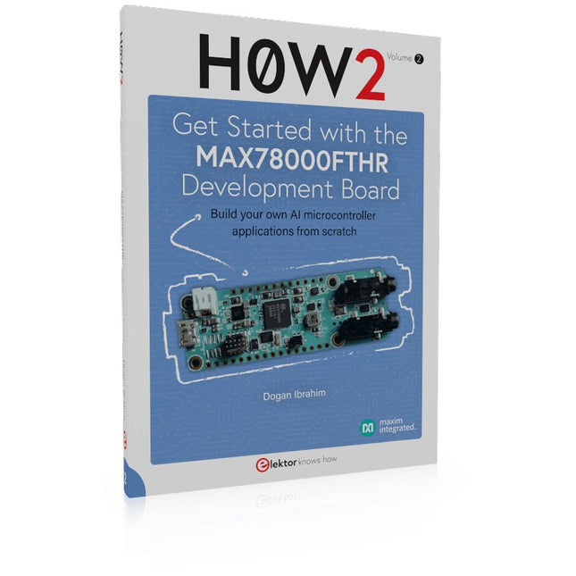
Elektor Publishing H0W2: Get Started with the MAX78000FTHR Development Board
Build your own AI microcontroller applications from scratch The MAX78000FTHR from Maxim Integrated is a small development board based on the MAX78000 MCU. The main usage of this board is in artificial intelligence applications (AI) which generally require large amounts of processing power and memory. It marries an Arm Cortex-M4 processor with a floating-point unit (FPU), convolutional neural network (CNN) accelerator, and RISC-V core into a single device. It is designed for ultra-low power consumption, making it ideal for many portable AI-based applications. This book is project-based and aims to teach the basic features of the MAX78000FTHR. It demonstrates how it can be used in various classical and AI-based projects. Each project is described in detail and complete program listings are provided. Readers should be able to use the projects as they are, or modify them to suit their applications. This book covers the following features of the MAX78000FTHR microcontroller development board: Onboard LEDs and buttons External LEDs and buttons Using analog-to-digital converters I²C projects SPI projects UART projects External interrupts and timer interrupts Using the onboard microphone Using the onboard camera Convolutional Neural Network
€ 39,95
Members € 35,96
-

Elektor Digital H0W2: Get Started with the MAX78000FTHR Development Board (E-book)
Build your own AI microcontroller applications from scratch The MAX78000FTHR from Maxim Integrated is a small development board based on the MAX78000 MCU. The main usage of this board is in artificial intelligence applications (AI) which generally require large amounts of processing power and memory. It marries an Arm Cortex-M4 processor with a floating-point unit (FPU), convolutional neural network (CNN) accelerator, and RISC-V core into a single device. It is designed for ultra-low power consumption, making it ideal for many portable AI-based applications. This book is project-based and aims to teach the basic features of the MAX78000FTHR. It demonstrates how it can be used in various classical and AI-based projects. Each project is described in detail and complete program listings are provided. Readers should be able to use the projects as they are, or modify them to suit their applications. This book covers the following features of the MAX78000FTHR microcontroller development board: Onboard LEDs and buttons External LEDs and buttons Using analog-to-digital converters I²C projects SPI projects UART projects External interrupts and timer interrupts Using the onboard microphone Using the onboard camera Convolutional Neural Network
€ 32,95
Members € 26,36
-
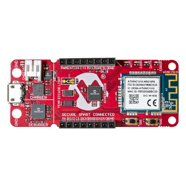
Microchip Microchip AVR-IoT WA Development Board
The AVR-IoT WA development board combines a powerful ATmega4808 AVR MCU, an ATECC608A CryptoAuthentication secure element IC and the fully certified ATWINC1510 Wi-Fi network controller – which provides the most simple and effective way to connect your embedded application to Amazon Web Services (AWS). The board also includes an on-board debugger, and requires no external hardware to program and debug the MCU. Out of the box, the MCU comes preloaded with a firmware image that enables you to quickly connect and send data to the AWS platform using the on-board temperature and light sensors. Once you are ready to build your own custom design, you can easily generate code using the free software libraries in Atmel START or MPLAB Code Configurator (MCC). The AVR-IoT WA board is supported by two award-winning Integrated Development Environments (IDEs) – Atmel Studio and Microchip MPLAB X IDE – giving you the freedom to innovate with your environment of choice. Features ATmega4808 microcontroller Four user LED’s Two mechanical buttons mikroBUS header footprint TEMT6000 Light sensor MCP9808 Temperature sensor ATECC608A CryptoAuthentication™ device WINC1510 WiFi Module On-board Debugger Auto-ID for board identification in Atmel Studio and Microchip MPLAB X One green board power and status LED Programming and debugging Virtual COM port (CDC) Two DGI GPIO lines USB and battery powered Integrated Li-Ion/LiPo battery charger
€ 39,95€ 15,98
Members identical
-
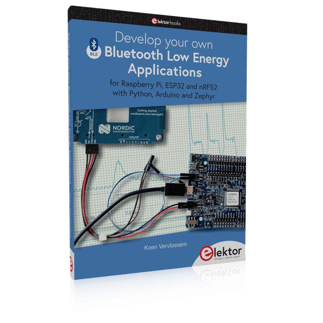
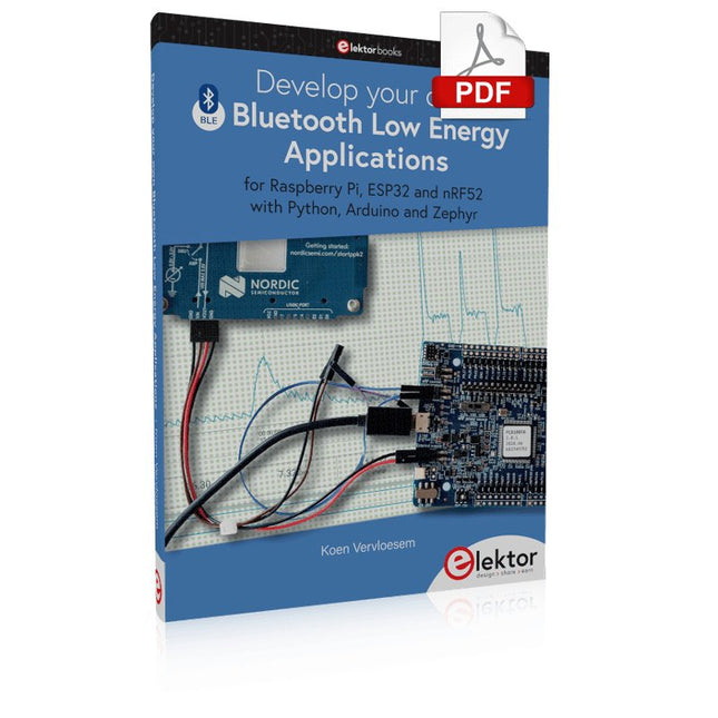
Elektor Publishing Develop your own Bluetooth Low Energy Applications
For Raspberry Pi, ESP32 and nRF52 with Python, Arduino and Zephyr Bluetooth Low Energy (BLE) radio chips are ubiquitous from Raspberry Pi to light bulbs. BLE is an elaborate technology with a comprehensive specification, but the basics are quite accessible. A progressive and systematic approach will lead you far in mastering this wireless communication technique, which is essential for working in low power scenarios. In this book, you’ll learn how to: Discover BLE devices in the neighborhood by listening to their advertisements. Create your own BLE devices advertising data. Connect to BLE devices such as heart rate monitors and proximity reporters. Create secure connections to BLE devices with encryption and authentication. Understand BLE service and profile specifications and implement them. Reverse engineer a BLE device with a proprietary implementation and control it with your own software. Make your BLE devices use as little power as possible. This book shows you the ropes of BLE programming with Python and the Bleak library on a Raspberry Pi or PC, with C++ and NimBLE-Arduino on Espressif’s ESP32 development boards, and with C on one of the development boards supported by the Zephyr real-time operating system, such as Nordic Semiconductor's nRF52 boards. Starting with a very little amount of theory, you’ll develop code right from the beginning. After you’ve completed this book, you’ll know enough to create your own BLE applications.
€ 39,95
Members € 35,96
-
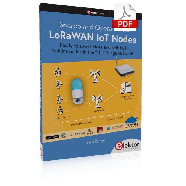
Elektor Digital Develop and Operate Your LoRaWAN IoT Nodes (E-book)
Ready-to-use devices and self-built Arduino nodes in the 'The Things Network' LoRaWAN has developed excellently as a communication solution in the IoT. The Things Network (TTN) has contributed to this. The Things Network was upgraded to The Things Stack Community Edition (TTS (CE)). The TTN V2 clusters were closed towards the end of 2021. This book shows you the necessary steps to operate LoRaWAN nodes using TTS (CE) and maybe extend the network of gateways with an own gateway. Meanwhile, there are even LoRaWAN gateways suitable for mobile use with which you can connect to the TTN server via your cell phone. The author presents several commercial LoRaWAN nodes and new, low-cost and battery-powered hardware for building autonomous LoRaWAN nodes. Registering LoRaWAN nodes and gateways in the TTS (CE), providing the collected data via MQTT and visualization via Node-RED, Cayenne, Thingspeak, and Datacake enable complex IoT projects and completely new applications at very low cost. This book will enable you to provide and visualize data collected with battery-powered sensors (LoRaWAN nodes) wirelessly on the Internet. You will learn the basics for smart city and IoT applications that enable, for example, the measurement of air quality, water levels, snow depths, the determination of free parking spaces (smart parking), and the intelligent control of street lighting (smart lighting), among others.
€ 32,95
Members € 26,36
-
Elektor Digital Develop your own Bluetooth Low Energy Applications (E-book)
For Raspberry Pi, ESP32 and nRF52 with Python, Arduino and Zephyr Bluetooth Low Energy (BLE) radio chips are ubiquitous from Raspberry Pi to light bulbs. BLE is an elaborate technology with a comprehensive specification, but the basics are quite accessible. A progressive and systematic approach will lead you far in mastering this wireless communication technique, which is essential for working in low power scenarios. In this book, you’ll learn how to: Discover BLE devices in the neighborhood by listening to their advertisements. Create your own BLE devices advertising data. Connect to BLE devices such as heart rate monitors and proximity reporters. Create secure connections to BLE devices with encryption and authentication. Understand BLE service and profile specifications and implement them. Reverse engineer a BLE device with a proprietary implementation and control it with your own software. Make your BLE devices use as little power as possible. This book shows you the ropes of BLE programming with Python and the Bleak library on a Raspberry Pi or PC, with C++ and NimBLE-Arduino on Espressif’s ESP32 development boards, and with C on one of the development boards supported by the Zephyr real-time operating system, such as Nordic Semiconductor's nRF52 boards. Starting with a very little amount of theory, you’ll develop code right from the beginning. After you’ve completed this book, you’ll know enough to create your own BLE applications.
€ 32,95
Members € 26,36


-
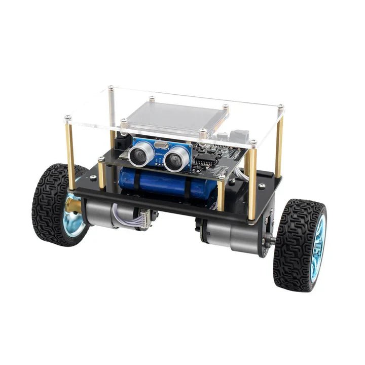
, by Lobna Belarbi Affordable Robot Kits to Kickstart Your Robotics Journey
Robotics is an exciting and rewarding field, but getting started can be intimidating—especially when it comes to choosing the right kit. Fortunately, Elektor offers a...
-
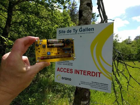
, by Clemens Valens Review: Detect Radiation with the MightyOhm Geiger Counter Kit
The MightyOhm Geiger Counter is a device for detecting beta and gamma radiation levels. Because radiation is so harmful, you may want to keep an...
-
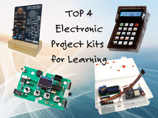
, by Udo Bormann Top 4 Elektor Electronics Project Kits for Learning and Skill Development
Discover four of Elektor’s most exciting electronics kits — from IoT and Arduino to retro logic and motion control. Whether you're just starting out or...
-
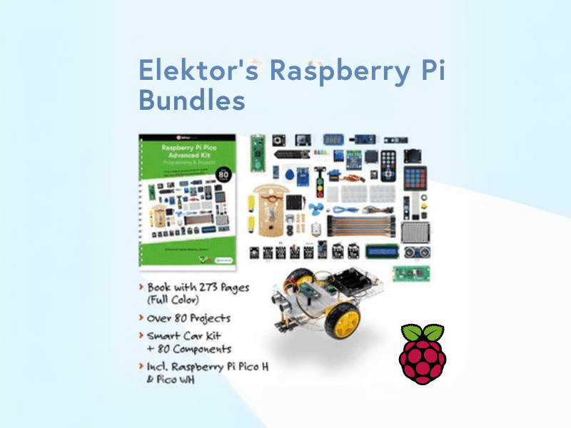
, by Lobna Belarbi Elektor’s Raspberry Pi Bundles: From Beginner-Friendly to Advanced Kits
Find the Perfect Raspberry Pi Bundle for Your Skill Level Whether you're a beginner eager to explore the world of Raspberry Pi or an advanced...


