This book details the use of the ARM Cortex-M family of processors and the Arduino Uno in practical CAN bus based projects. Inside, it gives a detailed introduction to the architecture of the Cortex-M family whilst providing examples of popular hardware and software development kits. Using these kits helps to simplify the embedded design cycle considerably and makes it easier to develop, debug, and test a CAN bus based project. The architecture of the highly popular ARM Cortex-M processor STM32F407VGT6 is described at a high level by considering its various modules. In addition, the use of the mikroC Pro for ARM and Arduino Uno CAN bus library of functions are described in detail.
This book is written for students, for practising engineers, for hobbyists, and for everyone else who may need to learn more about the CAN bus and its applications. The book assumes that the reader has some knowledge of basic electronics. Knowledge of the C programming language will be useful in later chapters of the book, and familiarity with at least one microcontroller will be an advantage, especially if the reader intends to develop microcontroller based projects using CAN bus.
The book should be useful source of reference to anyone interested in finding an answer to one or more of the following questions:
What bus systems are available for the automotive industry?
What are the principles of the CAN bus?
What types of frames (or data packets) are available in a CAN bus system?
How can errors be detected in a CAN bus system and how reliable is a CAN bus system?
What types of CAN bus controllers are there?
What are the advantages of the ARM Cortex-M microcontrollers?
How can one create a CAN bus project using an ARM microcontroller?
How can one create a CAN bus project using an Arduino microcontroller?
How can one monitor data on the CAN bus?
Contents Basic principles A connector is an electromechanical system that provides a separable connection between two subsystems of an electronic device without an unacceptable effect on the performance of the device. It will be shown that there are a lot of complex parameters to handle properly to make this statement true. Design / Selection / Assembly This chapter provides an overview of design and material requirements for contact finishes, contact springs and connector housings as well as the major degradation mechanisms for these connector components. To complete this chapter, material selection criteria for each will also be reviewed. Additionally the Level of Interconnection (LOI) was integrated into this chapter as it addresses, where the connector is used within an electronic system and therefore influences the requirements and durability of the connector depending on its use. Applications This chapter is heading to the practical work and shows how customers use connectors in their applications to offer some possibilities and to ease your daily work. Additionally it contains some special topics like tin-whisker or impedance of ZIF cable to offer you extended background knowledge.
Technology is constantly changing. New microcontrollers become available every year and old ones become redundant. The one thing that has stayed the same is the C programming language used to program these microcontrollers. If you would like to learn this standard language to program microcontrollers, then this book is for you!
ARM microcontrollers are available from a large number of manufacturers. They are 32-bit microcontrollers and usually contain a decent amount of memory and a large number of on-chip peripherals. Although this book concentrates on ARM microcontrollers from Atmel, the C programming language applies equally to other manufacturer’s ARMs as well as other microcontrollers.
Features of this book
Use only free or open source software.
Learn how to download, set up and use free C programming tools.
Start learning the C language to write simple PC programs before tackling embedded programming - no need to buy an embedded system right away!
Start learning to program from the very first chapter with simple programs and slowly build from there.
No programming experience is necessary!
Learn by doing - type and run the example programs and exercises.
Sample programs and exercises can be downloaded from the Internet.
A fun way to learn the C programming language.
Ideal for electronic hobbyists, students and engineers wanting to learn the C programming language in an embedded environment on ARM microcontrollers.
The Raspberry Pi Monitor is a 15.6-inch Full HD computer display. User-friendly, versatile, compact and affordable, it is the perfect desktop display companion for both Raspberry Pi computers and other devices.
With built-in audio via two front-facing speakers, and VESA and screw mounting options as well as an integrated angle-adjustable stand, the Raspberry Pi Monitor is ideal for desktop use or for integration into projects and systems. It can be powered directly from a Raspberry Pi, or by a separate power supply.
Features
15.6-inch full HD 1080p IPS display
Integrated angle-adjustable stand
Built-in audio via two front-facing speakers
Audio out via 3.5 mm jack
Full-size HDMI input
VESA and screw mounting options
Volume and brightness control buttons
USB-C power cable
Specifications
Display
Screen size: 15.6 inches, 16:9 ratio
Panel type: IPS LCD with anti-glare coating
Display resolution: 1920 x 1080
Color depth: 16.2M
Brightness (typical): 250 nits
Color gamut: 45%
Viewing angle: 80°
Power
1.5 A/5 V
Can be powered directly from a Raspberry Pi USB port (max 60% brightness, 50% volume) or by a separate power supply (max 100% brightness, 100% volume)
Connectivity
Standard HDMI port (1.4 compliant)
3.5 mm stereo headphone jack
USB-C (power in)
Audio
2x 1.2 W integrated speakers
Support for 44.1 kHz, 48 kHz, and 96 kHz sample rates
Downloads
Datasheet
PCBite is the complete solution handling your circuit board during the development phase. Powerful magnets together with a stainless base plate makes the system flexible, mobile and user friendly.
The holder can easily be repositioned to handle circuit boards of varying shape and sizes.
The probes are steady but yet flexible made for instant measurements or total hands-free operations together with your multimeter or prefered tool.
Included
4x PCBite holder
2x Banana to DuPont test wires red/black
2x SP10 probe with red/black probe head and pin tipped test needles
2x Extra crown tipped test needle
1x Set of yellow insulation washers
1x Large Baseplate (A4)
1x Microfiber cloth
Downloads
User Guide
With 20+ Practical Projects in Logic and Circuit Design
This book is a practical guide to digital electronics, covering the essential components of modern digital systems: number systems, logic gates, Boolean algebra, combinational and sequential logic, and more.
Through more than 20 structured projects, you’ll design and build digital systems using real-world components such as logic gates, multiplexers, decoders, flip-flops, counters, and shift registers. The projects range from basic LED logic circuits to digital locks, display systems, traffic light controllers, and timing-based designs.
Selected projects introduce the use of tools such as CircuitVerse for circuit simulation, while several designs make use of 74HC-series logic devices, commonly used in digital hardware prototyping.
Inside, you’ll find:
Clear coverage of number systems and binary arithmetic
Logic gate fundamentals and universal gate implementations
Step-by-step projects using flip-flops, counters, and registers
Real-world design with 74HC-series logic chips
Techniques for designing combinational and sequential systems
This book takes a design-first, application-driven approach to digital electronics—built around working circuits, tested logic, and hands-on experimentation.
UNDERSTANDING THE NEURONS IN NEURAL NETWORKS (PART 1)Artificial Neurons
EMC PRE-COMPLIANCE TEST FOR YOUR DC-POWERED PROJECT (PART 1)Dual DC LISN
ELECTRONIC LOAD FOR DC AND ACUp to 400 V and 10 A (Peak)
STARTING OUT IN ELECTRONICSEasier Than Imagined! ...Taking on the Choke!
IMAGE PROCESSING WITH THE NVIDIA JETSON NANO (PART 1)The Hardware and Software
AN IN-DEPTH LOOK AT MAINS TRANSFORMERSHow Do They Behave When They Are Switched On and Off?
YES WE CAN WITH PICAN 3A CAN Bus HAT for the Raspberry Pi 4
BALCONY POWER PLANTDIY Solar Balcony = Speedy Payback!
IMAGING AND VIDEO-STREAMING WITH A RASPBERRY PI 4The Raspberry Pi High-Quality Camera in Practice
USING DISPLAYS IN RASPBERRY PI PROJECTSSample Chapter: Organic Light Emitting Diode Displays (OLED)
HANDS ON THE PARALLAX PROPELLER 2 (PART 4)Sending Strings
ELEKTOR @ 60A Look Back at Previous Septembers
HOMELAB TOURSIn the Friesian Countryside, Where the Tubes Bloom ...
HYBRIDSPeculiar Parts, the series
A COMPASS ROSE USING THE GY-271Or Why We Move in Figures of Eight to Calibrate a Sensor
FINDING YOUR FOOTPRINTCalculate the Carbon Footprint of Your Electronics
ESP32-CONNECTED THERMOSTATKeep Your Wine at the Right Temperature!
MAGNETIC LEVITATION THE DIGITAL WAYESP32 Pico Replaces the Analog Comparator
ULTIMATE ARDUINO UNO HARDWARE MANUALSample Chapter: Main Microcontroller Bootloader
MICROPYTHON FOR THE ESP32 AND FRIENDS (PART 2)Control Matrix Displays Easily
MADMACHINE SWIFTIO BOARDModern Language Meets Modern Hardware
FROM LIFE’S EXPERIENCEOn-Again, Off-Again Relationship
HEXADOKUThe Original Elektorized Sudoku
Build your own AI microcontroller applications from scratch
The MAX78000FTHR from Maxim Integrated is a small development board based on the MAX78000 MCU. The main usage of this board is in artificial intelligence applications (AI) which generally require large amounts of processing power and memory. It marries an Arm Cortex-M4 processor with a floating-point unit (FPU), convolutional neural network (CNN) accelerator, and RISC-V core into a single device. It is designed for ultra-low power consumption, making it ideal for many portable AI-based applications.
This book is project-based and aims to teach the basic features of the MAX78000FTHR. It demonstrates how it can be used in various classical and AI-based projects. Each project is described in detail and complete program listings are provided. Readers should be able to use the projects as they are, or modify them to suit their applications. This book covers the following features of the MAX78000FTHR microcontroller development board:
Onboard LEDs and buttons
External LEDs and buttons
Using analog-to-digital converters
I²C projects
SPI projects
UART projects
External interrupts and timer interrupts
Using the onboard microphone
Using the onboard camera
Convolutional Neural Network
This hands-on bundle lets you build real Edge AI applications with the Raspberry Pi
Raspberry Pi AI HAT+ (13 TOPS)
The Raspberry Pi AI HAT+ (13 TOPS) is an expansion board designed for the Raspberry Pi 5, featuring an integrated Hailo AI accelerator. This add-on offers a cost-effective, efficient, and accessible approach to incorporating high-performance AI capabilities, with applications spanning process control, security, home automation, and robotics.
The AI HAT+ connects via the Raspberry Pi 5’s PCIe Gen3 interface. When the Raspberry Pi 5 is running a current version of the Raspberry Pi OS, it automatically detects the onboard Hailo accelerator, making the neural processing unit (NPU) available for AI tasks. Additionally, the rpicam-apps camera applications included in Raspberry Pi OS seamlessly support the AI module, automatically using the NPU for compatible post-processing functions.
Raspberry Pi Camera Module 3
Raspberry Pi Camera Module 3 is a compact camera from Raspberry Pi. It offers an IMX708 12-megapixel sensor with HDR, and features phase detection autofocus. Camera Module 3 is available in standard and wide-angle variants, both of which are available with or without an infrared cut filter.
Camera Module 3 can be used to take full HD video as well as stills photographs, and features an HDR mode up to 3 megapixels. Its operation is fully supported by the libcamera library, including Camera Module 3’s rapid autofocus feature: this makes it easy for beginners to use, while offering plenty for advanced users. Camera Module 3 is compatible with all Raspberry Pi computers.
Book: Edge AI Made Practical – AI Projects for the Raspberry Pi with the AI HAT+
Edge AI is transforming everyday devices by putting intelligence where it matters most: directly inside the hardware. With on-device inference, a camera can recognize a visitor instantly, a phone can translate speech without streaming audio to the cloud, and a wearable can detect anomalies in real time—fast, private, and reliable even when the network disappears.
This book is your practical guide to building exactly those kinds of systems with the Raspberry Pi AI HAT+ and the Hailo-8L accelerator. You’ll start with clear foundations: core AI and machine-learning concepts, how neural networks work, and what truly distinguishes Edge AI from cloud AI—plus an honest look at ethical considerations and future impacts.
This bundle contains:
Book: Edge AI Made Practical
Raspberry Pi AI HAT+ (13 TOPS)
Raspberry Pi Camera Module 3
Active Cooler for Raspberry Pi 5
FPC Display Cable for Raspberry Pi 5 (300 mm)
Elektor Component Kit
40-pin GPIO Header
Traffic Light Module
LED red 5 V with built-in resistor
LED yellow 5 V with built-in resistor
LED green 5 V with built-in resistor
LED blue 5 V with built-in resistor
Breadboard (400 Tie-points)
10 Dupont wires male-female
DHT22 sensor module
Servo motor
Required
Raspberry Pi 5
Elektor GREEN and GOLD members can download their digital edition here.
Not a member yet? Click here.
STM32 Wireless Innovation Design Contest Winners
In-Circuit LC MeterA Prototype Study
The AmpVolt Modular DC Power Meter (Part 1)Measure DC Power and Energy Consumption Up to 50 V and 5 A
embedded world 2024
Repairing Electronic EquipmentTools, Techniques and Tips
Starting Out in Electronics…...Continues the Opamp Theory
A Simple DDS Signal GeneratorDirect Digital Synthesis in Its Purest Form
Sparkplug at a GlanceA Specification for MQTT Data
The CRTCPeculiar Parts, the Series
Radar-Controlled LightingAutomatic Stairway Light With Human Presence Detection
Digital Bubble Level and Active Stroboscopic Disc for TurntablesFine-Tune Your Record Player With This All-In-One Tool
Open Source and Its Significance for the Electronics Industry (2)
M12 Circular Connector With A-codingFirst Choice for Industrial Applications
The Arduino-Inside Measurement LabAn 8-in-1 Test & Measurement Instrument for the Electronics Workbench
Sound Card Performs Gain/Phase and Impedance AnalysisFor Frequencies From 100 Hz to 90 kHz
Measuring pH Value With the Arduino UNO R4Check the Quality of Your Water
From Life’s ExperiencePangpong Butt Launcher
FNIRSI 1014D Digital Storage OscilloscopeGood Performance for Tight Budgets
2024: An AI OdysseyGetting Object Detection Up and Running
10 MHz Reference GeneratorHighly Accurate, With Distributor and Galvanic Isolation
Project Update #2: ESP32-Based Energy MeterSome Enhancements
Err-lectronicsCorrections, Updates, and Readers’ Letters
An Interview with Eben Upton, CEO of Raspberry PiRaspberry Pi 5 and Beyond
The Elektor Arduino Nano MCCAB Training Board contains all the components (incl. Arduino Nano) required for the exercises in the "Microcontrollers Hands-on Course for Arduino Starters", such as light-emitting diodes, switches, pushbuttons, acoustic signal transmitters, etc. External sensors, motors or assemblies can also be queried or controlled with this microcontroller training system.
Specifications (Arduino Nano MCCAB Training Board)
Power Supply
Via the USB connection of the connected PC or an external power supply unit (not included)
Operating Voltage
+5 Vcc
Input Voltage
All inputs
0 V to +5 V
VX1 and VX2
+8 V to +12 V (only when using an external power supply)
Hardware periphery
LCD
2x16 characters
Potentiometer P1 & P2
JP3: selection of operating voltage of P1 & P2
Distributor
SV4: Distributor for the operating voltagesSV5, SV6: Distributor for the inputs/outputs of the microcontroller
Switches and buttons
RESET button on the Arduino Nano module 6x pushbutton switches K1 ... K6 6x slide switches S1 ... S6 JP2: Connection of the switches with the inputs of the microcontroller
Buzzer
Piezo buzzer Buzzer1 with jumper on JP6
Indicator lights
11 x LED: Status indicator for the inputs/outputs LED L on the Arduino Nano module, connected to GPIO D13 JP6: Connection of LEDs LD10 ... LD20 with GPIOs D2 ... D12
Serial interfacesSPI & I²C
JP4: Selection of the signal at pin X of the SPI connector SV12 SV9 to SV12: SPI interface (3.3 V/5 V) or I²C interface
Switching output for external devices
SV1, SV7: Switching output (maximum +24 V/160 mA, externally supplied) SV2: 2x13 pins for connection of external modules
3x3 LED matrix(9 red LEDs)
SV3: Columns of the 3x3 LED matrix (outputs D6 ... D8) JP1: Connection of the rows with the GPIOs D3 ... D5
Software
Library MCCABLib
Control of hardware components (switches, buttons, LEDs, 3x3 LED matrix, buzzer) on the MCCAB Training Board
Operating Temperature
Up to +40 °C
Dimensions
100 x 100 x 20 mm
Specifications (Arduino Nano)
Microcontroller
ATmega328P
Architecture
AVR
Operating Voltage
5 V
Flash Memory
32 KB, of which 2 KB used by bootloader
SRAM
2 KB
Clock Speed
16 MHz
Analog IN Pins
8
EEPROM
1 KB
DC Current per I/O Pins
40 mA on one I/O pin, total maximum 200 mA on all pins together
Input Voltage
7-12 V
Digital I/O Pins
22 (6 of which are PWM)
PWM Output
6
Power Consumption
19 mA
Dimensions
18 x 45 mm
Weight
7 g
Included
1x Elektor Arduino Nano Training Board MCCAB
1x Arduino Nano
Architecture, Programming and Applications
The MSP430 is a popular family of microcontrollers from Texas Instruments. In this book we will work with the smallest type, which is the powerful MSP430G2553. We will look at the capabilities of this microcontroller in detail, as it is well-suited for self-made projects because it is available in a P-DIP20 package.
We will take a closer look at the microcontroller and then build, step by step, some interesting applications, including a 'Hello World' blinking LED and a nice clock application, which can calculate the day of the week based on the date.
You also will learn how to create code for the MSP microcontroller in assembler. In addition to that, we will work with the MSP-Arduino IDE, which makes it quite easy to create fast applications without special in-depth knowledge of the microcontrollers.
All the code used in the book is available for download from the Elektor website.
The Controller Area Network (CAN) was originally developed to be used as a vehicle data bus system in passenger cars. Today, CAN controllers are available from over 20 manufacturers, and CAN is finding applications in other fields, such as medical, aerospace, process control, automation, and so on.
This book is written for students, for practising engineers, for hobbyists, and for everyone else who may be interested to learn more about the CAN bus and its applications.
The aim of this book is to teach you the basic principles of CAN networks and in addition the development of microcontroller based projects using the CAN bus. In summary, this book enables the reader to:
Learn the theory of the CAN bus used in automotive industry
Learn the principles, operation, and programming of microcontrollers
Design complete microcontroller based projects using the C language
Develop complete real CAN bus projects using microcontrollers
Learn the principles of OBD systems used to debug vehicle electronics
You will learn how to design microcontroller based CAN bus nodes, build a CAN bus, develop high-level programs, and then exchange data in real-time over the bus. You will also learn how to build microcontroller hardware and interface it to LEDs, LCDs, and A/D converters.
The book assumes that the reader has some knowledge on basic electronics. Knowledge of the C programming language will be useful in later chapters of the book, and familiarity with at least one member of the PIC series of microcontrollers will be an advantage, especially if the reader intends to develop microcontroller based projects using the CAN bus.
Based on PIC microcontrollers and Arduino
Every mobile phone includes a GSM/GPRS modem which enables the phone to communicate with the external world. With the help of the GSM modems, users can establish audio conversations and send and receive SMS text messages. In addition, the GPRS modem enables users to connect to the internet and to send and receive large files such as pictures and video over the internet.
This book is aimed for the people who may want to learn how to use the GSM/GPRS modems in microcontroller based projects. Two types of popular microcontroller families are considered in the e-book: PIC microcontrollers, and the Arduino. The highly popular mid-performance PIC18F87J50 microcontroller is used in PIC based projects together with a GSM Click board. In addition, the SIM900 GSM/GPRS shield is used with the Arduino Uno projects. Both GSM and GPRS based projects are included in the e-book.
The book will enable you to control equipment remotely by sending SMS messages from your mobile phone to the microcontroller, send the ambient temperature readings from the microcontroller to a mobile phone as SMS messages, use the GPRS commands to access the internet from a microcontroller, send temperature readings to the cloud using UDP and TCP protocols and so on.
It is assumed that the reader has some basic working knowledge of the C language and the use of microcontrollers in simple projects. Although not necessary, knowledge of at least one member of the PIC microcontroller family and the Arduino Uno will be an advantage. It will also be useful if the user has some knowledge of basic electronics.
The SEQURE T55 Smart Mini Temperature Adjustable Soldering Hot Plate is a compact and efficient tool designed for precise preheating and desoldering tasks. With its adjustable temperature range from 50°C to 280°C (122°F to 536°F), it is suitable for various applications, e.g. cell phone repair, PCB assembly, etc.
Features
Adjustable heating temperature range: 50°C to 280°C (122°F to 536°F)
Equipped with a heat-resistant ceramic temperature sensor, ensuring high-accuracy data measurement under continuous high temperatures.
Automatically stops heating after reaching the preset working time.
Supports PD, QC, and DC (max 25 V).
Intelligent temperature control algorithm for temperature compensation and power adjustment.
128 x 32 resolution OLED display with a built-in buzzer to indicate operating status.
°C/°F conversion
Specifications
Heating Area
55 x 55 mm
Working Temperature
50-280°C (122-536°F)
Max Voltage
25 V
Max Power
95 W
Recommend Voltage
19-25 V
PD Power Supply
PD 20 V ≥3A
Power Supply Modes
PD, QC, DC
Interface
USB-C
Display
128 x 32 OLED
Menu Languages
English, Russian, and Chinese
Dimensions
55 x 60 x 37 mm
Weight
92 g
Included
1x SEQURE T55 Smart Mini Soldering Hot Plate
1x PD 65 W Power Supply (EU)
1x Fast Charging Cable (100 W/5 A)
Elektor GREEN and GOLD members can download their digital edition here.
Not a member yet? Click here.
DIY Solar Energy StorageBuild Your Own Energy Store for a PV Solar Array
Solar Module SimulatorA Solution for Testing and Optimizing MPP Trackers and Inverters
The STM32 Edge AI ContestExplore the new STM32N6 and Compete for a Share of €5,000 in Prizes!
Widening the BandgapWhy There Is So Much Interest in SiC and GaN
Notebook Power BankExtend the Life of Your Aged Laptop
Medical RobotsOvercoming Technical and Regulatory Hurdles
Frost Guard for Fruit Plants With Temperature Data Logger
The Analog ThingThe Arduino of Analog Computing?
Energy Saving Relay DriverSaves 90% of Relay Drive Power
Improving the ET5410A+ DC loadKeep Cool and Be Quiet, Please
electronica 2024 in Review
Electromagnetic CompatibilityEMC in a Nutshell!
Starting Out in Electronics……Filters Actively
Reducing Power Dissipation With Dropping CapacitorsA Clever Use of Capacitive Reactance
The Affordable MCP4725 12-Bit Digital-to-Analog ConverterAn EEPROM Feature Enables Safe Switch-On Behavior
Fnirsi LCR-ST1 Smart LCR SMD Tweezers
Raspberry Pi-Based Private Test & Measurement LabFirst Things First: The ADC
Electronic Load ResistorAn Out-of-the-Box Project
2025: An AI OdysseySome Projects to See in the New Year
AmpVolt v2.0 Project Update100 Amps and Beyond!
Err-lectronicsCorrections, Updates, and Readers’ Letters
Unveiling Ethical TransparencyInsights from Ethics in Electronics’s 2024 Survey
Elektor Audio DSP FX Processor Board (2)Creating Applications
ARM Cortex-M Embedded Design from 0 to 1
Hobbyists can mash together amazing functional systems using platforms like Arduino or Raspberry Pi, but it is imperative that engineers and product designers understand the foundational knowledge of embedded design. There are very few resources available that describe the thinking, strategies, and processes to take an idea through hardware design and low-level driver development, and successfully build a complete embedded system. Many engineers end up learning the hard way, or never really learn at all.
ARM processors are essentially ubiquitous in embedded systems. Design engineers building novel devices must understand the fundamentals of these systems and be able to break down large, complicated ideas into manageable pieces. Successful product development means traversing a huge amount of documentation to understand how to accomplish what you need, then put everything together to create a robust system that will reliably operate and be maintainable for years to come.
This book is a case study in embedded design including discussion of the hardware, processor initialization, low‑level driver development, and application interface design for a product. Though we describe this through a specific application of a Cortex-M3 development board, our mission is to help the reader build foundational skills critical to being an excellent product developer. The completed development board is available to maximize the impact of this book, and the working platform that you create can then be used as a base for further development and learning.
The Embedded in Embedded program is about teaching fundamental skill sets to help engineers build a solid foundation of knowledge that can be applied in any design environment. With nearly 20 years of experience in the industry, the author communicates the critical skill development that is demanded by companies and essential to successful design. This book is as much about building a great design process, critical thinking, and even social considerations important to developers as it is about technical hardware and firmware design.
Downloads
EiE Software Archive (200 MB)
IAR ARM 8.10.1 (Recommended IDE version to use) (1.2 GB)
IAR ARM 7.20.1 (Optional IDE version to use) (600 MB)
Learn KiCad with Peter Dalmaris
The Academy Pro Box "Design PCBs like a Pro" offers a complete, structured training programme in PCB design, combining online learning with practical application. Based on Peter Dalmaris’ KiCad course, the 15-week programme integrates video lessons, printed materials (2 books), and hands-on projects to ensure participants not only understand the theory but also develop the skills to apply it in practice.
Unlike standard courses, the Academy Pro Box provides a guided learning path with weekly milestones and physical components to design, test, and produce working PCBs. This approach supports a deeper learning experience and better knowledge retention.
The box is ideal for engineers, students, and professionals who want to develop practical PCB design expertise using open-source tools. With the added option to have their final project manufactured, participants complete the programme with real results – ready for use, testing, or further development.
Learn by doing
Build skills. Design real boards. Generate Gerbers. Place your first order. This isn’t just a course – it’s a complete project journey from idea to product.
You’ll walk away with:
Working knowledge of KiCad’s tools
Confidence designing your own PCBs
A fully manufacturable circuit board – made by you
What's inside the Box (Course)?
Both volumes of "KiCad Like a Pro" (valued at €105)
Vol 1: Fundamentals and Projects
Vol 2: Advanced Projects and Recipes
Coupon code to join the bestselling KiCad 9 online course by Peter Dalmaris on Udemy, featuring 20+ hours of video training. You'll complete three full design projects:
Breadboard Power Supply
Tiny Solar Power Supply
Datalogger with EEPROM and Clock
Voucher from Eurocircuits for the production of PCBs (worth €85 excl. VAT)
Learning Material (of this Box/Course)
15-Week Learning Program
▶ Click here to open
Week 1: Setup, Fundamentals, and First Steps in PCB Design
Week 2: Starting Your First PCB Project – Schematic Capture
Week 3: PCB Layout – From Netlist to Board Design
Week 4: Design Principles, Libraries, and Workflow
Week 5: Your First Real-World PCB Project
Week 6: Custom Libraries – Symbols, Footprints, and Workflow
Week 7: Advanced Tools – Net Classes, Rules, Zones, Routing
Week 8: Manufacturing Files, BOMs, and PCB Ordering
Week 9: Advanced Finishing Techniques – Graphics, Refinement, and Production Quality
Week 10: Tiny Solar Power Supply – From Schematic to Layout
Week 11: Tiny Solar Power Supply – PCB Layout and Production Prep
Week 12: ESP32 Clone Project – Schematic Design and Layout Prep
Week 13: ESP32 Clone – PCB Layout and Manufacturing Prep
Week 14: Final Improvements and Advanced Features
Week 15: Productivity Tools, Simulation, and Automation
KiCad Course with 18 Lessons on Udemy (by Peter Dalmaris)
▶ Click here to open
Introduction
Getting started with PCB design
Getting started with KiCad
Project: A hands-on tour of KiCad (Schematic Design)
Project: A hands-on tour of KiCad (Layout)
Design principles and PCB terms
Design workflow and considerations
Fundamental KiCad how-to: Symbols and Eeschema
Fundamental KiCad how-to: Footprints and Pcbnew
Project: Design a simple breadboard power supply PCB
Project: Tiny Solar Power Supply
Project: MCU datalogger with build-in 512K EEPROM and clock
Recipes
KiCad 9 new features and improvements
Legacy (from previous versions of KiCad)
KiCad 7 update (Legacy)
(Legacy) Gettings started with KiCad
Bonus lecture
About the Author
Dr. Peter Dalmaris, PhD is an educator, an electrical engineer and Maker. Creator of online video courses on DIY electronics and author of several technical books. As a Chief Tech Explorer since 2013 at Tech Explorations, the company he founded in Sydney, Australia, Peter's mission is to explore technology and help educate the world.
What is Elektor Academy Pro?
Elektor Academy Pro delivers specialized learning solutions designed for professionals, engineering teams, and technical experts in the electronics and embedded systems industry. It enables individuals and organizations to expand their practical knowledge, enhance their skills, and stay ahead of the curve through high-quality resources and hands-on training tools.
From real-world projects and expert-led courses to in-depth technical insights, Elektor empowers engineers to tackle today’s electronics and embedded systems challenges. Our educational offerings include Academy Books, Pro Boxes, Webinars, Conferences, and industry-focused B2B magazines – all created with professional development in mind.
Whether you're an engineer, R&D specialist, or technical decision-maker, Elektor Academy Pro bridges the gap between theory and practice, helping you master emerging technologies and drive innovation within your organization.
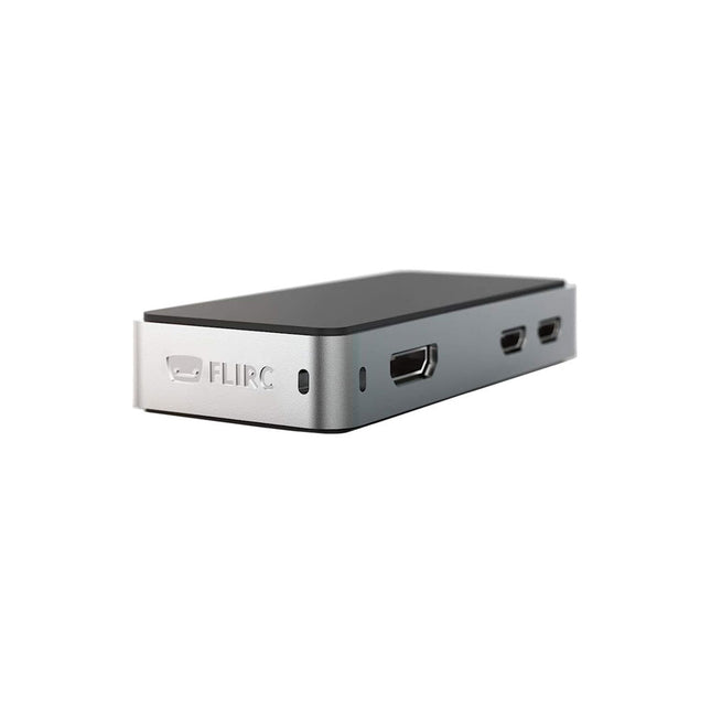
The FLIRC Raspberry Pi Zero Case is compatible with Raspberry Pi Zero W and the newer Raspberry Pi Zero 2 W.
The design of the FLIRC Zero Case is based on the original FLIRC case. As with the original, the aluminum housing serves as protection and, thanks to the contact point on the processor, as a passive cooler. Ideal for silent operation.
In addition to a normal cover that encloses and protects the Raspberry Pi Zero, there is a second cover that allows access to the GPIO pins through a small opening.
Elektor GREEN and GOLD members can download their digital edition here.
Not a member yet? Click here.
For Eyes and Ears
Video Output with Microcontrollers (1)Composite Video
electronica 2022News from the world’s leading electronics trade show
ESP32 CameraSo Simple, It Doesn’t Even Have to Use Wi-Fi
ATX Power Supply for Raspberry Pi
32 Ω Headphone AmplifierSimple But High-Quality 3-Chip Solution
SDR Radio-Controlled clocksFive Time Signals, Six Displays
Starting Out in ElectronicsSpecial Diodes
From Life's ExperienceMusings on the Quality of Things
Reverse-Engineering a Bluetooth Low Energy LED BadgeHow to Control a BLE Device with a Python Script
MakePython ESP32 Development KitEverything in a Box
THD Measurement with an Oscilloscope and FFTEasily Calculate the Distortion Factor
All-Seeing MachinesThe Technology Behind Today’s Industrial Vision Systems
Infographics
The Evolution of Voice and Audio Control for Electronic Devices
WEEF 2022 in Review
FFWD electronica 2022 in ReviewInnovators Did Not Fail to Impress
The TubeAn Unusual Tube Amplifier
Biomaterial in Electronics: Ready or Not
Opera Cake Antenna Switch for HackRF OneConnect Up To Eight Antennas To Your SDR
Engineering with Arduino and MoreAn Interview with Author Ashwin Pajankar
LiDAR Precision GaugeMeasure up to 12 Meters
Audio Signals and the ESP32The ESP-ADF Environment in Practice
Elektor Fortissimo-100 Power Amplifier Kit
Using Light for Sound EffectsLDR-Based Voltage-Controlled 24 dB/oct Synthesizer Filter
Elektor High-Power AF AmplifierThe Loudest of Them All!
HomeLab ToursA Volumetric Display Made in Canada
Err-lectronicsCorrections, Updates and Readers’ Letters
Hexadoku
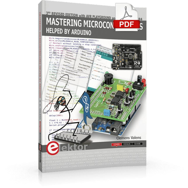
Third, extended and revised edition with AVR Playground and Elektor Uno R4
Arduino boards have become hugely successful. They are simple to use and inexpensive. This book will not only familiarize you with the world of Arduino but it will also teach you how to program microcontrollers in general. In this book theory is put into practice on an Arduino board using the Arduino programming environment.
Some hardware is developed too: a multi-purpose shield to build some of the experiments from the first 10 chapters on; the AVR Playground, a real Arduino-based microcontroller development board for comfortable application development, and the Elektor Uno R4, an Arduino Uno R3 on steroids.
The author, an Elektor Expert, provides the reader with the basic theoretical knowledge necessary to program any microcontroller: inputs and outputs (analog and digital), interrupts, communication busses (RS-232, SPI, I²C, 1-wire, SMBus, etc.), timers, and much more. The programs and sketches presented in the book show how to use various common electronic components: matrix keyboards, displays (LED, alphanumeric and graphic color LCD), motors, sensors (temperature, pressure, humidity, sound, light, and infrared), rotary encoders, piezo buzzers, pushbuttons, relays, etc. This book will be your first book about microcontrollers with a happy ending!
This book is for you if you are a beginner in microcontrollers, an Arduino user (hobbyist, tinkerer, artist, etc.) wishing to deepen your knowledge,an Electronics Graduate under Undergraduate student or a teacher looking for ideas.
Thanks to Arduino the implementation of the presented concepts is simple and fun. Some of the proposed projects are very original:
Money Game
Misophone (a musical fork)
Car GPS Scrambler
Weather Station
DCF77 Decoder
Illegal Time Transmitter
Infrared Remote Manipulator
Annoying Sound Generator
Italian Horn Alarm
Overheating Detector
PID Controller
Data Logger
SVG File Oscilloscope
6-Channel Voltmeter
All projects and code examples in this book have been tried and tested on an Arduino Uno board. They should also work with the Arduino Mega and every other compatible board that exposes the Arduino shield extension connectors.
Please note
For this book, the author has designed a versatile printed circuit board that can be stacked on an Arduino board. The assembly can be used not only to try out many of the projects presented in this book but also allows for new exercises that in turn provide the opportunity to discover new techniques. Also available is a kit of parts including the PCB and all components. With this kit you can build most of the circuits described in the book and more.
Datasheets Active Components Used (.PDF file):
ATmega328 (Arduino Uno)
ATmega2560 (Arduino Mega 2560)
BC547 (bipolar transistor, chapters 7, 8, 9)
BD139 (bipolar power transistor, chapter 10)
BS170 (N-MOS transistor, chapter 8)
DCF77 (receiver module, chapter 9)
DS18B20 (temperature sensor, chapter 10)
DS18S20 (temperature sensor, chapter 10)
HP03S (pressure sensor, chapter 8)
IRF630 (N-MOS power transistor, chapter 7)
IRF9630 (P-MOS power transistor, chapter 7)
LMC6464 (quad op-amp, chapter 7)
MLX90614 (infrared sensor, chapter 10)
SHT11 (humidity sensor, chapter 8)
TS922 (dual op-amp, chapter 9)
TSOP34836 (infrared receiver, chapter 9)
TSOP1736 (infrared receiver, chapter 9)
MPX4115 (analogue pressure sensor, chapter 11)
MCCOG21605B6W-SPTLYI (I²C LCD, chapter 12)
SST25VF016B (SPI EEPROM, chapter 13)
About the author
Clemens Valens, born in the Netherlands, lives in France since 1997. Manager at Elektor Labs and Webmaster of ElektorLabs, in love with electronics, he develops microcontroller systems for fun, and sometimes for his employer too. Polyglot—he is fluent in C, C++, PASCAL, BASIC and several assembler dialects—Clemens spends most of his time on his computer while his wife, their two children and two cats try to attract his attention (only the cats succeed). Visit the author’s website: www.polyvalens.com.Authentic testimony of Hervé M., one of the first readers of the book:'I almost cried with joy when this book made me understand things in only three sentences that seemed previously completely impenetrable.'
Elektor GREEN and GOLD members can download their digital edition here.
Not a member yet? Click here.
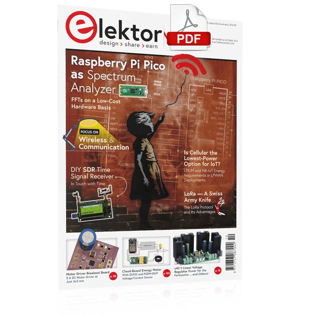
Raspberry Pi Pico as Spectrum AnalyzerFFTs on a Low-Cost Hardware Basis
±40-V Linear Voltage RegulatorAn Alternative Power Supply for the Fortissimo-100 Power Amplifier… and Others!
MCU Wireless Communication Made FlexibleEEPROM Opens Networking Prospects for Wireless MCUs
€5,000 up for grabs!Join the STM32 Wireless Innovation Design Contest
2023: An AI OdysseyGetting Started with ChatGPT’s Code Interpreter
LoRa, a Swiss Army Knife (1)The LoRa Protocol and Its Advantages
Adjustable Current Sink with Integrated Clock GeneratorTest Power Supplies, Voltage Converters and Batteries
Two New Arduino UNO R4 Boards: Minima and WiFi
Logarithmic PotentiometersThey’re Exponential!
Motor Driver Breakout BoardA BoB for a 5 A DC Motor Driver with a 3×3 mm Size
From Life’s ExperienceHazardous Electronics
Is Cellular the Lowest-Power Option for IoT?LTE-M and NB-IoT Energy Requirements in LPWAN Deployments
Wireless Communication in IoT Systems – Using Arduino MKR ModulesThe Right Board for Wi-Fi, LoRa, and Many More Standards
AC Losses in Magnetic ComponentsAvoid Hot Inductors!
Measurement for Optimal Cloud Deployment
Matter Adoption: What does it take to deploy Matter devices?
YARD Stick OneA Sub-1 GHz Wireless Test Tool
Latching RelaysPeculiar Parts, the Series
PIC O’Clock – In Touch with TimeDesigning an SDR Time Signal Receiver
Due Diligence DirectiveBusiness as Usual Will Not Do
Starting Out in Electronics……Voltage Amplification
Infrasound Recorder with the Arduino Pro MiniA Sample Project from Elektor’s “Arduino & Co.” Book
Cloud-Based Energy MeterWith ESP32 Module and PZEM-004T Voltage/Current Sensor
A Bare-Metal Programming Guide (Part 2)Accurate Timing, the UART, and Debugging
Hexadoku
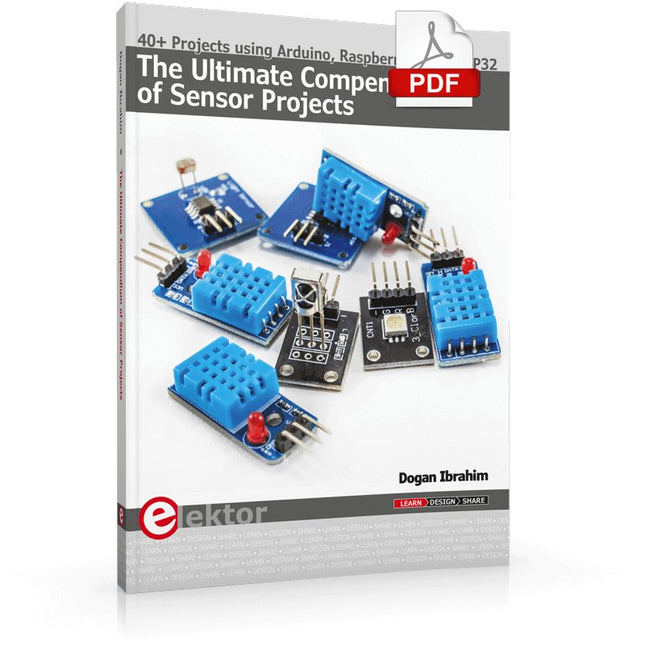
40+ Projects using Arduino, Raspberry Pi and ESP32
This book is about developing projects using the sensor-modules with Arduino Uno, Raspberry Pi and ESP32 microcontroller development systems. More than 40 different sensors types are used in various projects in the book. The book explains in simple terms and with tested and fully working example projects, how to use the sensors in your project. The projects provided in the book include the following:
Changing LED brightness
RGB LEDs
Creating rainbow colours
Magic wand
Silent door alarm
Dark sensor with relay
Secret key
Magic light cup
Decoding commercial IR handsets
Controlling TV channels with IT sensors
Target shooting detector
Shock time duration measurement
Ultrasonic reverse parking
Toggle lights by clapping hands
Playing melody
Measuring magnetic field strength
Joystick musical instrument
Line tracking
Displaying temperature
Temperature ON/OFF control
Mobile phone-based Wi-Fi projects
Mobile phone-based Bluetooth projects
Sending data to the Cloud
The projects have been organized with increasing levels of difficulty. Readers are encouraged to tackle the projects in the order given. A specially prepared sensor kit is available from Elektor. With the help of this hardware, it should be easy and fun to build the projects in this book.
The Siglent SDS1104X-E employs a new generation of SPO (Super Phosphor Oscilloscope) technology that provides excellent signal fidelity and performance. The system noise is also lower than similar products in the industry. It comes with a minimum vertical input range of 500 uV/div, an innovative digital trigger system with high sensitivity and low jitter, and a waveform capture rate of 400,000 frames/sec (sequence mode).
The SDS1104X-E also employs a 256-level intensity grading display function and a color temperature display mode not found in other models in this class. SIGLENT’s latest oscilloscopes offering supports multiple powerful triggering modes including serial bus triggering. Serial decoding is free and includes IIC, SPI, UART, CAN, and LIN. History waveform recording and sequential triggering enable extended waveform recording and analysis. Another powerful addition is the new 1 Mpt FFT math function that gives the SDS1104X-E very high frequency resolution when observing signal spectra.
Features
Intelligent trigger: Edge, Slope, Pulse Width, Window, Runt, Interval, Timeout (Dropout), and Pattern
Free Serial bus triggering and decoding:IIC, SPI, UART, RS232, CAN, and LIN
Video triggers and supports HDTV
Low background noise and 500 μV / div to 10 V / div voltage scales
10 types of one-button shortcuts, supports Auto Setup, Default, Cursors, Measure, Roll, History, Display/Persist, Clear Sweep, Zoom and Print
Segmented acquisition (Sequence) mode, dividing the maximum record length into multiple segments (up to 80,000), according to trigger conditions set by the user, with a very small dead time segment to capture the qualifying event.
History waveform record (History) function, the maximum recorded waveform length is 80,000 frames
Automatic measurement function on 38 parameters, supports Statistics, Gating measurement, Math measurement, History measurement and Ref measurement
1 Mpts FFT
True measurement and math can use all 14 Mpts of memory
Preset key can be customized for user settings or factory “defaults”
Security Erase mode
Highspeed hardware based Pass/ Fail function
Large 7-inch TFT-LCD display with 800 * 480 resolution
Multiple interface types: USB Host, USB Device (USB-TMC), LAN (VXI-11), Pass / Fail, Trigger Out
Supports SCPI remote control commands
Multi-language display and embedded help
Browser control/onboard webpage for software free monitoring (4 channel models only)
Included
1x Siglent SDS1104X-E Oscilloscope
4x 100 MHz probes
1x Guarantee Card
1x Power Cord
1x USB Cable
1x Quick Start Guide
Downloads
Datasheet
Manual
Programming Guide