Search results for "strompi OR 3 OR power OR solution OR for OR single OR board OR computers"
-
Elektor Publishing Nucleo Boards Programming with the STM32CubeIDE
Hands-on in more than 50 projects STM32 Nucleo family of processors are manufactured by STMicroelectronics. These are low-cost ARM microcontroller development boards. This book is about developing projects using the popular STM32CubeIDE software with the Nucleo-L476RG development board. In the early Chapters of the book the architecture of the Nucleo family is briefly described. The book covers many projects using most features of the Nucleo-L476RG development board where the full software listings for the STM32CubeIDE are given for each project together with extensive descriptions. The projects range from simple flashing LEDs to more complex projects using modules, devices, and libraries such as GPIO, ADC, DAC, I²C, SPI, LCD, DMA, analogue inputs, power management, X-CUBE-MEMS1 library, DEBUGGING, and others. In addition, several projects are given using the popular Nucleo Expansion Boards. These Expansion Boards plug on top of the Nucleo development boards and provide sensors, relays, accelerometers, gyroscopes, Wi-Fi, and many others. Using an expansion board together with the X-CUBE-MEMS1 library simplifies the task of project development considerably. All the projects in the book have been tested and are working. The following sub-headings are given for each project: Project Title, Description, Aim, Block Diagram, Circuit Diagram, and Program Listing for the STM32CubeIDE. In this book you will learn about STM32 microcontroller architecture; the Nucleo-L476RG development board in projects using the STM32CubeIDE integrated software development tool; external and internal interrupts and DMA; DEBUG, a program developed using the STM32CubeIDE; the MCU in Sleep, Stop, and in Standby modes; Nucleo Expansion Boards with the Nucleo development boards. What you need a PC with Internet connection and a USB port; STM32CubeIDE software (available at STMicroelectronics website free of charge) the project source files, available from the book’s webpage hosted by Elektor; Nucleo-L476RG development board; simple electronic devices such as LEDs, temperature sensor, I²C and SPI chips, and a few more; Nucleo Expansion Boards (optional).
€ 49,95
Members € 44,96
-
Elektor Digital Computer Vision (EN) PDF
Computer vision is probably the most exciting branch of image processing, and the number of applications in robotics, automation technology and quality control is constantly increasing. Unfortunately entering this research area is, as yet, not simple. Those who are interested must first go through a lot of books, publications and software libraries. With this book, however, the first step is easy. The theoretically founded content is understandable and is supplemented by many practical examples. Source code is provided with the specially developed platform-independent open source library IVT in the programming language C/C++. The use of the IVT is not necessary, but it does make for a much easier entry and allows first developments to be quickly produced. The authorship is made up of research assistants of the chair of Professor Ruediger Dillmann at the Institut für Technische Informatik (ITEC), Universitaet Karlsruhe (TH). Having gained extensive experience in image processing in many research and industrial projects, they are now passing this knowledge on. Among other subjects, the following are dealt with in the fundamentals section of the book: Lighting, optics, camera technology, transfer standards, camera calibration, image enhancement, segmentation, filters, correlation and stereo vision. The practical section provides the efficient implementation of the algorithms, followed by many interesting applications such as interior surveillance, bar code scanning, object recognition, 3-D scanning, 3-D tracking, a stereo camera system and much more.
€ 19,95
Members € 15,96
-

NXP Semiconductors NXP FRDM-MCXN947 Development Board
The FRDM-MCXN947 is a compact and versatile development board designed for rapid prototyping with MCX N94 and N54 microcontrollers. It features industry-standard headers for easy access to the MCU's I/Os, integrated open-standard serial interfaces, external flash memory, and an onboard MCU-Link debugger. Specifications Microcontroller MCX-N947 Dual Arm Cortex-M33 cores @ 150 MHz each with optimized performance efficiency, up to 2 MB dual-bank flash with optional full ECC RAM, External flash Accelerators: Neural Processing Unit, PowerQuad, Smart DMA, etc. Memory Expansion *DNP Micro SD card socket Connectivity Ethernet Phy and connector HS USB-C connectors SPI/I²C/UART connector (PMOD/mikroBUS, DNP) WiFi connector (PMOD/mikroBUS, DNP) CAN-FD transceiver Debug On-board MCU-Link debugger with CMSIS-DAP JTAG/SWD connector Sensor P3T1755 I³C/I²C Temp Sensor, Touch Pad Expansion Options Arduino Header (with FRDM expansion rows) FRDM Header FlexIO/LCD Header SmartDMA/Camera Header Pmod *DNP mikroBUS User Interface RGB user LED, plus Reset, ISP, Wakeup buttons Included 1x FRDM-MCXN947 Development Board 1x USB-C Cable 1x Quick Start Guide Downloads Datasheet Block diagram
€ 29,95€ 19,95
Members identical
-
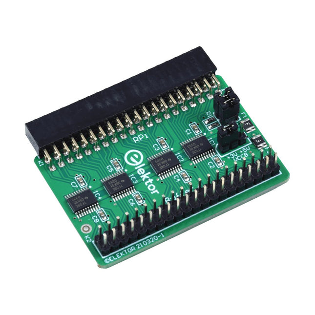
Elektor Labs Elektor Raspberry Pi Buffer Board
When you experiment with the Raspberry Pi on a regular basis and you connect a variety of external hardware to the GPIO port via the header you may well have caused some damage in the past. The Elektor Raspberry Pi Buffer Board is there to prevent this! The board is compatible with Raspberry Pi Zero, Zero 2 (W), 3, 4, 5, 400 and 500. All 26 GPIOs are buffered with bi-directional voltage translators to protect the Raspberry Pi when experimenting with new circuits. The PCB is intended to be inserted in the back of Raspberry Pi 400/500. The connector to connect to the Raspberry Pi is a right angled 40-way receptacle (2x20). The PCB is only a fraction wider. A 40-way flat cable with appropriate 2x20 headers can be connected to the buffer output header to experiment for instance with a circuit on a breadboard or PCB. The circuit uses 4x TXS0108E ICs by Texas Instruments. The PCB can also be put upright on a Raspberry Pi. Downloads Schematics Layout
€ 34,95€ 29,95
Members identical
-

Pinecone Pinecone BL602 Evaluation Board
Features Build in USB to Serial interface Build-in PCB antenna Powered by Pineseed BL602 SoC using Pinenut model: 12S stamp 2 MB Flash USB-C connection Suitable to breadboard BIY project On board three color LEDs output Dimensions: 25.4 x 44.0 mm Note: USB cable is not included.
€ 8,95€ 3,50
Members identical
-

Elektor Digital Programming with STM32 Nucleo Boards (E-book)
STM32 Nucleo family of processors are manufactured by STMicroelectronics. These are low-cost ARM microcontroller development boards. This book is about developing projects using the popular Nucleo development board. In the early chapters of the book, the architecture of the Nucleo family is briefly described. Software development tools that can be used with the Nucleo boards such as the Mbed, Keil MDK, TrueSTUDIO, and the System Workbench are described briefly in later Chapters. The book covers many projects using most features of the STM32 Nucleo development boards where the full software listings for Mbed and System Workbench are given for every project. The projects range from simple flashing LEDs to more complex projects using modules and devices such as GPIO, ADC, DAC, I²C, LCD, analog inputs and others. In addition, several projects are given using the Nucleo Expansion Boards, including popular expansion boards such as solid-state relay, MEMS and environmental sensors, DC motor driver, Wi-Fi, and stepper motor driver. These Expansion Boards plug on top of the Nucleo development boards and simplify the task of project development considerably. Features of this book Learn the architecture of the STM32 microcontrollers Learn how to use the Nucleo development board in projects using Mbed and System Workbench Toolchains Learn how to use the Nucleo Expansion Boards with the Nucleo development boards Update The Mbed compiler has been replaced with two software packages: The Mbed Studio and Keil Studio Cloud. Both of these software packages are free of charge and are available on the Internet. If you need assistance using the Keil Studio Cloud, please download the Guide below.
€ 34,95
Members € 27,96
-
Elektor Publishing H0W2: Get Started with the MAX78000FTHR Development Board
Build your own AI microcontroller applications from scratch The MAX78000FTHR from Maxim Integrated is a small development board based on the MAX78000 MCU. The main usage of this board is in artificial intelligence applications (AI) which generally require large amounts of processing power and memory. It marries an Arm Cortex-M4 processor with a floating-point unit (FPU), convolutional neural network (CNN) accelerator, and RISC-V core into a single device. It is designed for ultra-low power consumption, making it ideal for many portable AI-based applications. This book is project-based and aims to teach the basic features of the MAX78000FTHR. It demonstrates how it can be used in various classical and AI-based projects. Each project is described in detail and complete program listings are provided. Readers should be able to use the projects as they are, or modify them to suit their applications. This book covers the following features of the MAX78000FTHR microcontroller development board: Onboard LEDs and buttons External LEDs and buttons Using analog-to-digital converters I²C projects SPI projects UART projects External interrupts and timer interrupts Using the onboard microphone Using the onboard camera Convolutional Neural Network
€ 39,95
Members € 35,96
-
Elektor Publishing Wireless Power Design
From Theory to Practical Applications in Wireless Energy Transfer and Harvesting Wireless power transmission has gained significant global interest, particularly with the rise of electric vehicles and the Internet of Things (IoT). It’s a technology that allows the transfer of electricity without physical connections, offering solutions for everything from powering small devices over short distances to long-range energy transmission for more complex systems. Wireless Power Design provides a balanced mix of theoretical knowledge and practical insights, helping you explore the potential of wireless energy transfer and harvesting technologies. The book presents a series of hands-on projects that cover various aspects of wireless power systems, each accompanied by detailed explanations and parameter listings. The following five projects guide you through key areas of wireless power: Project 1: Wireless Powering of Advanced IoT Devices Project 2: Wireless Powered Devices on the Frontline – The Future and Challenges Project 3: Wireless Powering of Devices Using Inductive Technology Project 4: Wireless Power Transmission for IoT Devices Project 5: Charging Robot Crawler Inside the Pipeline These projects explore different aspects of wireless power, from inductive charging to wireless energy transmission, offering practical solutions for real-world applications. The book includes projects that use simulation tools like CST Microwave Studio and Keysight ADS for design and analysis, with a focus on practical design considerations and real-world implementation techniques.
€ 39,95
Members € 35,96
-

Würth Abc of Power Modules (E-book)
Functionality, structure and handling of a power module For readers with first steps in power management the “Abc of Power Modules” contains the basic principles necessary for the selection and use of a power module. The book describes the technical relationships and parameters related to power modules and the basis for calculation and measurement techniques. Contents Basics This chapter describes the need of a DC/DC voltage converter and its basic functionality. Furthermore, various possibilities for realizing a voltage regulator are presented and the essential advantages of a power module are mentioned. Circuit topologies Circuit concepts, buck and boost topologies very frequently used with power modules are explained in detail and further circuit topologies are introduced. Technology, construction and regulation technology The mechanical construction of a power module is presented, which has a significant influence on EMC and thermal performance. Furthermore, control methods are explained and circuit design tips are provided in this chapter. Measuring methods Meaningful measurement results are absolutely necessary to assess a power module. The relevant measurement points and measurement methods are described in this chapter. Handling The aspects of storage and handling of power modules are explained, as well as their manufacturing and soldering processes. Selection of a power modules Important parameters and criteria for the optimal selection of a power module are presented in this section.
€ 8,99
Members € 7,19
-

Siglent Siglent SPD3303X 3-ch DC Power Supply (220 W)
SPD3000X Series Linear Programmable DC Power Supply has a 4.3 inches TFT LCD display, Supports Programmability and Real Time Wave Display, bringing a new experience to users. It has three isolated outputs: two adjustable channels and one selectable channel from 2.5V, 3.3V, and 5V. It also has output short and overload protect function, and can be used in production and development. Features 3 independent controlled and isolated output, 32V/3.2A×2, 2.5V/3.3V/5V/3.2A×1, total 220W. 5 digits Voltage, 4 digits Current Display, Minimum Resolution: 1mV/1mA. Supports panel timing output functions. 4.3 inch true color TFT LCD 480x272 pixel display. 3 kinds of output modes: independent, series, parallel. 100V/120V/220V/230V compatible design to meet the needs of different power grids. Intelligent temperature-controlled fan, effectively reducing noise. Clear graphical interface, with the waveform display function Internal 5 groups of system parameter save/recall, supports data storage space expansion. Provides PC software: Easypower, supports SCPI, LabVIEW driver. High-resolution and high-precision output The highest resolution of 1mV/1mA, provides excellent setting and read back accuracy. This ensures accurate output even with very with small changes in voltage or current. This is impossible for a low resolution power supply. Series/parallel/independent mode function Series and parallel function allows two channels combined into one output with more power output capability, extending the application range. Each of 3 channels power can be turned on or off independently and also can be turned all on or all off. Panel displays the timing output Through the panel operation, 5 groups of timing settings and output control can be displayed, which provides users a simple power programming function. Also a connection can be made with Siglent’s EasyPower PC software providing a full range of communication and control requirements. Save/Recall setting parameters SPD3000X series programmable power supply can save or recall 5 groups of setting parameter in internal storage, also supports external storage expansion. You can easily obtain the settings you needed.
€ 600,50
-

Rigol Rigol DP832 3-ch DC Power Supply (0-30 V, 0-3 A, 195 W)
Specifications Channels: 3 Total Power: 195 Watts Max. Voltage: 30 Volts Max. Current: 3 Amps Low ripple and noise: <350 μVrms/2 mVpp Excellent linear regulation rate and load regulation rate Fast transient response time: <50 μs Some channels are isolated Standard OVP/OCP/OTP protection functions Standard timing output Built-in V,A,W measurements and waveform display Independent control for each channel 3.5 inch TFT display Included 1x Rigol DP832 DC Power Supply 1x Power cord 1x USB cable
€ 427,21
-

Elektor Digital H0W2: Get Started with the MAX78000FTHR Development Board (E-book)
Build your own AI microcontroller applications from scratch The MAX78000FTHR from Maxim Integrated is a small development board based on the MAX78000 MCU. The main usage of this board is in artificial intelligence applications (AI) which generally require large amounts of processing power and memory. It marries an Arm Cortex-M4 processor with a floating-point unit (FPU), convolutional neural network (CNN) accelerator, and RISC-V core into a single device. It is designed for ultra-low power consumption, making it ideal for many portable AI-based applications. This book is project-based and aims to teach the basic features of the MAX78000FTHR. It demonstrates how it can be used in various classical and AI-based projects. Each project is described in detail and complete program listings are provided. Readers should be able to use the projects as they are, or modify them to suit their applications. This book covers the following features of the MAX78000FTHR microcontroller development board: Onboard LEDs and buttons External LEDs and buttons Using analog-to-digital converters I²C projects SPI projects UART projects External interrupts and timer interrupts Using the onboard microphone Using the onboard camera Convolutional Neural Network
€ 32,95
Members € 26,36


