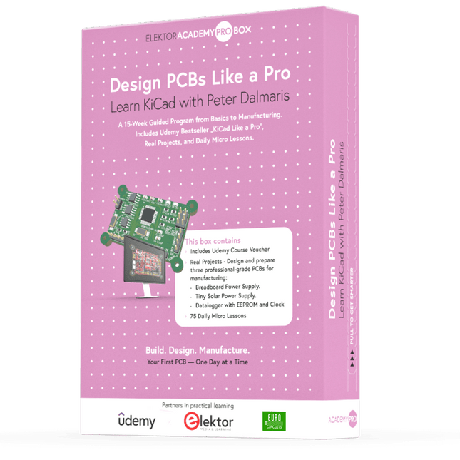
Learn KiCad with Peter Dalmaris
The Academy Pro Box "Design PCBs like a Pro" offers a complete, structured training programme in PCB design, combining online learning with practical application. Based on Peter Dalmaris’ KiCad course, the 15-week programme integrates video lessons, printed materials (2 books), and hands-on projects to ensure participants not only understand the theory but also develop the skills to apply it in practice.
Unlike standard courses, the Academy Pro Box provides a guided learning path with weekly milestones and physical components to design, test, and produce working PCBs. This approach supports a deeper learning experience and better knowledge retention.
The box is ideal for engineers, students, and professionals who want to develop practical PCB design expertise using open-source tools. With the added option to have their final project manufactured, participants complete the programme with real results – ready for use, testing, or further development.
Learn by doing
Build skills. Design real boards. Generate Gerbers. Place your first order. This isn’t just a course – it’s a complete project journey from idea to product.
You’ll walk away with:
Working knowledge of KiCad’s tools
Confidence designing your own PCBs
A fully manufacturable circuit board – made by you
What's inside the Box (Course)?
Both volumes of "KiCad Like a Pro" (valued at €105)
Vol 1: Fundamentals and Projects
Vol 2: Advanced Projects and Recipes
Coupon code to join the bestselling KiCad 9 online course by Peter Dalmaris on Udemy, featuring 20+ hours of video training. You'll complete three full design projects:
Breadboard Power Supply
Tiny Solar Power Supply
Datalogger with EEPROM and Clock
Voucher from Eurocircuits for the production of PCBs (worth €85 excl. VAT)
Learning Material (of this Box/Course)
15-Week Learning Program
▶ Click here to open
Week 1: Setup, Fundamentals, and First Steps in PCB Design
Week 2: Starting Your First PCB Project – Schematic Capture
Week 3: PCB Layout – From Netlist to Board Design
Week 4: Design Principles, Libraries, and Workflow
Week 5: Your First Real-World PCB Project
Week 6: Custom Libraries – Symbols, Footprints, and Workflow
Week 7: Advanced Tools – Net Classes, Rules, Zones, Routing
Week 8: Manufacturing Files, BOMs, and PCB Ordering
Week 9: Advanced Finishing Techniques – Graphics, Refinement, and Production Quality
Week 10: Tiny Solar Power Supply – From Schematic to Layout
Week 11: Tiny Solar Power Supply – PCB Layout and Production Prep
Week 12: ESP32 Clone Project – Schematic Design and Layout Prep
Week 13: ESP32 Clone – PCB Layout and Manufacturing Prep
Week 14: Final Improvements and Advanced Features
Week 15: Productivity Tools, Simulation, and Automation
KiCad Course with 18 Lessons on Udemy (by Peter Dalmaris)
▶ Click here to open
Introduction
Getting started with PCB design
Getting started with KiCad
Project: A hands-on tour of KiCad (Schematic Design)
Project: A hands-on tour of KiCad (Layout)
Design principles and PCB terms
Design workflow and considerations
Fundamental KiCad how-to: Symbols and Eeschema
Fundamental KiCad how-to: Footprints and Pcbnew
Project: Design a simple breadboard power supply PCB
Project: Tiny Solar Power Supply
Project: MCU datalogger with build-in 512K EEPROM and clock
Recipes
KiCad 9 new features and improvements
Legacy (from previous versions of KiCad)
KiCad 7 update (Legacy)
(Legacy) Gettings started with KiCad
Bonus lecture
About the Author
Dr. Peter Dalmaris, PhD is an educator, an electrical engineer and Maker. Creator of online video courses on DIY electronics and author of several technical books. As a Chief Tech Explorer since 2013 at Tech Explorations, the company he founded in Sydney, Australia, Peter's mission is to explore technology and help educate the world.
What is Elektor Academy Pro?
Elektor Academy Pro delivers specialized learning solutions designed for professionals, engineering teams, and technical experts in the electronics and embedded systems industry. It enables individuals and organizations to expand their practical knowledge, enhance their skills, and stay ahead of the curve through high-quality resources and hands-on training tools.
From real-world projects and expert-led courses to in-depth technical insights, Elektor empowers engineers to tackle today’s electronics and embedded systems challenges. Our educational offerings include Academy Books, Pro Boxes, Webinars, Conferences, and industry-focused B2B magazines – all created with professional development in mind.
Whether you're an engineer, R&D specialist, or technical decision-maker, Elektor Academy Pro bridges the gap between theory and practice, helping you master emerging technologies and drive innovation within your organization.
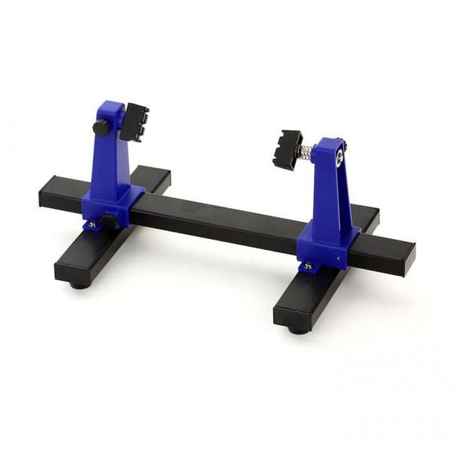
This adjustable circuit board holder is ideal for clamping PCB for soldering, desoldering or rework.
Features
2 adjustable grips on a retractable stand to accommodate various board sizes.
The adjustable clamps allow the PCB to rotate 360 degrees and stay set in any position.
The base of this rigid metal stand features four rubber feet to ensure stability.
Specifications
Product size
30 x 16.5 x 12.5 cm
Max. holding size
20 x 14 cm
Weight
450 g
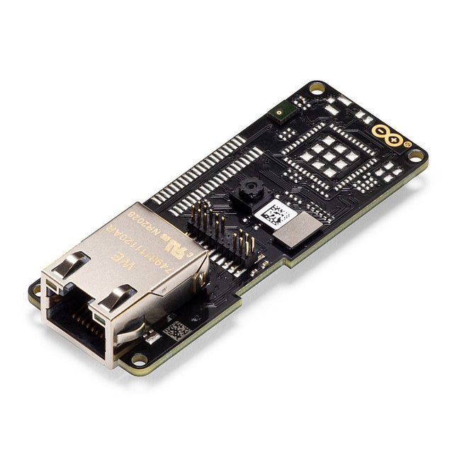
The Arduino Pro Portenta Vision Shield brings industry-rated features to your Portenta. This hardware add-on will let you run embedded computer vision applications, connect wirelessly or via Ethernet to the Arduino Cloud or your own infrastructure, and activate your system upon the detection of sound events.
Features
324x324 pixels camera sensor: use one of the cores in Portenta to run image recognition algorithms using the OpenMV for Arduino editor
100 Mbps Ethernet connector: get your Portenta H7 connected to the wired Internet
2 onboard microphones for directional sound detection: capture and analyse sound in real-time
JTAG connector: perform low-level debugging of your Portenta board or special firmware updates using an external programmer
SD-Card connector: store your captured data in the card, or read configuration files
The Vision Shield has been designed to fit on top of the Arduino Portenta family. The Portenta boards feature multicore 32-bit ARM Cortex processors running at hundreds of megahertz, with megabytes of program memory and RAM. Portenta boards come with WiFi and Bluetooth.
Embedded Computer Vision Made Easy
Arduino has teamed up with OpenMV to offer you a free license to the OpenMV IDE, an easy way into computer vision using MicroPython as a programming paradigm. Download the OpenMV for Arduino Editor from our professional tutorials site and browse through the examples we have prepared for you inside the OpenMV IDE. Companies across the whole world are already building their commercial products based on this simple-yet-powerful approach to detect, filter, and classify images, QR codes, and others.
Debugging With Professional Tools
Connect your Portenta H7 to a professional debugger through the JTAG connector. Use professional software tools like the ones from Lauterbach or Segger on top of your board to debug your code step by step. The Vision Shield exposes the required pins for you to plug in your external JTAG.
Camera
Himax HM-01B0 camera module
Resolution
320 x 320 active pixel resolution with support for QVGA
Image sensor
High sensitivity 3.6μ BrightSense pixel technology
Microphone
2 x MP34DT05
Length
66 mm
Width
25 mm
Weight
11 gr
For more information, check out the tutorials provided by Arduino here.
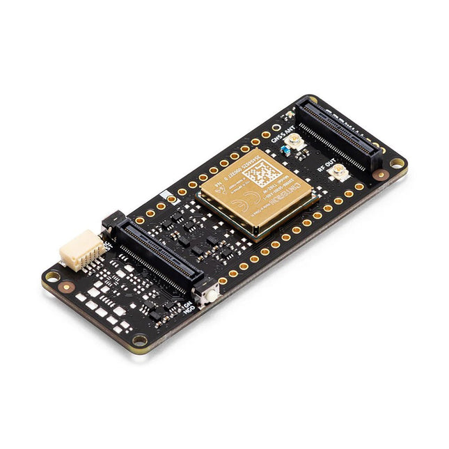
The Arduino Pro Portenta Cat. M1/NB IoT GNSS Shield allows you to enhance the connectivity features of your Portenta H7 applications. The shield leverages a Cinterion TX62 wireless module by Thales, designed for highly efficient, low-power IoT applications to deliver optimized bandwidth and performance.
The Portenta Cat. M1/NB IoT GNSS Shield combines with the strong edge computing power of the Portenta H7 to enable the development of asset tracking and remote monitoring applications in industrial settings, as well as in agriculture, public utilities and smart cities. The shield offers cellular connectivity to both Cat. M1 and NB-IoT networks with the option to use eSIM technology. Easily track your valuables – across the city or worldwide – with your choice of GPS, GLONASS, Galileo or BeiDou.
Features
Change connectivity capabilities without changing the board
Add NB-IoT, CAT. M1 and positioning to any Portenta product
Possibility to create a small multiprotocol router (WiFi - BT + NB-IoT/CAT. M1)
Greatly reduce communication bandwidth requirements in IoT applications
Low-power module
Compatible also with MKR boards
Remote Monitoring
Industrial and agricultural companies can leverage the Portenta Cat. M1/NB IoT GNSS Shield to remotely monitor gas detectors, optical sensors, machinery alarm systems, biological bug traps and more.
Technology providers providing smart city solutions can compound the power and reliability of the Portenta H7 with the Portenta Cat. M1/NB IoT GNSS Shield, to connect data and automate actions for a truly optimized use of resources and enhanced user experience.
Asset Monitoring
Add monitoring capabilities to any asset by combining the performance and edge computing features of the Portenta family boards. The Portenta Cat. M1/NB IoT GNSS Shield is ideal to monitor valuable goods and also for monitoring industrial machinery and equipment.
Specifications
Connectivity
Cinterion TX62 wireless module; NB-IoT - LTE CAT.M1; 3GPP Rel.14 Compliant Protocol LTE Cat. M1/NB1/NB2; UMTS BANDS: 1 / 2 / 3 / 4 / 5 / 8 / 12(17) / 13 / 18 / 19 / 20 / 25 / 26 / 27 / 28 / 66 / 71 / 85; LTE Cat.M1 DL: max. 300 kbps, UL: max. 1.1 Mbps; LTE Cat.NB1 DL: max. 27 kbps, UL: max. 63 kbps; LTE Cat.NB2 DL: max. 124 kbps, UL: max. 158 kbps
Short messaging service (SMS)
Point-to-point mobile terminated (MT) and mobile originated (MO) Text Mode; Protocol Data Unit (PDU) Mode
Localization support
GNSS capability (GPS/BeiDou/Galileo/GLONASS)
Other
Embedded IPv4 and IPv6 TCP/IP stack access; Internet Services: TCP server/client, UDP client, DNS, Ping, HTTP client, FTP client, MQTT client Secure Connection with TLS/DTLS Secure boot
Dimensions
66 x 25.4 mm
Operating temperature
-40° C to +85° C (-104° F to 185°F)
Downloads
Datasheet
Schematics
Make your project dreams come true: an odometer for the hamster wheel, a fully automatic control of your ant farm with web interface, or the Sandwich-O-Mat – a machine that toasts and grills sandwiches of your choice.
With the Arduino and the DIY or Maker movement, not only did entry into microcontroller programming become child's play, but a second development also took place: Resourceful developers brought small boards – so-called shields or modules – to the market, which greatly simplified the use of additional hardware. The small modules contain all the important electronic parts to be connected to the microcontroller with a few plug-in cables, eliminating the need for a fiddly and time-consuming assembly on the plug-in board. In addition, it is also possible to handle tiny components that do not have any connecting legs (so-called SMDs).
Projects Discussed
Arduino seeks connection
BMP and introduction to libraries, I²C
Learn I/O basics with the multi-purpose shield
I²C LCD adapter and DOT matrix displays
LCD keypad shield
Level converter
W5100: Internet connection
I/O expansion shield
Relays and solid-state relays
The multi-function shield: A universal control unit
Connecting an SD card reader via SPI
Keys and 7-segment displays
16-bit ADC
MCP4725 DAC
16-way PWM servo driver
MP3 player
GPS data logger using an SD card
Touch sensor
Joystick
SHT31: Temperature and humidity
VEML6070 UV-A sensor
VL53L0X time-of-flight
Ultrasonic distance meter
MAX7219-based LED DOT matrix display
DS3231 RTC
Port expander MCP23017
433 MHz radio
MPU-650 gyroscope
ADXL345 accelerometer
WS2812 RGB LEDs
Power supply
MQ-xx gas sensors
CO2 gas sensor
ACS712 current sensor
INA219 current sensor
L298 motor driver
MFRC522 RFID
28BYJ-48 stepper motor
TMC2209 silent step stick
X9C10x digital potentiometer
ST7735 in a color TFT display
e-Paper display
Bluetooth
Geiger counter
SIM800L GSM module
I²C multiplexer
Controller Area Network
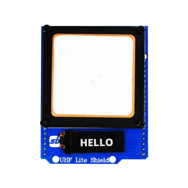
Designed with cutting-edge technology, this shield brings the power of Ultra High Frequency (UHF) RFID to your fingertips.
With the Ardi UHF Shield, you can effortlessly read up to an impressive 50 tags per second, allowing for fast and efficient data collection. The shield features an onboard UHF antenna, ensuring reliable and accurate tag detection even in challenging environments.
Equipped with a high-performance 0.91" OLED display, the Ardi UHF Shield provides clear and concise visual feedback, making it easy to monitor and interact with the RFID readings. Whether you're tracking inventory, managing access control, or implementing a smart attendance system, this shield has you covered.
With a remarkable 1-meter reading distance, the Ardi UHF Shield offers an extended range for capturing RFID data. Say goodbye to the limitations of proximity-based RFID systems and embrace the flexibility and convenience of a wider reading range.
The shield provides read-write capabilities, allowing you to not only retrieve information from RFID tags but also update or modify data as needed. This versatility opens up a world of possibilities for advanced applications and custom solutions.
Features
Onboard High-performance UHF RFID reader module
24 hours x 365 days’ work normally
0.91” OLED display for visual interaction with shield
Multi-tone Buzzer onboard for Audio alerts
Shield compatible with both 3.3 V and 5 V MCU
Mounts directly onto ArdiPi, Ardi32 or other Arduino compatible boards
Specifications
OLED resolution 128x32 pixels
I²C Interface for OLED
UHF Frequency Range (EU/UK): 865.1-867.9 MHz
UHF Module Type: Read/Write
Protocols Supported: EPCglobal UHF Class 1 Gen 2 / ISO 18000-6C
Reading Distance: 1 meters
Can identify over 50 tags simultaneously
Communication interface: TTL UART Interface for UHF
Communication baud rate: 115200 bps (default and recommend) – 38400 bps
Operation current: 180 mA @ 3.5 V (26 dBm Output, 25°C), 110 mA @ 3.5 V (18 dBm Output, 25°C)
Working humidity <95% (+25°C)
Heat-dissipating method Air cooling(no need out install cooling fin)
Tags storage capacity: 200 pcs tags @ 96 bit EPC
Output power: 18-26 dBm
Output power accuracy: +/-1 dB
Tags RSSI support
Now you can connect your Arduino boards with the official Arduino USB cable. Through a USB-C to USB-C with a USB-A adapter connection, this data USB cable can easily connect your Arduino boards with your chosen programming device. The Arduino USB cable has a nylon braided jacket in the typical Arduino colors white and teal. The connectors have an aluminum shell that protects your cable from harm at the same time as looking cool. Length: 100 cm Aluminium shell with logo Nylon braided jacket white and teal
The SEQURE HT140 is a highly versatile 2-in-1 soldering tool that combines the functionality of hot tweezers and a soldering iron. It is specifically engineered for precise SMD soldering and desoldering tasks.
With independent control for single-sided heating, it operates as a traditional soldering iron when fitted with a standard tip. When configured for dual-sided heating, it transforms into hot tweezers – perfect for the efficient and accurate removal of SMD components.
Features
Working Temperature: 50-500°C (122-932°F)
Supports multiple power inputs: PD 3.1/3.0/2.0, QC 3.0/2.0, (5-28 V DC), LiPo batteries, and power adapters.
The HT140 combines hot tweezers and a soldering iron, with independent single- or dual-sided heating. Use it as a soldering iron with a tip, or as hot tweezers for easy SMD desoldering.
Voltage and current can be adjusted based on the power source.
Features dual temperature control, presets, quick temperature increase, and fine-tuning.
128 x 32 OLED screen with adjustable brightness, and orientation. Switchable °C/°F.
High-precision heating element with ±1% accuracy. Melts solder in just 2 seconds.
Smart standby, sleep, and wake-up functions extend tip lifespan and boost efficiency.
Supports temperature calibration and compensation for precise work.
Includes a 1.5 m heat-resistant PD 150 W silicone cable and a sturdy all-metal HT Station.
Swappable tips and adjustable angles for various SMD soldering tasks.
Specifications
Working Voltage
5-28 V DC
Maximum Power
140 W
Working Temperature
50-500°C (122-932°F)
Tin Melting Time
2s
Interface Type
USB-C, DC5525
Power Supply
PD 3.1/3.0/2.0, QC 3.0/2.0, 28 V DC max
Display
128 x 32 OLED
Firmware Upgrade
Yes
Menu Languages
English, Russian, Chinese
Dimensions
160 x 27 x 17.5 mm
Weight
50 g
Included
1x SEQURE HT140 Host
2x HT140-IS Tapered Curved Desoldering Tips
1x HT Station
1x Accessory Package
1x Storage Bag
1x 65 W PD Power Supply (EU, UK & US)
1x 24 W PD Silicone Wire (1.5 m)
1x GND Wire Accessory Kit (1.8 m)
,
by Clemens Valens
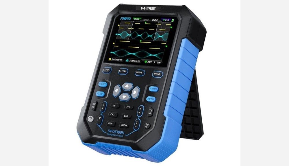
FNIRSI DPOX180H 2-in-1 Digital Phosphor Oscilloscope (Review)
Oscilloscopes sure have made a lot of progress over the past two decades. Twenty years ago, I still used my single-beam analog 20 MHz CRT oscilloscope...
,
by Sebastian Westerhold
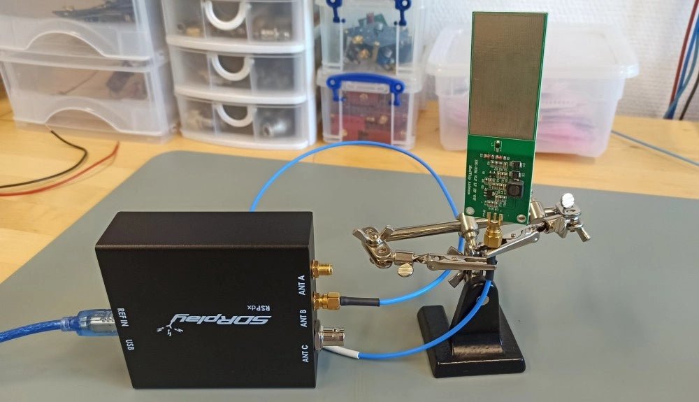
The SDRplay RSPdx SDR Receiver Features Frequency Range of 1 kHz up to 2 GHz (Review)
The SDRplay RSPdx is a 14-bit single-tuner receiver with continuous coverage from 1 kHz up to 2GHz. Three input connectors, an ample array of software...