Build Your Own Vintage Radio Broadcaster
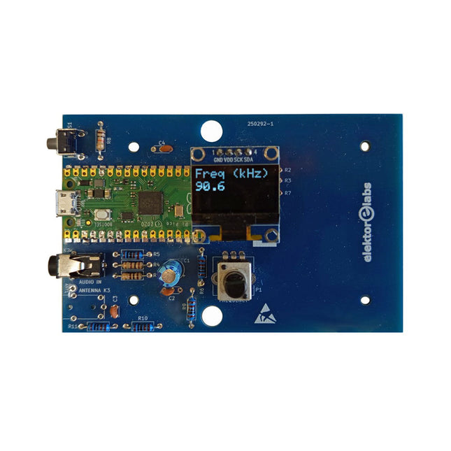
The Elektor AM Transmitter Kit allows streaming audio to vintage AM radio receivers. Based on a Raspberry Pi Pico microcontroller module, the AM Transmitter can transmit on 32 frequencies in the AM band, from 500 kHz up to 1.6 MHz in 32 steps of approx. 35 kHz.
The frequency is selected with a potentiometer and shown on a 0.96" OLED display. A pushbutton allows toggles the transmitting mode between On and Off. The range of the transmitter depends on the antenna. The onboard antenna provides a range of a few centimeters, requiring the AM Transmitter to be placed close to or inside the radio. An external loop antenna (not included) can be connected to increase the range.
The Elektor AM Transmitter Kit comes as a kit of parts that you must solder to the board yourself.
Features
The board is compatible with a Hammond 1593N enclosure (not included).A 5 VDC power supply with micro-USB connector (e.g., an old phone charger) is needed to power the kit (not included). Current consumption is 100 mA.
The Arduino software (requiring Earle Philhower’s RP2040 Boards Package) for the Elektor AM Transmitter Kit plus more information is available at the Elektor Labs page of this project.
Component List
Resistors
R1, R4 = 100 Ω
R2, R3, R8 = 10 kΩ
R5, R6, R9, R10, R11 = 1 kΩ
R7 = optional (not included)
P1 = potentiometer 100 kΩ, linear
Capacitors
C1 = 22 µF 16V
C2, C4 = 10 nF
C3 = 150 pF
Miscellaneous
K1 = 4×1 pin socket
K2, K3 = 3.5 mm socket
Raspberry Pi Pico
pushbutton, angle mount
0.96" monochrome I²C OLED display
PCB 150292-1
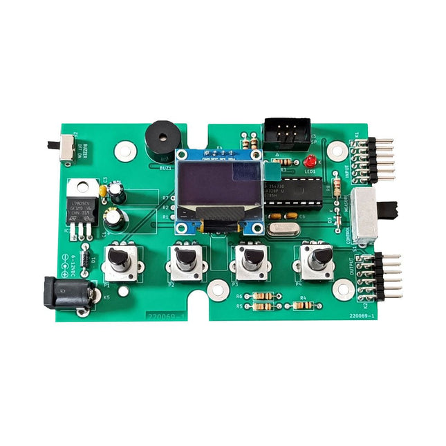
The Elektor Super Servo Tester can control servos and measure servo signals. It can test up to four servo channels at the same time.
The Super Servo Tester comes as a kit. All the parts required to assemble the Super Servo Tester are included in the kit. Assembling the kit requires basic soldering skills. The microcontroller is already programmed.
The Super Servo Tester features two operating modes: Control/Manual and Measure/Inputs.
In Control/Manual mode the Super Servo Tester generates control signals on its outputs for up to four servos or for the flight controller or ESC. The signals are controlled by the four potentiometers.
In Measure/Inputs the Super Servo Tester measures the servo signals connected to its inputs. These signals may come from for instance an ESC, a flight controller, or the receiver or another device. The signals are also routed to the outputs to control the servos or the flight controller or ESC. The results are shown on the display.
Specifications
Operating modes
Control/Manual & Measure/Inputs
Channels
3
Servo signal inputs
4
Servo signal outputs
4
Alarm
Buzzer & LED
Display
0.96' OLED (128 x 32 pixels)
Input voltage on K5
7-12 VDC
Input voltage on K1
5-7.5 VDC
Input current
30 mA (9 VDC on K5, nothing connected to K1 and K2)
Dimensions
113 x 66 x 25 mm
Weight
60 g
Included
Resistors (0.25 W)
R1, R3
1 kΩ, 5%
R2, R4, R5, R6, R7, R9, R10
10 kΩ, 5%
R8
22 Ω, 5%
P1, P2, P3, P4
10 kΩ, lin/B, vertical potentiometer
Capacitors
C1
100 µF 16 V
C2
10 µF 25 V
C3, C4, C7
100 nF
C5, C6
22 pF
Semiconductors
D1
1N5817
D2
LM385Z-2.5
D3
BZX79-C5V1
IC1
7805
IC2
ATmega328P-PU, programmed
LED1
LED, 3 mm, red
T1
2N7000
Miscellaneous
BUZ1
Piezo buzzer with oscillator
K1, K2
2-row, 12-way pinheader, 90°
K5
Barrel jack
K4
1-row, 4-way pin socket
K3
2-row, 6-way boxed pinheader
S1
Slide switch DPDT
S2
Slide switch SPDT
X1
Crystal, 16 MHz
28-way DIP socket for IC2
Elektor PCB
OLED display, 0.96', 128 x 32 pixels, 4-pin I²C interface
Links
Elektor Magazine
Elektor Labs
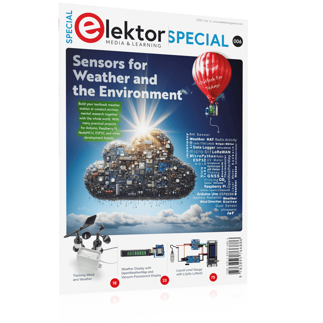
Build your textbook weather station or conduct environmental research together with the whole world. With many practical projects for Arduino, Raspberry Pi, NodeMCU, ESP32, and other development boards.
Weather stations have enjoyed great popularity for decades. Every current and even every long discontinued electronics magazine has regularly featured articles on building your own weather station. Over the years, they have become increasingly sophisticated and can now be fully integrated into an automated home — although this often requires loyalty to an (expensive) brand manufacturer across all components.
With your own weather and environmental data, you can keep up and measure things that no commercial station can. It’s also fun: expand your knowledge of electronics, current microcontroller development boards and programming languages in a fun and meaningful way. For less than 10 euros you can get started and record your first environmental data — with time and growing interest, you will continue to expand your system.
In this Edition
Which Microcontroller Fits My Project?
The Right Development Environment
Tracking Wind and Weather
Weather Display with OpenWeatherMap and Vacuum Fluorescent Display
Volatile Organic Compounds in the Air We Breathe
Working with MQ Sensors: Measuring Carbon Monoxide — Odorless but Toxic
CO2 Traffic Light with ThingSpeak IoT Connection
An Automatic Plant Watering System
Good Indoor Climate: Temperature and Humidity are Important criteria
Classy Thermometer with Vintage Tube Technology
Nostalgic Weather House for the Whole Family
Measuring Air Pressure and Temperature Accurately
Sunburn Warning Device
DIY Sensor for Sunshine Duration
Simple Smartphone Says: Fog or Clear View?
Identifying Earthquakes
Liquid Level Measurement for Vessels and Reservoirs
Water pH Value Measurement
Detecting Radioactive Radiation
GPS: Sensor Location Service Across the Globe
Saving and Timestamping Log Files on SD Cards
LoRaWAN, The Things Network, and ThingSpeak
Operating a LoRaWAN Gateway for TTN
Defying "Wind and Weather"
Mega Display with Weather Forecasz
Build your textbook weather station or conduct environmental research together with the whole world. With many practical projects for Arduino, Raspberry Pi, NodeMCU, ESP32, and other development boards.
Weather stations have enjoyed great popularity for decades. Every current and even every long discontinued electronics magazine has regularly featured articles on building your own weather station. Over the years, they have become increasingly sophisticated and can now be fully integrated into an automated home — although this often requires loyalty to an (expensive) brand manufacturer across all components.
With your own weather and environmental data, you can keep up and measure things that no commercial station can. It’s also fun: expand your knowledge of electronics, current microcontroller development boards and programming languages in a fun and meaningful way. For less than 10 euros you can get started and record your first environmental data — with time and growing interest, you will continue to expand your system.
In this Edition
Which Microcontroller Fits My Project?
The Right Development Environment
Tracking Wind and Weather
Weather Display with OpenWeatherMap and Vacuum Fluorescent Display
Volatile Organic Compounds in the Air We Breathe
Working with MQ Sensors: Measuring Carbon Monoxide — Odorless but Toxic
CO2 Traffic Light with ThingSpeak IoT Connection
An Automatic Plant Watering System
Good Indoor Climate: Temperature and Humidity are Important criteria
Classy Thermometer with Vintage Tube Technology
Nostalgic Weather House for the Whole Family
Measuring Air Pressure and Temperature Accurately
Sunburn Warning Device
DIY Sensor for Sunshine Duration
Simple Smartphone Says: Fog or Clear View?
Identifying Earthquakes
Liquid Level Measurement for Vessels and Reservoirs
Water pH Value Measurement
Detecting Radioactive Radiation
GPS: Sensor Location Service Across the Globe
Saving and Timestamping Log Files on SD Cards
LoRaWAN, The Things Network, and ThingSpeak
Operating a LoRaWAN Gateway for TTN
Defying "Wind and Weather"
Mega Display with Weather Forecasz
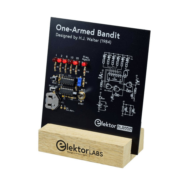
Pull Down Lever For Highest Score!
This Elektor Circuit Classic from 1984 shows a playful application of CMOS 400x series logic ICs in combination with LEDs, a highly popular combination at the time. The project imitates a spinning-digit type slot machine.
The Game
To play the game, first agree on the number of rounds. Player 1 actuates the switch lever as long as desired and releases it. The LEDs then show the score which is the sum of the 50-20-10-5 digits lit up. If the Play Again! LED lights, Player 1 has another, “free” round. If not, it’s Player 2’s turn. The players keep tab of their scores, and the highest score wins.
Features
LEDs Indicate Score
Multi-Player and Play Again!
Elektor Heritage Circuit Symbols
Tried & Tested by Elektor Labs
Educational & Geeky Project
Through-Hole Parts Only
Included
Printed Circuit Board
All Components
Wooden Stand
Bill of Materials
Resistors (5%, 250 mW)
R1,R2,R3,R4 = 100kΩ
R5,R6,R7,R8,R9,R10 = 1kΩ
Capacitors
C1 = 4.7nF, 10%, 50V, 5mm
C2 = 4.7μF, 10%, 63V, axial
C3,C4 = 100nF, 10 %, 50V, ceramic X7R, 5mm
Semiconductors
LED1-LED6 = red, 5mm (T1 3/4)
IC1 = 74HC4024
IC2 = 74HC132
Miscellaneous
S1 = switch, toggle, 21mm lever, SPDT, momentary
S2 = switch, tactile, 24V, 50mA, 6x6mm
S3 = switch, slide, SPDT
IC1,IC2 = IC socket, DIP14
BT1 = PCB-mount CR2032 battery retainer clip
Desktop Stand
PCB 230098-1
Not included: BT1 = CR2032 coin cell battery
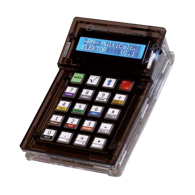
The Elektor MultiCalculator Kit is an Arduino-based multifunction calculator that goes beyond basic calculations. It offers 22 functions including light and temperature measurement, differential temperature analysis, and NEC IR remote control decoding. The Elektor MultiCalculator is a handy tool for use in your projects or for educational purposes.
The kit features a Pro Mini module as the computing unit. The PCB is easy to assemble using through-hole components. The enclosure consists of 11 acrylic panels and mounting materials for easy assembly. Additionally, the device is equipped with a 16x2 alphanumeric LCD, 20 buttons, and temperature sensors.
The Elektor MultiCalculator is programmable with the Arduino IDE through a 6-way PCB header. The available software is bilingual (English and Dutch). The calculator can be programmed with a programming adapter, and it is powered through USB-C.
Modes of Operation
Calculator
4-Ring Resistor Code
5-Ring Resistor Code
Decimal to Hexadecimal and Character (ASCII) conversion
Hexadecimal to Decimal and Character (ASCII) conversion
Decimal to Binary and Character (ASCII) conversion
Binary to Decimal and Hexadecimal conversion
Hz, nF, capacitive reactance (XC) calculation
Hz, µH, inductive reactance (XL) calculation
Resistance calculation of two resistors connected in parallel
Resistance calculation of two resistors connected in series
Calculation of unknown parallel resistor
Temperature measurement
Differential temperature measurement T1&T2 and Delta (δ)
Light measurement
Stopwatch with lap time function
Item counter
NEC IR remote control decoding
AWG conversion (American Wire Gauge)
Rolling Dice
Personalize startup message
Temperature calibration
Specifications
Menu languages: English, Dutch
Dimensions: 92 x 138 x 40 mm
Build time: approx. 5 hours
Included
PCB and though-hole components
Precut acrylic sheets with all mechanical parts
Pro Mini microcontroller module (ATmega328/5 V/16 MHz)
Programming adapter
Waterproof temperature sensors
USB-C cable
Downloads
Software
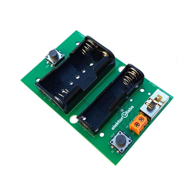
The Elektor Milliohmmeter Adapter uses the precision of a multimeter to measure very low resistance values. It is an adapter that converts a resistance into a voltage that can be measured with a standard multimeter.
The Elektor Milliohmmeter Adapter can measure resistances below 1 mΩ using a 4-wire (Kelvin) method. It is useful for locating short circuits on printed circuit boards (PCB).
The adapter features three measurement ranges – 1 mΩ, 10 mΩ, and 100 mΩ – selectable via a slide switch. It also includes onboard calibration resistors. The Elektor Milliohmmeter Adapter is powered by three 1.5 V AA batteries (not included).
Specifications
Measurement ranges
1 mΩ, 10 mΩ, 100 mΩ, 0.1%
Power supply
3x 1.5 V AA batteries (not included)
Dimensions
103 x 66 x 18 mm (compatible with Hammond 1593N-type enclosure, not included)
Special feature
On-board calibration resistors
Downloads
Documentation
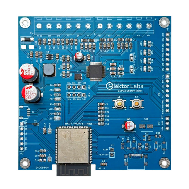
The Elektor ESP32 Energy Meter is a device designed for real-time energy monitoring and smart home integration. Powered by the ESP32-S3 microcontroller, it offers robust performance with modular and scalable features.
The device uses a 110/230 VAC to 12 VAC step-down transformer for voltage sampling, ensuring galvanic isolation and safety. Its compact PCB layout includes screw-type terminal blocks for secure connections, a Qwiic connector for additional sensors, and a programming header for direct ESP32-S3 configuration. The energy meter is compatible with single-phase and three-phase systems, making it adaptable for various applications.
The energy meter is simple to set up and integrates with Home Assistant, offering real-time monitoring, historical analytics, and automation capabilities. It provides accurate measurements of voltage, current, and power, making it a valuable tool for energy management in homes and businesses.
Features
Comprehensive Energy Monitoring: Get detailed insights into your energy usage for smarter management and cost savings.
Customizable Software: Tailor functionality to your needs by programming and integrating custom sensors.
Smart Home Ready: Compatible with ESPHome, Home Assistant, and MQTT for full Smart Home integration.
Safe & Flexible Design: Operates with a 110/230 VAC to 12 VAC step-down transformer and features a pre-assembled SMD board.
Quick Start: Includes one Current Transformer (CT) sensor and access to free setup resources.
Specifications
Microcontroller
ESP32-S3-WROOM-1-N8R2
Energy Metering IC
ATM90E32AS
Status Indicators
4x LEDs for power consumption indication2x Programmable LEDs for custom status notifications
User Input
2x Push buttons for user control
Display Output
I²C OLED display for real-time power consumption visualization
Input Voltage
12~16 VAC (via a step-down transformer 110/230 VAC to 12 VAC)
Clamp Current Sensor
YHDC SCT013-000 (100 A/50 mA) included
Smart Home Integration
ESPHome, Home Assistant, and MQTT for seamless connectivity
Connectivity
Header for programming, Qwiic for sensor expansion
Applications
Supports single-phase and three-phase energy monitoring systems
Dimensions
79.5 x 79.5 mm
Included
1x Partly assembled board (SMDs are pre-mounted)
2x Screw terminal block connectors (not mounted)
1x YHDC SCT013-000 current transformer
Required
Power transformer not included
Downloads
Datasheet (ESP32-S3-WROOM-1)
Datasheet (ATM90E32AS)
Datasheet (SCT013-000)
Frequently Asked Questions (FAQ)
From Prototype to Finished Product
What started as an innovative project to create a reliable and user-friendly energy meter using the ESP32-S3 microcontroller has evolved into a robust product. Initially developed as an open-source project, the ESP32 Energy Meter aimed to provide precise energy monitoring, smart home integration and more. Through meticulous hardware and firmware development, the energy meter now stands as a compact, versatile solution for energy management.
,
by Lobna Belarbi
Must-Have Boards, Kits & Tools to Start Your Arduino Journey with Elektor
Whether you're a newcomer eager to explore the world of microcontrollers or an experienced maker seeking to expand your toolkit, Elektor offers a curated selection...
,
by Udo Bormann
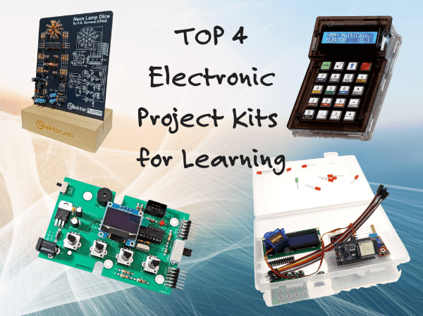
Top 4 Elektor Electronics Project Kits for Learning and Skill Development
Discover four of Elektor’s most exciting electronics kits — from IoT and Arduino to retro logic and motion control. Whether you're just starting out or...