
Search results for "rhine OR tower OR clock OR mk2 OR a OR b"
-
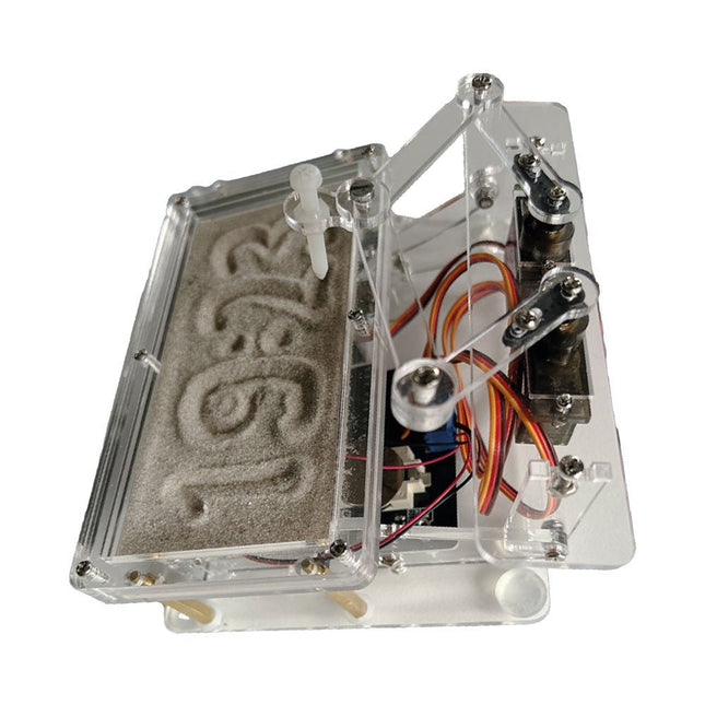
Elektor Labs Elektor Sand Clock for Raspberry Pi Pico
Raspberry Pi-based Eye Catcher A standard sand clock just shows how time passes. In contrast, this Raspberry Pi Pico-controlled sand clock shows the exact time by “engraving” the four digits for hour and minute into the layer of sand. After an adjustable time the sand is flattened out by two vibration motors and everything begins all over again. At the heart of the sand clock are two servo motors driving a writing pen through a pantograph mechanism. A third servo motor lifts the pen up and down. The sand container is equipped with two vibration motors to flatten the sand. The electronic part of the sand clock consists of a Raspberry Pi Pico and an RTC/driver board with a real-time clock, plus driver circuits for the servo motors. A detailed construction manual is available for downloading. Features Dimensions: 135 x 110 x 80 mm Build time: approx. 1.5 to 2 hours Included 3x Precut acrylic sheets with all mechanical parts 3x Mini servo motors 2x Vibration motors 1x Raspberry Pi Pico 1x RTC/driver board with assembled parts Nuts, bolts, spacers, and wires for the assembly Fine-grained white sand
€ 49,95€ 39,95Best Price
-

Elektor Labs Elektor Sand Clock for Raspberry Pi Pico (incl. Laser Head Upgrade)
This bundle contains the popular Elektor Sand Clock for Raspberry Pi Pico and the new Elektor Laser Head Upgrade, offering even more options for displaying the time. Not only can you "engrave" the current time in sand, you can now alternatively write it on a glow-in-the-dark foil or create green drawings. Contents of the bundle Elektor Sand Clock for Raspberry Pi Pico (normal price: €50) Elektor Laser Head Upgrade for Sand Clock (normal price: €35) Elektor Sand Clock for Raspberry Pi (Raspberry Pi-based Eye Catcher) A standard sand clock just shows how time passes. In contrast, this Raspberry Pi Pico-controlled sand clock shows the exact time by "engraving" the four digits for hour and minute into the layer of sand. After an adjustable time the sand is flattened out by two vibration motors and everything begins all over again. At the heart of the sand clock are two servo motors driving a writing pen through a pantograph mechanism. A third servo motor lifts the pen up and down. The sand container is equipped with two vibration motors to flatten the sand. The electronic part of the sand clock consists of a Raspberry Pi Pico and an RTC/driver board with a real-time clock, plus driver circuits for the servo motors. A detailed construction manual is available for downloading. Features Dimensions: 135 x 110 x 80 mm Build time: approx. 1.5 to 2 hours Included 3x Precut acrylic sheets with all mechanical parts 3x Mini servo motors 2x Vibration motors 1x Raspberry Pi Pico 1x RTC/driver board with assembled parts Nuts, bolts, spacers, and wires for the assembly Fine-grained white sand Elektor Laser Head Upgrade for Sand Clock The new Elektor Laser Head transforms the Sand Clock into a clock that writes the time on glow-in-the-dark film instead of sand. In addition to displaying the time, it can also be used to create ephemeral drawings. The 5 mW laser pointer, with a wavelength of 405 nm, produces bright green drawings on the glow-in-the-dark film. For best results, use the kit in a dimly lit room. Warning: Never look directly into the laser beam! The kit includes all the necessary components, but soldering three wires is required. Note: This kit is also compatible with the original Arduino-based Sand Clock from 2017. For more details, see Elektor Magazine 1-2/2017 and Elektor Magazine 1-2/2018.
€ 84,95€ 69,95Best Price
-
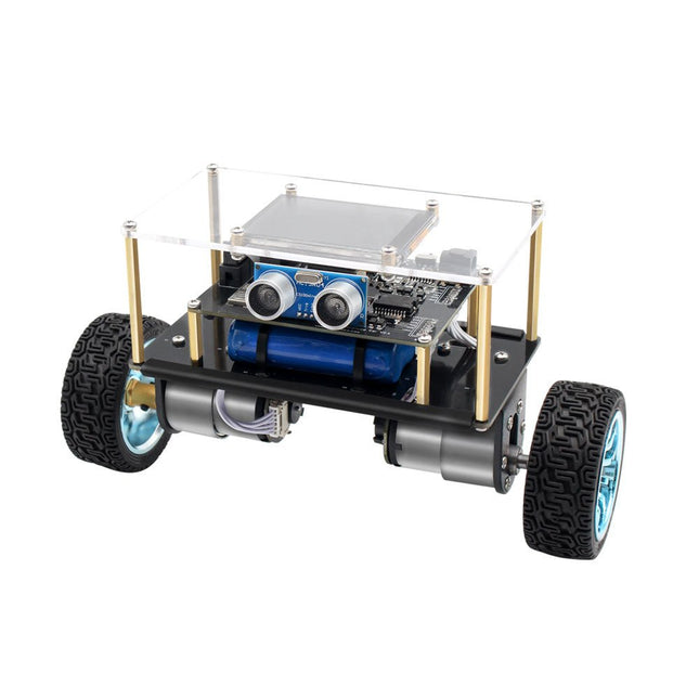
Elektor Labs Elektor Mini-Wheelie Self-Balancing Robot
Arduino-compatible, ESP32-controlled, 2-wheeled Balancing Robot The Elektor Mini-Wheelie is an experimental autonomous self-balancing robot platform. Based on an ESP32-S3 microcontroller, the self-balancing robot is fully programmable using the Arduino environment and open-source libraries. Its wireless capabilities allow it to be controlled remotely over Wi-Fi, Bluetooth or ESP-NOW or to communicate with a user or even another robot. An ultrasonic transducer is available for detecting obstacles. Its color display can be used for displaying cute facial expressions or, for the more down-to-earth users, cryptic debug messages. The robot comes as a neat kit of parts that you must assemble yourself. Everything is included, even a screwdriver. Note: The Mini-Wheelie is an educational development platform intended for learning, experimentation, and robotics development. It is not classified as a toy for children, and its features, documentation, and intended audience reflect this purpose. The product is aimed at students, educators, and developers who wish to explore robotics, programming, and hardware integration in an educational setting. Specifications ESP32-S3 microcontroller with Wi-Fi and Bluetooth MPU6050 6-axis Inertial Measurement Unit (IMU) Two independently controlled 12 V electric motors with tachometer Ultrasonic transducer 2.9" TFT color display (320 x 240) MicroSD card slot Battery power monitor 3S rechargeable Li-Po battery (11.1 V/2200 mAh) Battery charger included Arduino-based open-source software Dimensions (W x L x H): 23 x 8 x 13 cm Included 1x ESP32-S3 Mainboard + MPU6050 module 1x LCD board (2.9 inch) 1x Ultrasonic sensor 1x Battery pack (2200 mAh) 1x Battery charger 1x Motor tyre kit 1x Case board 1x Acrylic board 1x Screwdriver 1x Protective strip 1x Flex cable B (8 cm) 1x Flex cable A (12 cm) 1x Flex cable C 4x Copper column A (25 mm) 4x Copper column B (55 mm) 4x Copper column C (5 mm) 2x Plastic nylon column 8x Screws A (10 mm) 24x Screws B (M3x5) 8x Nuts 24x Metal washers 2x Zip tie 1x MicroSD card (32 GB) Downloads Documentation
€ 99,95€ 79,95Best Price
-

Siglent Siglent SDG2042X 2-ch Arbitrary Waveform Generator (40 MHz)
Siglent's SDG2000X is a series of dual-channel function/arbitrary waveform generators with specifications of up to 120 MHz maximum bandwidth, 1.2 GSa/s sampling rate and 16-bit vertical resolution. The proprietary TrueArb & EasyPulse techniques help to solve the weaknesses inherent in traditional DDS generators when generating arbitrary, square and pulse waveforms. With advantages above, SDG2000X can provide users with a variety of high fidelity and low jitter signals, which can meet the growing requirements of complex and extensive applications. Features Dual-channel, 40 MHz bandwidth, 20Vpp maximum output amplitude, high fidelity output with 80dB dynamic range. High-performance sampling system with 1.2GSa/s sampling rate and 16-bit vertical resolution. No detail in your waveforms will be lost. Innovative TrueArb technology, based on a point-by-point architecture, supports any 8pts~8Mpts Arb waveform with a sampling rate in range of 1μSa/s~75MSa/s. Innovative EasyPulse technology, capable of generating lower jitter Square or Pulse waveforms, brings a wide range and extremely high precision in pulse width and rise/fall times adjustment. Plenty of analog and digital modulation types: AM, DSB-AM, FM, PM, FSK, ASK and PWM. Sweep and Burst functions. High precision Frequency Counter. Standard interfaces: USB Host, USB DeviceUSBTMC, LAN (VXI-11) Optional interface: GPIB. 4.3” touch screen display for easier operation. Specifications Maximum output frequency 40 MHz Output channels 2 Sampling rate 1.2 GSa/s (4X Interpolation) Wave length CH1: 16 Kpts, CH2: 512 Kpts Frequency resolution 1 μHz Vertical resolution 16 bit Standard interfaces Standard interfaces: USB Host, USB Device (USBTMC), LAN (VXI-11) High-performance Sampling System Benefiting from a 1.2GSa/s and 16-bit sampling system, SDG2000X achieves extremely high accuracy performance in both time domain and amplitude, which results in more accurately reconstructed waveforms and lower distortion. Innovative EasyPulse Technology When a Square/Pulse waveform is generated by DDS, there will be a one-clock-jitter if the sampling rate is not an integer-related multiple of the output frequency. SDG2000X EasyPulse technology successfully overcomes this weakness in DDS designs and helps to produce low jitter Square/Pulse waveforms. Innovative TrueArb Technology For arbitrary waveforms, TrueArb not only has all the advantages of traditional DDS, but also eliminates the probability that DDS may cause serious jitter and distortion. Easy controll with 4.3” Touch Screen Display and Arbitrary Waveform Software EasyWave The 4.3” touch screen display, makes operation much more convenient. And EasyWave is a powerful arbitrary waveform editing software that supports several ways to generate arbitrary waveform such as manual drawing, line-drawing, equation-drawing, coordinate-drawing, etc. It is quite convenient for users to edit their own arbitrary waveforms through EasyWave. Included Siglent SDG2042X Arbitrary Function Generator User Manual Guarantee Card CD (including EasyWave 1.0 computer software system) Power Cord USB Cable Quick Start Guide
€ 560,39
-
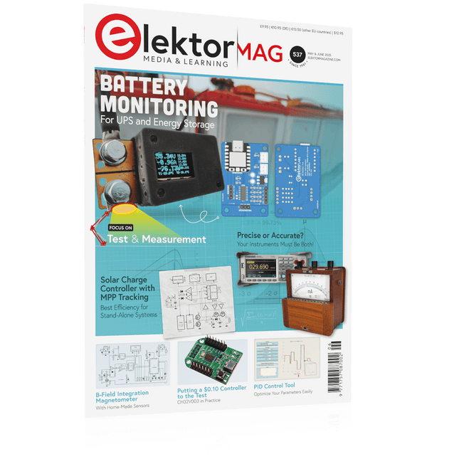
Elektor May/June 2025 (EN)
Elektor GREEN and GOLD members can download their digital edition here. Not a member yet? Click here. PbMonitor v1.0A Battery-Monitoring System for UPS and Energy Storage Applications Solar Charge Controller with MPPT (1)Basic Principles of a Solar Controller for Stand-Alone Systems B-Field Integration Magnetometer With Home-Made Sensors Precise or Accurate?Your Instruments Need to Be Both! AD7124 A Precision ADC in PracticeFeatures for Sensor Signal Conditioning PID Control ToolOptimize Your Parameters Easily embedded world 2025 Starting Out in Electronics……Continues with Tone Control Academy Pro BoxBook + Online Course + Hardware Milliohmmeter AdapterUses the Precision of Your Multimeter The Next Leap in SemiconductorsOnward Toward 1.4 nm Through-Hole Technology ConnectorsThe Best of Two Worlds: THR Frequency CounterPortable and Auto-Calibrating Via GPS Analog MetersPeculiar Parts, the Series Stand-Alone Crystal TesterHow Accurate Is Your Clock Source? Low-Cost I²C TesterConnect I²C Devices Directly to Your PC From Life’s ExperienceWho Doesn’t Honor the Small Things? 2025: An AI OdysseyThe Transformative Impact on Software Development Err-lectronicsCorrections, Updates, and Readers’ Letters Raspberry Pi Standalone MIDI Synthesizer (2)Enhancing Our Setup with Intelligence Nortonized Wien Bridge OscillatorSmall Changes Yield Significant Improvements Putting a $0.10 Controller to the TestThe CH32V003 RISC-V Microcontroller and MounRiver Studio in Practice An FPGA-Based Audio Player with Equalizer (2)Adding Volume Control, Advanced Mixing, and a Web Interface
€ 10,95
-

OWON OWON DGE3062 2-ch Arbitrary Waveform Generator (60 MHz)
The OWON DGE3062 is a 14-bit function generator with a bandwidth of 60 MHz. It has 5 basic waveforms, 160 built-in arbitrary waveforms and the following comprehensive modulation functions: AM, FM, PM, PWM, FSK, 3FSK, 4FSK, PSK, ASK, BPSK, OSK, DSBAM, QPSK, SUM, sweep, Burst. Features Max. 60 MHz frequency output, 300 MSa/s Sample rate 14 bits Vertical Resolution, 100K Arb waveform length Comprehensive waveform output: 5 basic waveforms, and 160 built-in arbitrary waveforms Comprehensive modulation functions: AM, FM, PM, PWM, FSK, 3FSK, 4FSK, PSK, ASK, BPSK, OSK, DSBAM, QPSK, SUM, sweep, Burst SCPI and LabVIEW supported 3.6 inch LCD (480 x 272 pixels) Specifications Channel 2 Frequency Output 60 MHz Sample Rate 300 MSa/s Vertical Resolution 14 bits Waveform Standard Waveform Sine, square, pulse, ramp, noise Arbitrary Waveform Exponential rise, exponential fall, sin(x)/x, step wave, and others, total 160 built-in waveforms Frequency (resolution 1 μHz) Sine 1 μHz-60 MHz Square 1 μHz ~ 20 MHz Pulse 1 μHz ~ 20 MHz Ramp 1 μHz ~ 2 MHz Noise 20 MHz (-3 dB, typical) Arbitrary Waveform 1 μHz ~10 MHz Arbitrary Waveform Length 2 points – 100K points Sample Rate 300 MSa/s Amplitude Into 50Ω load 1mVpp ~ 10Vpp (≤10Hz), 1mVpp ~ 5Vpp (≤60 MHz) DC Offset Range (AD+DC ±(10 Vpk – Amplitude Vpp/2) high resistance±(5 Vpk – Amplitude Vpp/2) 50 Ω DC offset resolution 1 mV or 4 digits Load Impedance 50 Ω (typical) DC offset Accuracy ±(1% of |setting| + 1 mV + amplitude Vpp * 0.5%) Modulation Type AM,FM, PM, PWM, FSK, 3FSK, 4FSK, PSK, ASK, BPSK, OSK, DSB-AM, QPSK, SUM, Sweep, Burst Frequency Counter Function Frequency, period Frequency Range 100 MHz ~ 100 MHz Frequency Resolution 6 digits Input/Output Display 3.6” LCD Input mode External modulation input, external trigger input, external reference clock input/output Communication Interface USB Host, USB Device Mechanical specifications Dimensions (W x H x D) 200 x 92 x 157 mm Weight 0.8 kg Included 1x OWÒN DGE3062 Arbitrary Waveform Generator 1x Power Cord 1x Quick Guide 1x USB Cable 1x Q9 Cable 1x BNC to Alligator Clip Downloads Quick Guide Manual Software
€ 212,50
-

OWON OWON XDG2035 2-ch Arbitrary Waveform Generator (35 Mhz)
The 2-channel OWON XDG2035 is a function/waveform generator that can generate signals with a maximum frequency of 35 Hz. The generator has a resolution of 1 µHz and a sample rate of 500 MSa/s. The OWON XDG2035 is capable of generating 6 standard waveforms and 150 arbitrary waveforms. With the included software you can write advanced functions up to 10 million points. Waveforms can be saved to the function generator's internal memory using a PC via USB or LAN. The OWON XDG2035 also supports SCPI commands and LabView. The function generator has an integrated high-quality frequency counter, which can operate from 100 to 200 MHz. Features Max. 35 MHz frequency output 500 MSa/s Sample rate, Vertical resolution 1μHz 14 bits Vertical Resolution, 10 Marb waveform length Comprehensive waveform output: 6 basic waveforms,and 150 built-in arbitrary waveforms Comprehensive modulation functions: AM, FM, PM, FSK, 3FSK, 4FSK, PSK, OSK, ASK, BPSK, PWM, Sweep, and Burst High-accuracy frequency counter integrated, supported range 100-200 MHz SCPI and LabVIEW supported 7 inch multi-touch screen (800 x 480 pixels) Specifications Channel 2 Frequency Output 35 MHz Sample Rate 500 MSa/s Vertical Resolution 14 bits Waveform Standard Waveform sine, square, pulse, ramp, noise, and harmonic Arbitrary Waveform exponential rise, exponential fall, sin(x)/x, step wave, and others, total 150 built-in waveforms, and user-defined arbitrary waveform Frequency (resolution 1 μHz) Sine 1 μHz-100 MHz Square 1 μHz ~ 30 MHz Pulse 1 μHz ~ 25 MHz Ramp 1 μHz ~ 3 MHz Noise (-3 dB, typical) 100 MHz Arbitrary Waveform 1 μHz ~ 15 MHz Harmonic 1 μHz ~ 50 MHz Accuracy ±2ppm, 25°C ±5°C Waveform Length 2 points - 10M points Amplitude Into 50Ω load 1mVpp ~ 10Vpp (≤25 MHz); 1mVpp ~ 5Vpp (≤60 MHz); 1mVpp ~ 2.5Vpp (≤100 MHz) Modulation Type AM, DSB-AM, FM, PM, ASK, FSK, PSK, BPSK, QPSK, 3FSK, 4FSK, OSK, PWM, SUM Frequency Counter Function Frequency, period, +width, -width, +duty, and -duty Frequency Range 100 ~ 200 MHz Frequency Resolution 7 digits Input/Output Input mode frequency counter, external modulation input, external trigger input, internal clock output, external reference clock input/output Communication Interface USB Host, USB Device, LAN, RS232 (optional) Mechanical specifications Dimensions 340 x 177 x 90 mm Weight 2.3 kg Included 1x OWON XDG2035 1x Power Cord 1x CD-ROM 1x Quick start guide 1x USB Cable 1x BNC-BNC Cable Downloads Quick Guide
€ 339,00
-
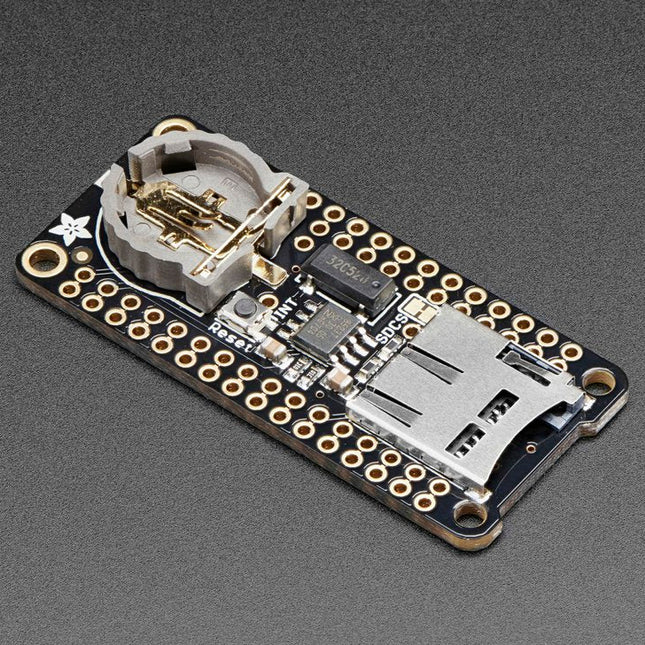
Adafruit Adafruit Adalogger FeatherWing (RTC + SD Add-on)
This FeatherWing will make it easy to add data logging to any Feather Board you might have. You get both an I²C real-time clock (PCF8523) with 32 KHz crystal and battery backup, and a microSD socket that connects to the SPI port pins (+ extra pin for CS). Note: FeatherWing doesn't come with a microSD card. A CR1220 coin cell is required to use the RTC battery-backup capabilities. If you're not using the RTC part of the FeatherWing, a battery is not required. To talk to the microSD card socket Arduino's default SD library is recommended. Some light soldering is required to attach the headers onto the Wing. Pinouts Power pins On the bottom row, the 3.3 V (second from left) and GND (fourth from left) pin are used to power the SD card and RTC (to take a load off the coin cell battery when main power is available) RTC & I²C Pins In the top right SDA (rightmost) and SCL (to the left of SDA) are used to talk to the RTC chip. SCL - I²C clock pin to connect to your microcontroller's I2C clock line. This pin has a 10 kΩ pull-up resistor to 3.3 V SDA - I²C data pin to connect to your microcontroller's I2C data line. This pin has a 10 kΩ pull-up resistor to 3.3 V There's also a breakout for INT which is the output pin from the RTC. It can be used as an interrupt output or it could also be used to generate a square wave. Note that this pin is an open drain - you must enable the internal pull-up on whatever digital pin it is connected to. SD & SPI Pins Starting from the left you've got SPI Clock (SCK) - output from feather to wing SPI Master Out Slave In (MOSI) - output from feather to wing SPI Master In Slave Out (MISO) - input from wing to feather These pins are in the same location on every Feather. They are used for communicating with the SD card. When the SD card is not inserted, these pins are completely free.
-
Elektor Bundles Raspberry Pi 5 RTL-SDR V4 (Bundle)
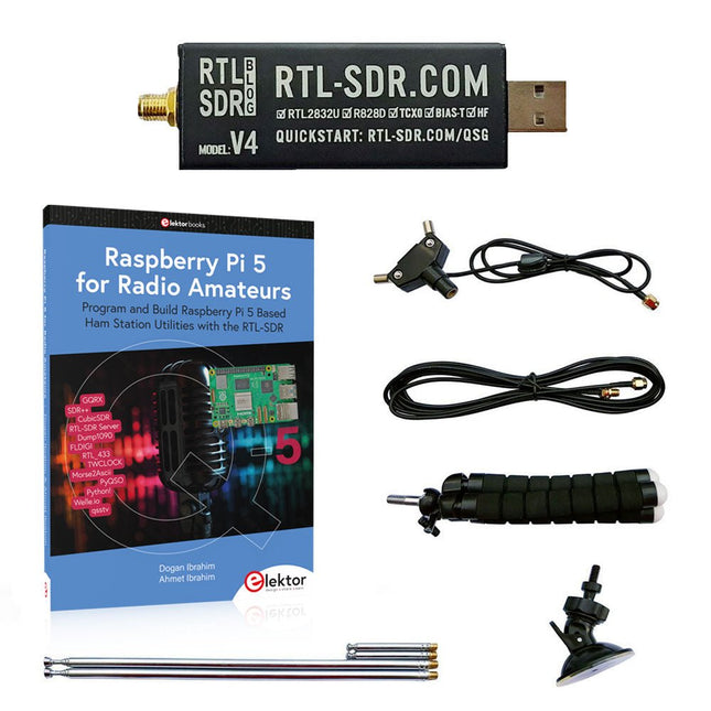
Program and build Raspberry Pi based ham station utilities, tools, and instruments The improved RTL-SDR V4 allows you to receive radio signals between 500 kHz and 1.75 GHz from stations utilizing different bands including MW/SW/LW broadcast, ham radio, utility, air traffic control, PMR, SRD, ISM, CB, weather satellite, and radio astronomy. The book Raspberry Pi 5 for Radio Amateurs gives extensive coverage of deploying the RTL-SDR kit through the use of a Raspberry Pi 5. This bundle contains: RTL-SDR V4 (incl. Dipole Antenna Kit) (normal price: €75) Raspberry Pi 5 for Radio Amateurs (normal price: €40) RTL-SDR V4 (Software Defined Radio) with Dipole Antenna Kit RTL-SDR is an affordable dongle that can be used as a computer-based radio scanner for receiving live radio signals between 500 kHz and 1.75 GHz in your area. The RTL-SDR V4 offers several improvements over generic brands including use of the R828D tuner chip, triplexed input filter, notch filter, improved component tolerances, a 1 PPM temperature compensated oscillator (TCXO), SMA F connector, aluminium case with passive cooling, bias tee circuit, improved power supply, and a built in HF upconverter. RTL-SDR V4 comes with the portable dipole antenna kit. It is great for beginners as it allows for terrestrial and satellite reception and easy to mount outdoors and designed for portable and temporary outside usage. Features Improved HF reception: V4 now uses a built-in upconverter instead of using a direct sampling circuit. This means no more Nyquist folding of signals around 14.4 MHz, improved sensitivity, and adjustable gain on HF. Like the V3, the lower tuning range remains at 500 kHz and very strong reception may still require front end attenuation/filtering. Improved filtering: The V4 makes use of the R828D tuner chip, which has three inputs. The SMA input has been triplexed input into 3 bands: HF, VHF and UHF. This provides some isolation between the 3 bands, meaning out of band interference from strong broadcast stations is less likely to cause desensitization or imaging. Improved filtering x2: In addition to the triplexing, the open drain pin on the R828D can be also used, which allows to add simple notch filters for common interference bands such as broadcast AM, broadcast FM and the DAB bands. These only attenuate by a few dB, but may still help. Improved phase noise on strong signals: Due to an improved power supply design, phase noise from power supply noise has been significantly reduced. Less heat: Another advantage of the improved power supply is low power consumption and less heat generation compared to the V3. Included 1x RTL-SDR V4 dongle (R828D RTL2832U 1PPM TCXO SMA) 2x 23 cm to 1 m telescopic antenna 2x 5 cm to 13 cm telescopic antenna 1x Dipole antenna base with 60 cm RG174 1x 3 m RG174 extension cable 1x Flexible tripod mount 1x Suction cup mount Downloads Datasheet User Guide Quick Start Guide SDR# User Guide Dipole Antenna Guide Book: Raspberry Pi 5 for Radio Amateurs The RTL-SDR devices (V3 and V4) have gained popularity among radio amateurs because of their very low cost and rich features. A basic system may consist of a USB based RTL-SDR device (dongle) with a suitable antenna, a Raspberry Pi 5 computer, a USB based external audio input-output adapter, and software installed on the Raspberry Pi 5 computer. With such a modest setup, it is possible to receive signals from around 24 MHz to over 1.7 GHz. This book is aimed at amateur radio enthusiasts and electronic engineering students, as well as at anyone interested in learning to use the Raspberry Pi 5 to build electronic projects. The book is suitable for both beginners through experienced readers. Some knowledge of the Python programming language is required to understand and eventually modify the projects given in the book. A block diagram, a circuit diagram, and a complete Python program listing is given for each project, alongside a comprehensive description. The following popular RTL-SDR programs are discussed in detail, aided by step-by-step installation guides for practical use on a Raspberry Pi 5: SimpleFM GQRX SDR++ CubicSDR RTL-SDR Server Dump1090 FLDIGI Quick RTL_433 aldo xcwcp GPredict TWCLOCK CQRLOG klog Morse2Ascii PyQSO Welle.io Ham Clock CHIRP xastir qsstv flrig XyGrib FreeDV Qtel (EchoLink) XDX (DX-Cluster) WSJT-X The application of the Python programming language on the latest Raspberry Pi 5 platform precludes the use of the programs in the book from working on older versions of Raspberry Pi computers.
-
Raspberry Pi Foundation RTC Battery for Raspberry Pi 5
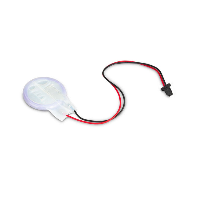
The power-management IC used on Raspberry Pi 5 integrates a real-time clock, and charging circuitry for a button cell which can power the clock while main power is disconnected. This Panasonic ML-2020 lithium manganese dioxide battery with a two-pin plug and a double-sided adhesive pad can be connected directly to the battery connector of the Raspberry Pi 5 and attached to the inside of a case or another convenient location.


About Elektor
Read more
-
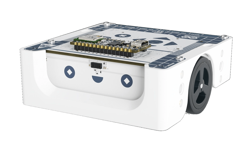
, by Clemens Valens Inspiring the Next Generation with Arduino Alvik
In our rapidly evolving, technology-driven society, the demand for technicians, engineers, and developers continues to rise. Addressing the challenge of recruiting and training these essential...
