Search results for "elektor OR special OR raspberry OR pi OR und OR pico OR pdf"
-
Elektor Digital Elektor Special: Raspberry Pi and Pico (PDF)
Contents Projects PicoVoiceVoice alienation and sound effects with the Raspberry Pi Pico Navigation with Vibration Feedback POV Display Pulse Width Modulation (PWM) with the Raspberry Pi Pico Wi-Fi with the Raspberry Pi Pico 'Hello World' from the Raspberry Pi Pico and RP2040A look at the Raspberry Pi Foundation’s first microcontroller Simple On-Off Temperature Controller with Raspberry Pi HAT Multitasking with the Raspberry PiShowcase: a traffic lights controller The Raspberry Pi Ruler GadgetFun with a time-of-flight sensor Raspberry Pi Buffer Board (Mk. 1)Never blow up the I/O again FM radio with RDSA top HAT project for the Raspberry Pi LoRa with the Raspberry Pi PicoFun with MicroPython! Tutorials Qt for the Raspberry Pi Raspberry Pi Pico Programmingwith MicroPython and Thonny Raspberry Pi Full StackRPi and RF24 at the heart of a sensor network Raspberry Pi Bash Command Cheat Sheet Community Java on the Raspberry PiAn interview with Frank Delporte Reviews Introducing the New Raspberry Pi Pico W, H, and WH Secure Boot Solution for Raspberry PiRetrofit security at a reasonable price Review: SmartPi – Smart Meter Extension for Raspberry Pi Review: The Enviro+ Raspberry Pi HATMeasuring environmental data with Raspberry Pi and the HAT Enviro+ Review: Meet the Raspberry Pi 4All new but still good? Raspberry Pi Gets a Fast 3.5' Touch DisplayMore power at no extra charge Book Launch: Raspberry Pi for Radio Amateurs
€ 11,95
Members: € 10,76
-
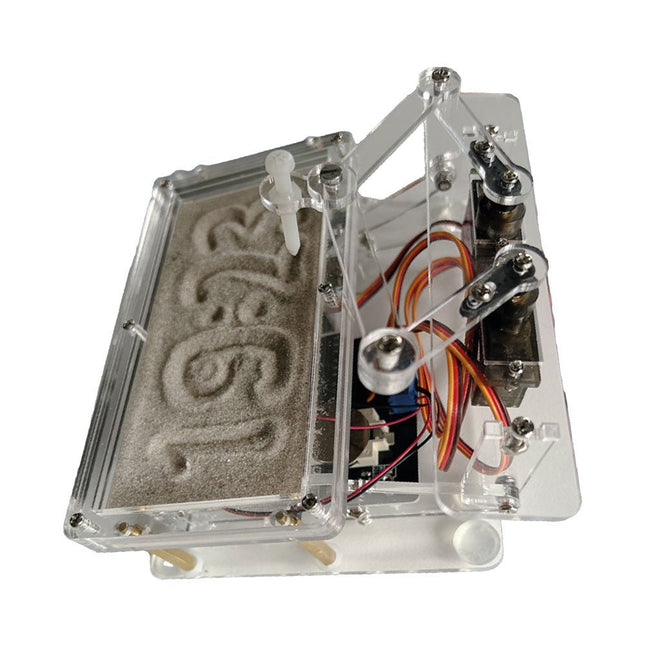
Elektor Labs Elektor Sand Clock for Raspberry Pi Pico
Raspberry Pi-based Eye Catcher A standard sand clock just shows how time passes. In contrast, this Raspberry Pi Pico-controlled sand clock shows the exact time by “engraving” the four digits for hour and minute into the layer of sand. After an adjustable time the sand is flattened out by two vibration motors and everything begins all over again. At the heart of the sand clock are two servo motors driving a writing pen through a pantograph mechanism. A third servo motor lifts the pen up and down. The sand container is equipped with two vibration motors to flatten the sand. The electronic part of the sand clock consists of a Raspberry Pi Pico and an RTC/driver board with a real-time clock, plus driver circuits for the servo motors. A detailed construction manual is available for downloading. Features Dimensions: 135 x 110 x 80 mm Build time: approx. 1.5 to 2 hours Included 3x Precut acrylic sheets with all mechanical parts 3x Mini servo motors 2x Vibration motors 1x Raspberry Pi Pico 1x RTC/driver board with assembled parts Nuts, bolts, spacers, and wires for the assembly Fine-grained white sand
€ 49,95€ 39,95
Best Price
-

Elektor Bundles Elektor Raspberry Pi Pico Advanced Kit (Bundle)
Comprehensive Book-Hardware Bundle for the RP2040 Microcontroller with over 80 Projects Unlock the potential of modern controller technology with the Raspberry Pi Pico in this bundle. Perfect for both beginners and experienced users, the easy-to-follow guide takes you from the basics of electronics to the complexities of digital signal processing. With the Raspberry Pi Pico, the dedicated hardware kit and MicroPython programming, you will learn the key principles of circuit design, data collection, and processing. Get hands-on with over 80 projects like a stopwatch with an OLED display, a laser distance meter, and a servo-controlled fan. These projects are designed to help you apply what you've learned in real-world scenarios. The book also covers advanced topics like wireless RFID technology, object detection, and sensor integration for robotics. Whether you're looking to build your skills in electronics or dive deeper into embedded systems, this bundle is the perfect resource to help you explore the full potential of the Raspberry Pi Pico. Contents of the Bundle 1x Project Book (273 pages) 1x Raspberry Pi Pico H 1x Smart Car Kit Electronic Parts 2x Solderless breadboard (400 holes) 1x Solderless breadboard (170 holes) 5x Colorful 5 mm LEDs (green, red, blue, yellow and white) 1x Laser transmitter 1x Passive buzzer 1x Micro USB cable (30 cm) 1x 65 Jumper wires 1x 20 cm male to female Dupont wire 1x Clear case 1x Magnet (diameter: 8 mm, thickness: 5 mm) 1x Rotary potentiometer 10x 2 KΩ resistors 2x M2.5x30 mm copper pillars 10x Phillips pan head screws 10x M2.5 nickel hex nuts 1x 2-inch dual-purpose screwdriver Modules 1x RGB module 1x 9G servo 1x Dual-axis XY joystick module 1x RC522 RFID module 1x 4 Bits digital LED display module 1x Traffic light display module 1x Rotary Encoder module 1x 1602 LCD Display module (Blue) 1x Photoresistor module 1x DC motor with male Dupont wire 1x Fan blade 1x Raindrops module 1x OLED module 1x Membrane switch keyboard 1x Mini magnetic spring module 1x Infrared remote control 1x Infrared receiver module 1x DC stepper motor driver board 1x Button Sensors 1x Vibration sensor 1x Soil moisture sensor 1x Sound sensor 1x Mini PIR motion sensor 1x Temperature & Humidity sensor 1x Flame sensor 2x Crash sensor 2x Tracking sensor 1x Ultrasonic sensor
€ 99,95€ 79,95
Best Price
-

Elektor Labs Elektor Sand Clock for Raspberry Pi Pico (incl. Laser Head Upgrade)
This bundle contains the popular Elektor Sand Clock for Raspberry Pi Pico and the new Elektor Laser Head Upgrade, offering even more options for displaying the time. Not only can you "engrave" the current time in sand, you can now alternatively write it on a glow-in-the-dark foil or create green drawings. Contents of the bundle Elektor Sand Clock for Raspberry Pi Pico (normal price: €50) Elektor Laser Head Upgrade for Sand Clock (normal price: €35) Elektor Sand Clock for Raspberry Pi (Raspberry Pi-based Eye Catcher) A standard sand clock just shows how time passes. In contrast, this Raspberry Pi Pico-controlled sand clock shows the exact time by "engraving" the four digits for hour and minute into the layer of sand. After an adjustable time the sand is flattened out by two vibration motors and everything begins all over again. At the heart of the sand clock are two servo motors driving a writing pen through a pantograph mechanism. A third servo motor lifts the pen up and down. The sand container is equipped with two vibration motors to flatten the sand. The electronic part of the sand clock consists of a Raspberry Pi Pico and an RTC/driver board with a real-time clock, plus driver circuits for the servo motors. A detailed construction manual is available for downloading. Features Dimensions: 135 x 110 x 80 mm Build time: approx. 1.5 to 2 hours Included 3x Precut acrylic sheets with all mechanical parts 3x Mini servo motors 2x Vibration motors 1x Raspberry Pi Pico 1x RTC/driver board with assembled parts Nuts, bolts, spacers, and wires for the assembly Fine-grained white sand Elektor Laser Head Upgrade for Sand Clock The new Elektor Laser Head transforms the Sand Clock into a clock that writes the time on glow-in-the-dark film instead of sand. In addition to displaying the time, it can also be used to create ephemeral drawings. The 5 mW laser pointer, with a wavelength of 405 nm, produces bright green drawings on the glow-in-the-dark film. For best results, use the kit in a dimly lit room. Warning: Never look directly into the laser beam! The kit includes all the necessary components, but soldering three wires is required. Note: This kit is also compatible with the original Arduino-based Sand Clock from 2017. For more details, see Elektor Magazine 1-2/2017 and Elektor Magazine 1-2/2018.
€ 84,95€ 69,95
Best Price
-

Elektor Digital Elektor Special: Power Supplies and Batteries (PDF)
Whatever the methods or even then financial means you have to make your circuits work, the power supply should rank high if not Number One in your considerations. The design block simply called “power supply” is hugely underrated both in electronics creation and repair. Yet, the “PSU” has enormous diversity and comes in wildly differing guises like AC/DC, generator, battery (rechargeable or not), PV panel, benchtop, linear or switch-mode, to mention but a few. The output ranges are also staggering like nano-amps to kiloamps and the same for voltages.This special covers the features and design aspects of power supplies.ContentsBasics Battery ManagementWhat to be aware of when using (Lithium) batteries. Fixed-Voltage Power Supply using Linear RegulatorsThe best result right after batteries. Light Energy HarvestingA small solar panel is used in an energy harvesting project to manage and charge four AAA cells. Mains Powered Adapter DesignBasic circuits and tips for transformers, rectification, filtering and stabilization. LM317 Soft StartThe high inrush current pulse should be avoided. Controllable RectifiersSome suggestions to keep the power loss in the linear regulator as low as possible. Components Worksheet: The LM117 / LM217 / LM317 Voltage Regulators SupercapsLow voltage but lots of current… or not? Reviews JOY-iT RD6006 Benchtop Power Supply Kit Siglent SDL1020X Programmable DC Electronic Load Projects Balcony Power PlantDIY solar balcony = speedy payback! DIY LiPo Supercharger KitFrom handcrafted to mass market Dual-Anode MOSFET ThyristorFaster and less wasteful than the old SCR Battery JuicerDo not throw away, squeeze! High-Voltage Power Supply with Curve TracerGenerate voltages up to 400 V and trace characteristics curves for valves and transistors High Voltage Supply for RIAAFor RIAA tube preamps and other applications. MicroSupplyA lab power supply for connected devices Phantom Power Supply using Switched CapacitorsVoltage tripler using three ICs The SMPS800RE Switch-Mode Supply for the Elektor Fortissimo-100Reliable, light and affordable Soft Start for PSUBe nice to your power supply – and its load UniLab 20-30 V, 3 A compact switch-mode lab power supply Tips Soft Start for Step-Down Switching Regulators Low Loss Current Limit Powerbank Surprise A Virtual Ground Battery Maintainer Battery Pack Discharger Connecting Voltage Regulators in Parallel
€ 11,95
Members: € 10,76
-
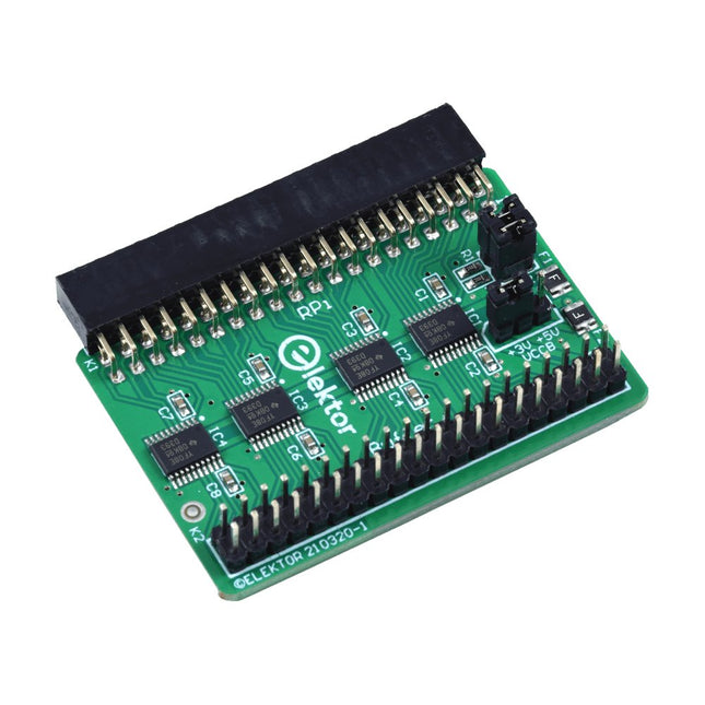
Elektor Labs Elektor Raspberry Pi Buffer Board
When you experiment with the Raspberry Pi on a regular basis and you connect a variety of external hardware to the GPIO port via the header you may well have caused some damage in the past. The Elektor Raspberry Pi Buffer Board is there to prevent this! The board is compatible with Raspberry Pi Zero, Zero 2 (W), 3, 4, 5, 400 and 500. All 26 GPIOs are buffered with bi-directional voltage translators to protect the Raspberry Pi when experimenting with new circuits. The PCB is intended to be inserted in the back of Raspberry Pi 400/500. The connector to connect to the Raspberry Pi is a right angled 40-way receptacle (2x20). The PCB is only a fraction wider. A 40-way flat cable with appropriate 2x20 headers can be connected to the buffer output header to experiment for instance with a circuit on a breadboard or PCB. The circuit uses 4x TXS0108E ICs by Texas Instruments. The PCB can also be put upright on a Raspberry Pi. Downloads Schematics Layout
€ 34,95€ 29,95
Best Price
-

Elektor Digital Elektor Circuit Special 2023 PDF (NL)
Elektor GREEN en GOLD leden kunnen deze uitgave hier downloaden.Nog geen lid? Klik hier om een lidmaatschap af te sluiten. Mini-zonnevoedingzon in, 3,3 V uit Solid-state stereo-audioschakelaarklikvrij en zonder bewegende onderdelen Grote RGB-digitmet through-hole WS2812 LED’s Microfoon-voorversterker met 48V-fantoomvoedingvoor podcasting en pro-audio Blokgolfgeneratoren met regelbare duty cycle en frequentiesimpele schakelingen met CMOS- en TTL-IC’s Eenvoudige dynamiekcompressorsofte aansturing, warm geluid Simpel elektronisch slot Actieve gelijkrichtervoor 2...40 V bij maximaal 3 A met tegenstroomonderdrukking Actieve boxen in- en uitschakelen Ongebalanceerd/gebalanceerd-convertermet RF-filter en DC-bescherming 2023: een AI-odysseewaar komt het vandaan en waar gaat het naar toe? Snelheidsregelaar voor ventilatormet handmatige en thermostaatmodus Laatste nieuwtjes van Arduino Project Hubnieuwe projecten uit de community Overbelastingsmonitorbewaakt netsnoeren Transistorloos knipperlicht in het donkeroscillator met alleen tweedraads onderdelen Morsecode-generatorvoor gebruik als baken of leermiddel! Programmeerbare video-DACvoor elk formaat tot RGB888 Kleintje klavierzonder bewegende onderdelen Dubbel-dobbel zonder microprocessordubbele dobbelsteen op een enkele print – plus enkele ontwerptrucs Elektronische vogelverschrikker Amusante, inspirerende en verbazingwekkende schakelingen LC/LP/HA-thermometernauwkeurige metingen en een binair display THD-generatorvervorming, maar dan opzettelijk Overtemperatuur-indicator met thyristorelektronische onderdelen ongebruikelijk gebruikt Een PTC-flipflop Sociale vogeleen tsjilpende Elektor Klassieker Neonlamp plus microcontroller Temperatuurgestabiliseerde IC-stroombronneutraliseer de temperatuurdrift van deze driebeners Regelbare tweede-orde hogetonen-boostergehoorsteuntje voor ouderen Edwin komt naar huisherinneringen na 53 jaar Eénarmige bandieteen eenvoudige, leuke, nostalgische en leerzame Elektor-klassieker! Eenvoudige digitaal gestuurde variabele weerstand Lekdetectorbeveiligt en alarmeert bij lekkages Eco-timer met automatische uitschakelingverbruikt niets in uitgeschakelde toestand! ChatGPT en Arduino Zenermetermeet de Z-spanning van Z-diodes ≤ 100 V Servotester ESP32 Windows-controller met gratis software Analoge en mixed-signal IC’s van Microchipzuinige signaalverwerking Interfacenormenfilter en overspanningsbeveiliging voor de I²C-bus Li-Ion accumonitorrestlading-indicator geeft visuele feedback PS/2-muis als draai-encoder (en meer...) Simpele schemerschakelaarvoor bestaande lampen of installaties Controller voor waterpompbereid je voor op hoogwater Kerstbal met FM-zonneradiomeer heb je voor de kerst niet nodig Trillingssensor met relaistik of schud om in te schakelen Doorgangstestergevoelig en niet storend In- en uitschakelen met een drukknop Regeling voor mini-boor (2023)een ontwerp uit 1980 herzien Digitale trillingssensorzet trillingen om in nauwkeurig getimede pulsen Ompoolbeveiliging met kleine spanningsval Goedkope frequentiestandaard Kleine DCF77-simulatornauwkeurige fake-tijdstandaard De Lilygo T-PicoC3combineert RP2040 en ESP32-C3 met een full-color TFT-display Hexadoku
€ 9,95
-
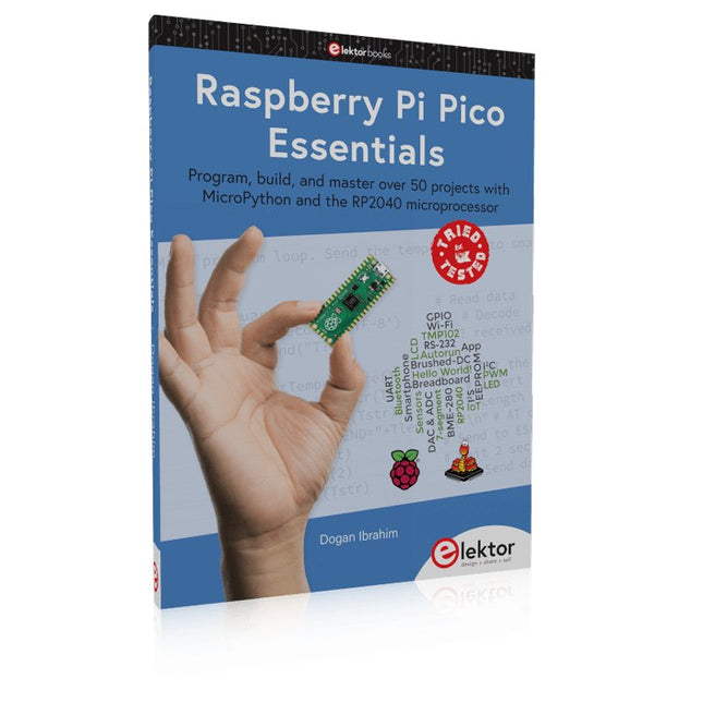
Elektor Publishing Raspberry Pi Pico Essentials
Program, build, and master over 50 projects with MicroPython and the RP2040 microprocessor The Raspberry Pi Pico is a high-performance microcontroller module designed especially for physical computing. Microcontrollers differ from single-board computers, like the Raspberry Pi 4, in not having an operating system. The Raspberry Pi Pico can be programmed to run a single task very efficiently within real-time control and monitoring applications requiring speed. The ‘Pico’ as we call it, is based on the fast, efficient, and low-cost dual-core ARM Cortex-M0+ RP2040 microcontroller chip running at up to 133 MHz and sporting 264 KB of SRAM, and 2 MB of Flash memory. Besides its large memory, the Pico has even more attractive features including a vast number of GPIO pins, and popular interface modules like ADC, SPI, I²C, UART, and PWM. To cap it all, the chip offers fast and accurate timing modules, a hardware debug interface, and an internal temperature sensor. The Raspberry Pi Pico is easily programmed using popular high-level languages such as MicroPython and or C/C++. This book is an introduction to using the Raspberry Pi Pico microcontroller in conjunction with the MicroPython programming language. The Thonny development environment (IDE) is used in all the projects described. There are over 50 working and tested projects in the book, covering the following topics: Installing the MicroPython on Raspberry Pi Pico using a Raspberry Pi or a PC Timer interrupts and external interrupts Analogue-to-digital converter (ADC) projects Using the internal temperature sensor and external temperature sensor chips Datalogging projects PWM, UART, I²C, and SPI projects Using Wi-Fi and apps to communicate with smartphones Using Bluetooth and apps to communicate with smartphones Digital-to-analogue converter (DAC) projects All projects given in the book have been fully tested and are working. Only basic programming and electronics experience is required to follow the projects. Brief descriptions, block diagrams, detailed circuit diagrams, and full MicroPython program listings are given for all projects described. Readers can find the program listings on the Elektor web page created to support the book.
€ 39,95
Members: € 35,96
-

Elektor Academy Pro Raspberry Pi Pico with MicroPython (Programming Course)
This complete Raspberry Pi Pico microcontroller programming course features a textbook, a component kit, hands-on projects, and a comprehensive online course with simulations. It is ideal for step-by-step learning of embedded systems programming in MicroPython using a practical, hands-on approach. A Practical Introduction to Embedded Systems with the Raspberry Pi Pico This course is designed for people who are new to embedded systems and looking for a structured, example-driven way to get started. A kit of parts comprising LEDs and resistors, switches, sensors and actuators, displays, a breadboard and wires, and more is included. These are used in the course to illustrate example applications. No prior experience with Arduino or embedded development is required. Each section features hands-on examples and mini projects designed to reinforce key concepts and inspire deeper exploration. By the end of the course, you’ll be able not only to reproduce the examples but also to build on them with your own ideas and applications. What Will You Learn? Microcontroller programming in MicroPython with the Raspberry Pi Pico using the Thonny IDE Working with Digital I/O, read buttons and encoders, control LEDs and relays Read analog inputs, voltages, and analog sensors Generating analog output signals and PWM Use serial communication like UART, I²C and SPI to control displays and read digital sensors and SD cards Managing time Working with interrupts Real-time sensor input and control via buttons, LEDs, and displays Control actuators like relays and servo motors Who Is It For? Students and self-learners exploring embedded systems Makers and IoT enthusiasts looking to improve their hardware skills Educators and trainers seeking ready-to-teach material What's Inside the Box? Access to the full course on the Elektor Academy Pro Learning Platform Raspberry Pi Pico microcontroller board + USB cable Book: Programming Microcontrollers in MicroPython Downloadable project files for every module Component Box: 2× LED, red, 5 mm LED, green, 5 mm 3× Resistor, 470 Ω, 0.25 W LDR Potentiometer, 10 kΩ, linear Pushbutton Rotary encoder module Relay module DHT22 Humidity & Temperature Sensor TM1637-compatible 4-digit 7-segment display MPU-6050 IMU with headers SSD1306-compatible I²C OLED display Micro SD card adapter with header Buzzer SG90 Micro Servo ILI9341-compatible SPI 240×320 TFT display 20× Jumper wires Breadboard All Programming Courses (and differences in content) Course Arduino Raspberry Pi Pico with Arduino C/C++ ESP32 with Arduino C/C++ Raspberry Pi Pico with MicroPython ESP32 with MicroPython Online Course Access to Arduino Course Access to Pico with Arduino C/C++ Course Access to ESP32 with Arduino C/C++ Course Access to Pico with MicroPython Course Access to ESP32 with MicroPython Course Board Uno R3 Raspberry Pi Pico ESP32 Raspberry Pi Pico ESP32 Book Programming Microcontrollers in C/C++ Using Arduino Programming Microcontrollers in C/C++ Using Arduino Programming Microcontrollers in C/C++ Using Arduino Programming Microcontrollers in MicroPython Programming Microcontrollers in MicroPython Kit 40-piece Component Box 40-piece Component Box 40-piece Component Box 40-piece Component Box 40-piece Component Box
€ 69,95
Members: € 62,96
-

Elektor Digital Elektor Circuit Special 2023 PDF (EN)
Elektor GREEN and GOLD members can download their digital edition here. Not a member yet? Click here. Tiny Solar SupplySunlight In, 3.3 V Out Solid-State Stereo Audio SwitchFree of Clicks and Moving Parts Large RGB DigitWith Through-Hole WS2812 LEDs Microphone Preamplifier with 48-V Phantom Power DistributionGreat for Podcasting and Pro Audio Square Wave Generators with Duty Cycle and Frequency ControlsSimple Circuits with CMOS and TTL ICs Simple Dynamic CompressorWith Soft Control and Warm Sound Simple Electronic Lock Active RectifierA solution or 2…40 V at up to 3 A with Reverse Current Suppression On / Off Switching System for Active Boxes Unbalanced/Balanced ConverterWith RFI Filter and DC Protection 2023: An AI OdysseyWhere Did It Come From? Where Is It Going? Speed Controller for Fan or VentilatorWith Manual and Thermostat Modes The Latest from Arduino Project HubNew Projects from the Community Power Overload MonitorMonitor Power Lines for Excessive Current Blink in the Dark Without TransistorsAn Oscillator with Only Two-Terminal Parts Morse Code GeneratorUse It as Beacon or Learning Device! Programmable Video DACHandles Any Format up to RGB888 A T(eeny) Tiny PianoWithout Moving Parts Dual Dice without MCUDual Dice on a Single PCB – Plus Some Design Tricks Electronic Scarecrow Circuits to Amuse, Inspire, and Amaze LC-LP-HA ThermometerAccurate Measurements and a Binary Display THD GeneratorGenerating Distortion on Purpose Thyristor-Based Overtemperature IndicatorElectronic Components Used Unconventionally PTC Fuse Flip-Flop Funny BirdA Chirping Elektor Classic Neon Lamp with a Microcontroller Temperature-Stabilized IC Current SourceNeutralizing the Temperature Drift of Integrated Current Sources Second-Order Adjustable Treble BoostA Special Hearing Aid for the Elderly Edwin Comes HomeA Look Back After 53 Years One-Armed BanditA Simple, Fun, Nostalgic, and Educational Elektor Classic! Simple Digitally Controlled Variable Resistor Water Leak ProtectionSafeguard and Alarm for Water Leaks Eco-Timer with Auto-ShutdownNeeds 0.0 mW in Off Mode! ChatGPT and Arduino ZD MeterMeasuring Z Voltages of Z Diodes ≤ 100 V Servo Tester ESP32 Windows Controller with Free Software Analog and Mixed-Signal ICs by MicrochipLow-Consumption Power Management and Signal Processing Interface StandardsFilter and Surge Protection for the I²C Bus Li-Ion Battery MonitorResidual Charge Indicator Provides Visual Feedback PS/2 Mouse As Rotary Encoder (and More…) Simple Twilight Switchfor Retrofitting Lamps or Installations Water Pump ControllerPrepare Yourself Against Rising Water Levels Solar-Powered Christmas FM Radio BallAll You Want for Christmas Is This Vibration Sensor with RelayTap or Shake to Switch On Continuity TesterSensitive and Unintrusive Power On/Off with a Pushbutton Mini-Drill Power Control 2023A Revision of a Design from 1980 Digital Vibration SensorTurn Vibrations into Precisely Timed Pulses Reverse-Polarity Protection with Low Voltage Drop A Low-Cost Frequency Standard Tiny DCF77 SimulatorAn Accurate Fake-Time Standard The Lilygo T-PicoC3Combines RP2040 and ESP32-C3 with Full Color-TFT Display
€ 7,50
-
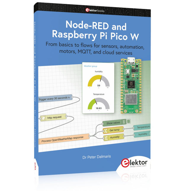
Elektor Publishing Node-RED and Raspberry Pi Pico W
From basics to flows for sensors, automation, motors, MQTT, and cloud services This book is a learning guide and a reference. Use it to learn Node-RED, Raspberry Pi Pico W, and MicroPython, and add these state-of-the-art tools to your technology toolkit. It will introduce you to virtual machines, Docker, and MySQL in support of IoT projects based on Node-RED and the Raspberry Pi Pico W. This book combines several elements into a platform that powers the development of modern Internet of Things applications. These elements are a flow-based server, a WiFi-enabled microcontroller, a high-level programming language, and a deployment technology. Combining these elements gives you the tools you need to create automation systems at any scale. From home automation to industrial automation, this book will help you get started. Node-RED is an open-source flow-based development tool that makes it easy to wire together devices, APIs, and online services. Drag and drop nodes to create a flowchart that turns on your lights at sunset or sends you an email when a sensor detects movement. Raspberry Pi Pico W is a version of the Raspberry Pi Pico with added 802.11n Wi-Fi capability. It is an ideal device for physical computing tasks and an excellent match to the Node-RED. Quick book facts Project-based learning approach. Assumes no prior knowledge of flow-based programming tools. Learn to use essential infrastructure tools in your projects, such as virtual machines, Docker, MySQL and useful web APIs such as Google Sheets and OpenWeatherMap. Dozens of mini-projects supported by photographs, wiring schematics, and source code. Get these from the book GitHub repository. Step-by-step instructions on everything. All experiments are based on the Raspberry Pi Pico W. A Wi-Fi network is required for all projects. Hardware (including the Raspberry Pi Pico W) is available as a kit. Downloads GitHub
€ 49,95
Members: € 44,96


-
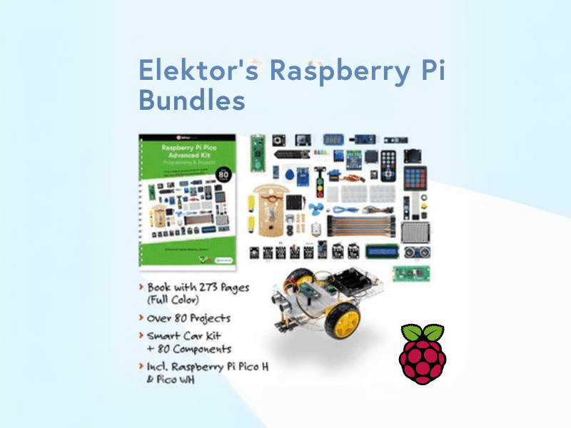
, by Lobna Belarbi Elektor’s Raspberry Pi Bundles: From Beginner-Friendly to Advanced Kits
Find the Perfect Raspberry Pi Bundle for Your Skill Level Whether you're a beginner eager to explore the world of Raspberry Pi or an advanced...
