The Elektor Zener Diode Tester is essentially a constant-current source that can be switched in steps from 1 to 50 mA. It can be used to test Z-diodes up to a maximum of 54 V. Thanks to a 60-V step-up converter, the device can be powered by the usual 5 to 12 V.
The principle of this tester is straightforward. A Z-diode or other DUT (device under test, such as an LED) is biased by an adjustable current source. The voltage across the DUT can be measured with a multimeter. The voltage of most (small) Z-diodes is specified at a current of 5 mA. Depending on the application, the voltage at other currents can also be of interest. That is why six current settings are available: 1, 2, 5, 10, 20, and 50 mA. LEDs are often specified at a current of 20 mA.
What can be tested is:
Whether a Z-diode is defective (short circuit or high impedance).
Whether a Z-diode exhibits the correct Z-voltage.
How a Z-voltage changes with different currents.
What exact voltage is present at an integrated voltage reference.
Whether LEDs in a series chain differ in brightness (hence the 20 mA current).
What the current gain is for different base currents in (power) transistors.
The kit contains all parts listed in the bill of materials including PCB and enclosure.
Specifications
Supply voltage
5…12 V/2 A (USB-C)
Supply current (Itest = 50 mA)
1.1 A @ 5 V / 412 mA @ 12 V
Selectable currents
1, 2, 5, 10, 20, and 50 mA
Max. test voltage
>54 V @ Itest ≥1 mA
Max. output voltage
60 V @ Itest = 0 mA
Voltage limit at 5 V
4.5 V @ Itest = 1 mA / 5.18 V @ Itest = 50 mA
Enclosure dimensions
110 x 82 x 44 mm
PCB size
105.4 x 67.3 mm
Connections
4 mm banana sockets for multimeter
2 mm banana sockets for test clips
USB-C socket for power supply
Included
Resistors
R1 = 3.3 kΩ, 600 mW, 1%
R2 = 0.15 Ω, 1 W, 5%, LS 12.7 mm, ø 3.5 mm
R3, R8 = 180 Ω, 600 mW, 1%
R4, R6, R16 = 1 kΩ, 600 mW, 1%
R5, R19 = 47 kΩ, 600 mW, 1%
R7 = 3.9 kΩ, 1 W, 5%, LS 12.7 mm, ø 3.5 mm
R9, R10, R12 = 10 kΩ, 600 mW, 1%
R11, R13 = 100 Ω, 600 mW 1%
R14 = 249 Ω, 600 mW, 1%
R15 = 499 Ω, 600 mW, 1%
R17 = 2.49 kΩ, 250 mW, 1%
R18 = 4.99 kΩ, 250 mW, 1%
Capacitors
C1 = 470 uF / 35 V, 20%, Ir = 1.86 A, ø 12.5 mm, LS 5 mm, ESR = 0.038 Ω (Panasonic EEUTP1V471)
C2 = 1 uF / 100 V, 10%, X7R, LS 5 mm
C3 = 2.2 nF / 50 V, 10%, X7R, LS 5 mm
C4, C7 = 100 nF / 100 V, 10%, X7R, LS 5 mm
C5 = 100 uF / 100 V, 20%, ø 14 mm max., LS 5 mm
C6 = 1 nF / 100 V, 10%, X7R, LS 5 mm
Inductor
L1 = 100 uH, Irms = 2.4 A, Isat = 3.5 A, 0.09 Ω, radial, pitch 2.5/5/10 mm, ø 14 mm max. (Kemet SBC8-101-242)
Semiconductors
D1 = MUR120G, DO-41
D2, D4 = STPS3150RL, DO-201AD
D3 = Z-diode, 18 V, 1.3 W (BZX85C18)
D5 = Z-diode, 5.1 V, 0.5 W (1N5231B)
LED1 = LED in pushbutton S1
LED2 = LED, green, 3 mm
IC1 = MC34063, DIP-8
IC2 = LM4040BIZ-5.0/NOPB, TO-92 (TO-226AA-3)
IC3 = TL051CP, DIP-8
T1 = BC327.25, TO-92
T2 = STP40NF10L, TO-220
T3 = IRF9510PBF, TO-220
T4 = 2N7000, TO-92
Others
K1, K2, S1, S3 = 2-way screw terminal block, LS 3.5 mm, max. 1.5 mm²
connected to K1 = USB-C socket, 30 V/3 A, chassis mounted, wired, 9 x 16 mm
connected to K2 = Banana Connector, 2 mm, Socket, 60 VDC, Panel Mount, red (Multicomp 24.102.1)
connected to K2 = Banana Connector, 2 mm, Socket, 60 VDC, Panel Mount, black (Multicomp 24.102.2)
Test clip, red, 30 VAC/60 VDC (Hirschmann 931467101)
Test clip, black, 30 VAC/60 VDC (Hirschmann 931467100)
S1 = Pushbutton, panel mount, SPST-NO, 30 DC/100 mA, with red LED
S2 = Rotary Switch, 6 position, 2 pole, 30°, 250 V/150 mA
S3 = Toggle switch, panel mount, SPDT, solder lugs, 28 VDC
T2, T3 = Heat sink, 15°C/W, FK 214 SA-CB
Enclosure Hammond 1591XXSSBK, ABS, 110 x 82 x 44 mm
Knob for S2, round shaft 6 mm, ø 21 mm, with indicator line (Multicomp CP-LB21-6-6D)
4 x Self-tapping screw #4-1/4", carbon steel, pan head
Banana plug, red, 2 mm, 60 VDC (Multicomp 25.205.1)
Banana plug, black, 2 mm, 60 VDC (Multicomp 25.205.2)
Banana socket, black 4 mm, panel mount
Banana socket, red 4 mm, panel mount
for LED1, LED2 = Pin header, 1 x 2, vertical, pitch 2.54 mm
for LED1, LED2 = Pin socket, 1 x 2, vertical, pitch 2.54 mm
for T2, T3 = M3 screw, 10 mm, steel, pan head
2 x M3 washer, plain, steel
4 x M3 nut
for IC1, IC3 = DIP-8 socket
Wire, black, 0.25 mm² (24 AWG), stranded 14 x 0.15 mm, 1 m
Wire, red, 0.25 mm² (24 AWG), stranded 14 x 0.15 mm, 1 m
PCB 250772-1 v1.1
Links
Article
Elektor Labs
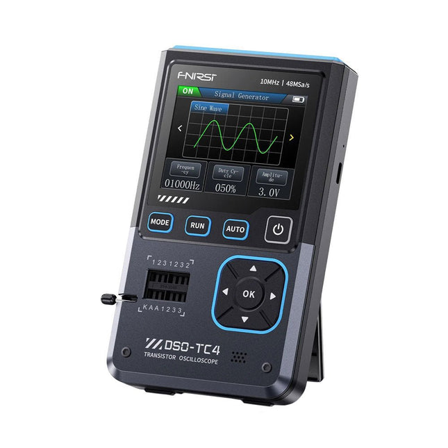
The FNIRDSI DSO-TC4 is a multifunctional transistor oscilloscope that is both comprehensive and practical. It is designed for use in maintenance and R&D applications, integrating an oscilloscope, transistor tester, and signal generator into a single device.
Features
Equipped with a 2.8-inch TFT color screen for a clear and intuitive display
Built-in high-capacity rechargeable lithium battery (1500 mAh) with a standby time of up to 4 hours
Compact and lightweight, ideal for mobile use
Specifications
Oscilloscope
Analog Bandwidth
10 MHz
Real-Time Sampling Rate
48 MSa/s
Input Impedance
1 MΩ
Coupling Mode
AC/DC
Test Voltage Range
1:1 Probe: 80 Vpp (+40 V)
10:1 Probe: 800 Vpp (+400 V)
Vertical Sensitivity
10 mV/div~10 V/div (X1 range)
Vertical Displacement
Adjustable with indication
Time Base Range
50ns~20s
Trigger Mode
Auto/Normal/Single
Trigger Type
Rising edge, Falling edge
Trigger Level
Adjustable with indication
Waveform Freeze
Yes (HOLD function)
Automatic Measurement
Max, Min, Avg, RMS, Vpp, Frequency, Cycle, Duty Cycle
Component Tester
Transistor
Amplification factor "hfe"; Base-Emitter voltage "Ube", Ic/Ie, Collector-Emitter reverse leakage current "Iceo", Ices, Forward voltage drop of protection diode "Uf"
Diode
Forward voltage drop <5 V (Forward voltage drop, Junction capacitance, Reverse leakage current)
Zener Diode
0.01~32 V
Reverse Breakdown Voltage (K-A-A Test Area)
Field-Effect Transistor (FET)
JFET: Gate capacitance "Cg", Drain current Id under "Vgs", Forward voltage drop of protection diode "Uf"
IGBT: Drain current Id under Vgs, Forward voltage drop of protection diode Uf
MIOSTET: Threshold voltage "Vt", Gate capacitance "Cg", Drain-Source resistance "Rds", Forward voltage drop of protection diode "Uf"
Unidirectional SCR
Trigger voltage <5V, Gate level (Gate voltage)
Bidirectional SCR
Trigger current <6mA (Gate voltage)
Capacitor
25pF~100mF, Capacitance value, Loss factor "Vloss"
Resistor
0.01Ω~50MΩ
Inductor
10μH~1000μH, DC resistance
DS18B20
Temperature sensor, Pins: GND, DQ, VDD
DHT11
Temperature and humidity sensor, Pins: VDD, DATA, GND
Signal Generator
Output Waveform
Supports 13 waveform outputs
Waveform Frequency
0-50 KHz
Square Wave Duty Cycle
0-100%
Waveform Amplitude
0.1-3.0 V
General
Display
2.8-inch TFT color screen
Backlight
Brightness adjustable
Power Supply
USB-C (5 V/1 A)
Battery
3.7 V/1500 mAh
Languages
English, German, Spanish, Portuguese, Russian, Chinese, Japanese, Korean
Dimensions
90 x 142 x 27.5 mm
Weight
186 g
Included
1x FNIRSI DSO-TC4 (3-in-1) Oscilloscope (10 MHz)
1x P6100 Oscilloscope probes (10X)
1x Alligator clip probe
3x Test hooks
1x Adapter
1x USB-C charging cable
1x Manual
Downloads
Manual
Firmware V0.0.7 (+V1.0.9)
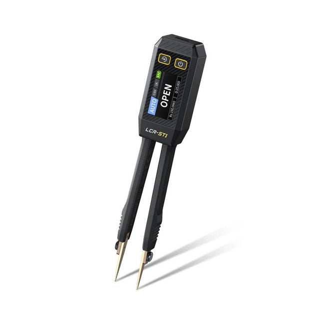
The FNIRSI LCR-ST1 is a compact, multifunctional, and smart LCR tester that supports automatic measurements of resistance, capacitance, inductance, diode testing, and continuity.
Its 1.14-inch color display combined with a convenient magnetic adsorption function enhances ease of use, while the built-in 250 mAh lithium battery ensures long-lasting performance. The device supports three frequency ranges (100 Hz, 1 kHz and 10 kHz) and offers 0.3 V and 0.6 V RMS test levels for versatile testing applications.
The unique tweezer-shaped design of the LCR-ST1 is ideal for delicate tasks in confined spaces and enables fast and accurate testing of electronic components. Its light weight and portable design make it an invaluable tool for both field and laboratory use.
Whether you are an experienced engineer or just starting out in electronics, the LCR-ST1 delivers reliable and accurate measurement results, allowing you to complete your tasks with greater efficiency and precision.
Features
Offers 3 test frequencies (100 Hz, 1 kHz, 10 kHz) and 2 test voltage levels.
Features automatic component identification for faster and more reliable measurements.
High-resolution 1.14-inch color display for clear readouts.
Supports automatic data recording and storage.
The tweezer tips are made from gold-plated brass for enhanced durability and conductivity.
Specifications
Resistance Range
10 mΩ – 10 MΩ
Capacitance Range
1 pF – 22 mF
Inductance Range
1 μh – 10 H
Diode
On voltage 0.7 V
Frequency Test
100 Hz, 1k Hz, 10 KHz
Level Test
0.3 V, 0.6 V RMS
Parameter Display
ESR, D value, Q value, Z value, X value
Display
1.14" HD color screen
Charging Interface
USB-C, 5 V/1 A
Power Supply
Built-in 250 mAh lithium battery
Auto Recognition Measurement
Yes
Replaceable Tweezer Head
Yes
Auto Shutdown
Yes
Data Hold
Yes
History Record
Connect to PC to view and export
Dimensions
28 x 19 x 150 mm
Weight
41 g
Included
1x LCR-ST1 SMD Tweezers
2x Hook Tips
1x Magnetic Patch
1x USB cable
1x Tool bag
1x Manual
Downloads
Manual
Firmware V1.6
The FNIRSI HRM-10 is a portable, high-precision battery internal resistance and voltage tester. This device offers true four-wire measurement and is designed for both accuracy and ease of use. It automatically measures internal resistance and voltage values simultaneously, displaying the results on its HD color screen. Users have the option to manually adjust voltage and resistance ranges to suit their needs. The device also includes a sorting mode that automatically filters the good and bad batteries based on user-set thresholds. Additionally, it supports the storage of historical data and allows for exporting measurement records in table format.
Features
High Measurement Accuracy
Tabular Data Export
Auto-Evaluate Measurement Results
8 Threshold Settings
HD Color Screen
Folding Stand
1000 mAh Lithium Battery
Specifications
Voltage
Resistance
Measuring range
0-100 V (DC)
0-200 Ω
Accuracy
±0.5%
±0.5%
Gear
Automatic, 1 V, 10 V, 100 V
Automatic, 20 mΩ, 200 mΩ, 2 Ω, 20 Ω, 200 Ω
Instrument test signal frequency
1 Khz (AC)
Rechargeable
USB-C (5 V/1 A)
Built-in battery
1000 mAh lithium battery
User calibration
Yes
Sorting mode
Yes
History record
Yes
Recorded data export
Yes
Working environment
–10°C to +45°C, relative humidity <80%
Storage environment
–20°C to +80°C, relative humidity <80%
Dimensions
158.7 x 80.5 x 28.4 mm
Weight
225 g
Included
1x FNIRSI HRM-10 Internal Resistance Tester
1x Clip Test Line
1x USB-C data cable
1x Manual
Downloads
Manual
Firmware V0.3
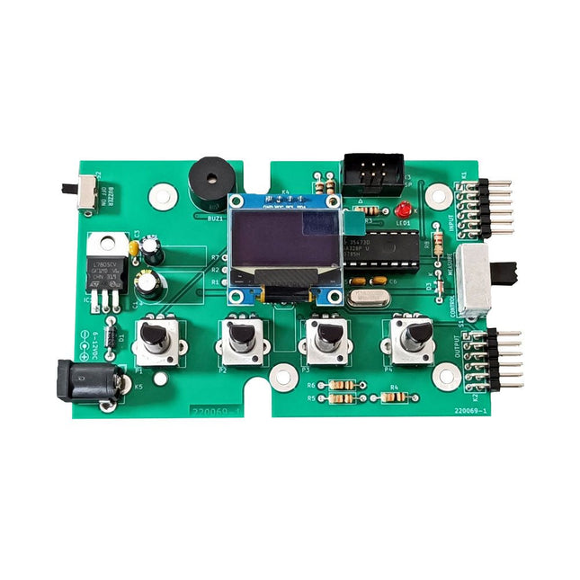
The Elektor Super Servo Tester can control servos and measure servo signals. It can test up to four servo channels at the same time.
The Super Servo Tester comes as a kit. All the parts required to assemble the Super Servo Tester are included in the kit. Assembling the kit requires basic soldering skills. The microcontroller is already programmed.
The Super Servo Tester features two operating modes: Control/Manual and Measure/Inputs.
In Control/Manual mode the Super Servo Tester generates control signals on its outputs for up to four servos or for the flight controller or ESC. The signals are controlled by the four potentiometers.
In Measure/Inputs the Super Servo Tester measures the servo signals connected to its inputs. These signals may come from for instance an ESC, a flight controller, or the receiver or another device. The signals are also routed to the outputs to control the servos or the flight controller or ESC. The results are shown on the display.
Specifications
Operating modes
Control/Manual & Measure/Inputs
Channels
3
Servo signal inputs
4
Servo signal outputs
4
Alarm
Buzzer & LED
Display
0.96' OLED (128 x 32 pixels)
Input voltage on K5
7-12 VDC
Input voltage on K1
5-7.5 VDC
Input current
30 mA (9 VDC on K5, nothing connected to K1 and K2)
Dimensions
113 x 66 x 25 mm
Weight
60 g
Included
Resistors (0.25 W)
R1, R3
1 kΩ, 5%
R2, R4, R5, R6, R7, R9, R10
10 kΩ, 5%
R8
22 Ω, 5%
P1, P2, P3, P4
10 kΩ, lin/B, vertical potentiometer
Capacitors
C1
100 µF 16 V
C2
10 µF 25 V
C3, C4, C7
100 nF
C5, C6
22 pF
Semiconductors
D1
1N5817
D2
LM385Z-2.5
D3
BZX79-C5V1
IC1
7805
IC2
ATmega328P-PU, programmed
LED1
LED, 3 mm, red
T1
2N7000
Miscellaneous
BUZ1
Piezo buzzer with oscillator
K1, K2
2-row, 12-way pinheader, 90°
K5
Barrel jack
K4
1-row, 4-way pin socket
K3
2-row, 6-way boxed pinheader
S1
Slide switch DPDT
S2
Slide switch SPDT
X1
Crystal, 16 MHz
28-way DIP socket for IC2
Elektor PCB
OLED display, 0.96', 128 x 32 pixels, 4-pin I²C interface
Links
Elektor Magazine
Elektor Labs
The OWON HDS2202s is a portable 3-in-1 multifunctional tester, which can be used as a 2-ch oscilloscope with a bandwidth of 200 MHz, multimeter and signal generator. It features a high-contrast 3.5-inch color display suitable for outdoor facility maintenance, rapid on-site measurement, automobile maintenance, power detection. etc. Features Oscilloscope + multimeter + waveform generator, multifunction in one 3.5-inch high-resolution, high-contrast color LCD display, suitable for outdoor use 18650 lithium battery, can work continuously for 3-6 hours USB Type-C interface, support power bank, support PC software connection Self-calibration function SCPI supported, facilitate secondary development Specifications Bandwidth 200 MHz Channels 2-ch Oscilloscope + 1-ch Generator Sample Rate 1 GSa/s Acquisition Model Normal, Peak detect Record Length 8K Display 3.5-inch LCD Waveform Refresh Rate 10,000 wfrms/s Input Coupling DC, AC, and Ground Input Impedance 1 MΩ ±2%, in parallel with 16pF ±10pF Probe Attenuation Factors 1X,10X,100X,1000X,10000X Max. input Voltage 400 V (DC+AC, PK-PK, 1MΩ input impedance) (10:1 probe attenuation) Bandwidth Limit (typical) 20 MHz Horizontal Scale 2ns/div - 1000s/div, step by 1 - 2 - 5 Vertical Sensitivity 10mV/div - 10V/div Vertical Resolution 8 bits Trigger Type Edge Trigger Modes Auto, Normal, single Automatic Measurement Frequency, Period, Amplitude, Max, Min, Mean, PK-PK Cursor Measurement ΔV, ΔT, ΔT&ΔV between cursors Communication Interface USB Type-C Multimeter Specifications Max. Resolution 20,000 counts Testing Mode Voltage, Current, Resistance, Capacitance, Diode, and Continuity test Input Impedance 10 MΩ Max Input Voltage AC 750 V, DC 1000 V Max Input Current DC: 10 A, AC: 10 A Diode 0-2 V Waveform Generator Specifications Frequency Output Sine 0.1 Hz - 25 MHz Square 0.1 Hz - 5MHz Ramp 0.1 Hz - 1 MHz Pulse 0.1 Hz - 5 MHz Arbitrary 0.1 Hz - 5 MHz Sampling Rate 125 MSa/s Channel 1-ch Amplitude Range (high impedance) 20 mVpp - 5 Vpp Waveform Length 8K Vertical Resolution 14 bits Output Impedance 50Ω Included 1x OWON HDS2202s 1x Power adapter 1x USB cable 1x Passive probes 2x Crocodile clip cable 1x Set of multimeter probes (one red and one black) 1x User manual 1x Probe correction adjustment knife Downloads User Manual Specifications SCPI Protocol Quick Guide Software
The HDS242 is a portable 2-in-1 multifunctional tester, which can be used as a 2-ch oscilloscope and multimeter. It features a high-contrast 3.5-inch color display suitable for outdoor facility maintenance, rapid on-site measurement, automobile maintenance, power detection. etc.
Features
Oscilloscope + Multimeter
3.5-inch high-resolution, high-contrast color LCD display – suitable for outdoor use
18650 lithium battery – can work continuously for up to 6 hours
USB-C interface – support power bank and PC connection
Self-calibration function
SCPI supported – facilitate secondary development
Specifications
Oscilloscope
Bandwidth
40 MHz
Channels
2-ch Oscilloscope
Sample Rate
250 MSa/s
Acquisition Model
Normal, Peak detect
Record Length
8K
Display
3.5-inch LCD
Waveform Refresh Rate
10,000 wfrms/s
Input Coupling
DC, AC, and Ground
Input Impedance
1 MΩ ±2%, in parallel with 16pF ±10pF
Probe Attenuation Factors
1X, 10X, 100X, 1000X, 10000X
Max. Input Voltage
400 V (DC+AC, PK-PK, 1MΩ input impedance) (10:1 probe attenuation)
Bandwidth Limit (typical)
20 MHz
Horizontal Scale
5ns/div - 1000s/div, step by 1 - 2 - 52ns/div - 1000s/div, step by 1 - 2 - 55ns/div - 1000s/div, step by 1 - 2 - 52ns/div - 1000s/div, step by 1 - 2 - 5
Vertical Sensitivity
10mV/div - 10V/div
Vertical Resolution
8 bits
Trigger Type
Edge
Trigger Modes
Auto, Normal, single
Automatic Measurement
Frequency, Period, Amplitude, Max, Min, Mean, PK-PK
Cursor Measurement
ΔV, ΔT, ΔT & ΔV between cursors
Multimeter
Max. Resolution
20,000 counts
Testing Mode
Voltage, Current, Resistance, Capacitance, Diode, and Continuity test
Input Impedance
10 MΩ
Max Input Voltage
AC: 750 V | DC: 1000 V
Max Input Current
DC: 10 A | AC: 10 A
Diode
0-2 V
Other
Connectivity
USB Type-C
Dimensions
198 x 96 x 38 mm (7.68 x 3.74 x 1.5')
Weight
600 g (without batteries)
Included
1x OWON HDS242 Oscilloscope
1x Soft Bag
1x Probe
1x Power Cord
1x Probe Adjust
1x USB Cable
1x Power Adapter
1x Pair of Multimeter Probe Leads (red one and black one)
1x Pair of Oscilloscope Probe Leads (BNC to Alligator Clip)
1x User Manual (English)
Downloads
User Manual
SCPI Protocol
Quick Guide
PC Software
The OWON HDS2102s is a portable 3-in-1 multifunctional tester, which can be used as a 2-ch oscilloscope with a bandwidth of 100 MHz, multimeter and signal generator. It features a high-contrast 3.5-inch color display suitable for outdoor facility maintenance, rapid on-site measurement, automobile maintenance, power detection. etc.Features
Oscilloscope + multimeter + waveform generator, multifunction in one
3.5-inch high-resolution, high-contrast color LCD display, suitable for outdoor use
18650 lithium battery, can work continuously for 3-6 hours
USB Type-C interface, support power bank, support PC software connection
Self-calibration function
SCPI supported, facilitate secondary development
Specifications
Bandwidth
100 MHz
Channels
2-ch Oscilloscope + 1-ch Generator
Sample Rate
500 MSa/s
Acquisition Model
Normal, Peak detect
Record Length
8K
Display
3.5-inch LCD
Waveform Refresh Rate
10,000 wfrms/s
Input Coupling
DC, AC, and Ground
Input Impedance
1 MΩ ±2%, in parallel with 16pF ±10pF
Probe Attenuation Factors
1X,10X,100X,1000X,10000X
Max. input Voltage
400 V (DC+AC, PK-PK, 1MΩ input impedance) (10:1 probe attenuation)
Bandwidth Limit (typical)
20 MHz
Horizontal Scale
2ns/div - 1000s/div, step by 1 - 2 - 5
Vertical Sensitivity
10mV/div - 10V/div
Vertical Resolution
8 bits
Trigger Type
Edge
Trigger Modes
Auto, Normal, single
Automatic Measurement
Frequency, Period, Amplitude, Max, Min, Mean, PK-PK
Cursor Measurement
ΔV, ΔT, ΔT&ΔV between cursors
Communication Interface
USB-C
Multimeter Specifications
Max. Resolution
20,000 counts
Testing Mode
Voltage, Current, Resistance, Capacitance, Diode, and Continuity test
Input Impedance
10 MΩ
Max Input Voltage
AC 750 V, DC 1000 V
Max Input Current
DC: 10 A, AC: 10 A
Diode
0-2 V
Waveform Generator Specifications
Frequency Output
Sine
0.1 Hz - 25 MHz
Square
0.1 Hz - 5MHz
Ramp
0.1 Hz - 1 MHz
Pulse
0.1 Hz - 5 MHz
Arbitrary
0.1 Hz - 5 MHz
Sampling Rate
125 MSa/s
Channel
1-ch
Amplitude Range (high impedance)
20 mVpp - 5 Vpp
Waveform Length
8K
Vertical Resolution
14 bits
Output Impedance
50Ω
Included
1x OWON HDS2102s
1x Power adapter
1x USB cable
1x Passive probes
2x Crocodile clip cable
1x Set of multimeter probes (one red and one black)
1x User manual
1x Probe correction adjustment knife
Downloads
User Manual
Specifications
SCPI Protocol
Quick Guide
Software
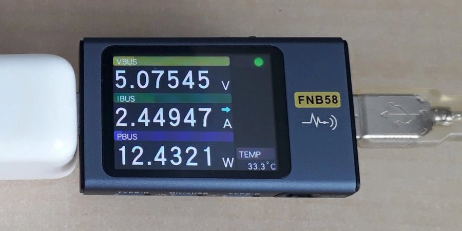
The FNIRSI FNB58 USB tester (with Bluetooth) is a comprehensive and very accurate USB voltage and current meter. It features a 2.0-inch full-color HD TFT display, built-in USB-A, micro USB and USB-C interface. With this device you can measure the power supply or power consumption of products or the charging power of cell phones and power supplies. You can also determine the fast charging protocol of chargers.
Features
USB-A and USB-C interface
2.0" HD display
Data at a glance
Wide compatibility
Ultra-precise data detection
Play with fast charging technology
Automatic protocol detection (PD2.0, 3.0, 3.1, PPS, QC2.0, 3.0, FCP, SCP, AFC, PE, DASH VOOC, SuperVOOC and more)
Simple user interface, easy to operate
4 function curve displays (real-time voltage and current curve, offline curve recording, D+/D- voltage curve, high-speed power supply ripple measurement)
Cable detection
10 groups of energy recording battery capacity calculation
PC connectivity for data logging and firmware updates
Bluetooth app for Android devices
Specifications
Voltage range
4-28 V
Current range
0-7 A
Power range
0-120 W
Load equivalent internal resistance
0-9999.9 Ω
D+/D- voltage
0-3.3 V
Capacity
0-9999.99 Ah
Power consumption
0-9999.99 Wh
Cable resistance
0-9999.9 Ω
Interfaces
micro USB, USB-A, USB-C
Dimensions
42 x 13 x 82 mm
Downloads
Manual
Firmware V0.68
,
by Jean-François Simon
Fnirsi FNB58 USB Tester (Review)
The Fnirsi FNB58 is a versatile USB tester capable of performing a wide array of voltage, current, and energy measurements, as well as supporting numerous...