Raspberry Pi Accessories
-
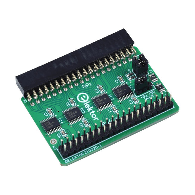
Elektor Labs Elektor Raspberry Pi Buffer Board
When you experiment with the Raspberry Pi on a regular basis and you connect a variety of external hardware to the GPIO port via the header you may well have caused some damage in the past. The Elektor Raspberry Pi Buffer Board is there to prevent this! The board is compatible with Raspberry Pi Zero, Zero 2 (W), 3, 4, 5, 400 and 500. All 26 GPIOs are buffered with bi-directional voltage translators to protect the Raspberry Pi when experimenting with new circuits. The PCB is intended to be inserted in the back of Raspberry Pi 400/500. The connector to connect to the Raspberry Pi is a right angled 40-way receptacle (2x20). The PCB is only a fraction wider. A 40-way flat cable with appropriate 2x20 headers can be connected to the buffer output header to experiment for instance with a circuit on a breadboard or PCB. The circuit uses 4x TXS0108E ICs by Texas Instruments. The PCB can also be put upright on a Raspberry Pi. Downloads Schematics Layout
€ 34,95€ 29,95
Best Price
-
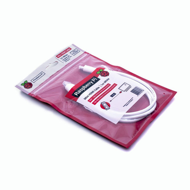
Raspberry Pi Foundation Official Mini-HDMI Cable for Raspberry Pi Zero
The official Raspberry Pi mini-HDMI to HDMI (A/M) cable designed for all Raspberry Pi Zero models. 19-pin HDMI Type D(M) to 19-pin HDMI Type A(M) 1 m cable (white) Nickel-plated plugs 4Kp60 compliant RoHS compliant 3 Mohm 300 VDC insulation, withstands 300 VDC for 0.1s
€ 3,95€ 1,95
Best Price
-
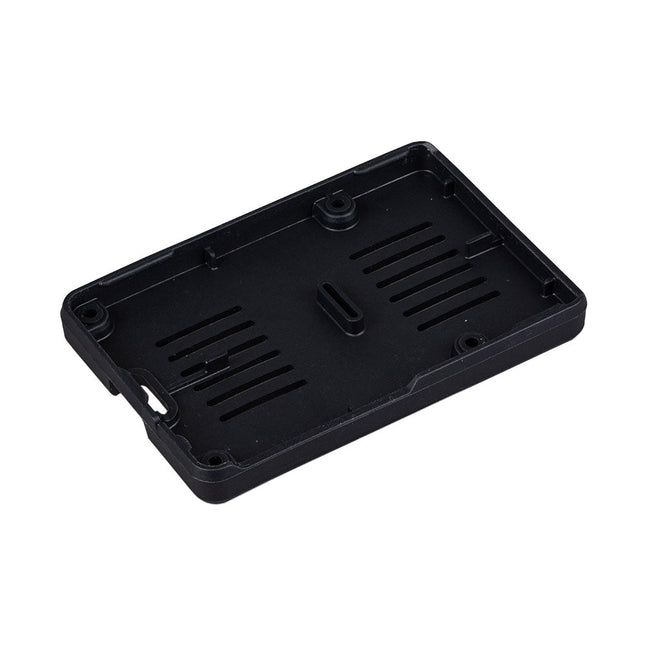
Raspberry Pi Foundation Bumper for Raspberry Pi 5
The Raspberry Pi Bumper is a snap-on silicone cover that protects the bottom and edges of the Raspberry Pi 5. Features One-piece flexible silicone rubber bumper Enables easy access to the power button Mounting holes remain accessible underneath the bumper Downloads Datasheet
€ 3,50€ 1,40
Best Price


