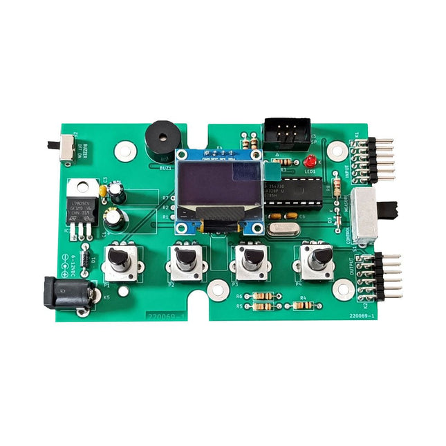
The Elektor Super Servo Tester can control servos and measure servo signals. It can test up to four servo channels at the same time.
The Super Servo Tester comes as a kit. All the parts required to assemble the Super Servo Tester are included in the kit. Assembling the kit requires basic soldering skills. The microcontroller is already programmed.
The Super Servo Tester features two operating modes: Control/Manual and Measure/Inputs.
In Control/Manual mode the Super Servo Tester generates control signals on its outputs for up to four servos or for the flight controller or ESC. The signals are controlled by the four potentiometers.
In Measure/Inputs the Super Servo Tester measures the servo signals connected to its inputs. These signals may come from for instance an ESC, a flight controller, or the receiver or another device. The signals are also routed to the outputs to control the servos or the flight controller or ESC. The results are shown on the display.
Specifications
Operating modes
Control/Manual & Measure/Inputs
Channels
3
Servo signal inputs
4
Servo signal outputs
4
Alarm
Buzzer & LED
Display
0.96' OLED (128 x 32 pixels)
Input voltage on K5
7-12 VDC
Input voltage on K1
5-7.5 VDC
Input current
30 mA (9 VDC on K5, nothing connected to K1 and K2)
Dimensions
113 x 66 x 25 mm
Weight
60 g
Included
Resistors (0.25 W)
R1, R3
1 kΩ, 5%
R2, R4, R5, R6, R7, R9, R10
10 kΩ, 5%
R8
22 Ω, 5%
P1, P2, P3, P4
10 kΩ, lin/B, vertical potentiometer
Capacitors
C1
100 µF 16 V
C2
10 µF 25 V
C3, C4, C7
100 nF
C5, C6
22 pF
Semiconductors
D1
1N5817
D2
LM385Z-2.5
D3
BZX79-C5V1
IC1
7805
IC2
ATmega328P-PU, programmed
LED1
LED, 3 mm, red
T1
2N7000
Miscellaneous
BUZ1
Piezo buzzer with oscillator
K1, K2
2-row, 12-way pinheader, 90°
K5
Barrel jack
K4
1-row, 4-way pin socket
K3
2-row, 6-way boxed pinheader
S1
Slide switch DPDT
S2
Slide switch SPDT
X1
Crystal, 16 MHz
28-way DIP socket for IC2
Elektor PCB
OLED display, 0.96', 128 x 32 pixels, 4-pin I²C interface
Links
Elektor Magazine
Elektor Labs
This board allows the Raspberry Pi Pico (connected via pin header) to drive two motors simultaneously with full forward, reverse & stop control, making it ideal for Pico controlled buggy projects. Alternatively, the board can be used to power a stepper motor. The board features the DRV8833 motor driver IC, which has built-in short circuit, over current and thermal protection.
The board has 4 external connections to GPIO pins and a 3 V and GND supply from the Pico. This allows for additional IO options for your buggy builds that can be read or controlled by the Pico. In addition there is an on/off switch and power status LED, allowing you to see at a glance if the board is powered up and save your batteries when your project is not in use.
To use the motor driver board, the Pico should have a soldered pin header and be inserted firmly into the connector. The board produces a regulated supply that is fed into the 40-way connector to power the Pico, removing the need to power the Pico directly. The motor driver board is powered via either screw terminals or a servo style connector.
Kitronik has developed a micro-python module and sample code to support the use of the Motor Driver board with the Pico. This code is available in the GitHub repo.
Features
A compact yet feature-packed board designed to sit at the heart of your Raspberry Pi Pico robot buggy projects.
The board can drive 2 motors simultaneously with full forward, reverse, and stop control.
It features the DRV8833 motor driver IC, which has built-in short circuit, over current and thermal protection.
Additionally, the board features an on/off switch and power status LED.
Power the board via a terminal block style connector.
The 3V and GND pins are also broken out, allowing external devices to be powered.
Code it with MicroPython via an editor such as the Thonny editor.
Dimensions: 63 mm (L) x 35 mm (W) x 11.6 mm (H)
Download
Datasheet
The MotoPi is an extension-board to control and use up to 16 PWM-controlled 5 V servo motors. The board can be additional powered by a voltage between 4.8 V and 6 V so a perfect supply is always guaranteed and even larger projects can be powered.
With the additional power supply and the integrated Analog-Digital-Converter, new possibilities can be reached. An additional power supply per motor is not required anymore because all connections (Voltage, Ground, Control) are directly connected to the board.
The control and the programing can be directly done, as usual, on the Raspberry Pi.
Specifications
Special features
16 Channels, own clock generator, Inkl. Analog Digital Converter
Input 1
Coaxial power connector 5.5 / 2.1 mm, 5 V / 6 A max
Input 2
Screw terminal, 4.8-6 V / 6 A max
Compatible with
Raspberry Pi A+, B+, 2B, 3B
Dimensions
65 x 56 x 24 mm
Scope of supply
Board, manual, fixing material
An adapter for connecting a servo meter with croc/alligator clips.
This is a handy little clip to connect a servo motor with 5.4 mm header socket using alligator clips. It is ideal for use with boards like the BBC micro:bit and Adafruit's Circuit Playground Express or Gemma.
Width: 27 mm
Height: 35 mm
Downloads
Datasheet