Measuring Tools

102 Products

  • Siglent SPD3303X - E DC Power Supply - Elektor

    Siglent Siglent SPD3303X-E 3-ch DC Power Supply (220 W)

    SPD3000X Series Linear Programmable DC Power Supply has a 4.3-inches TFT LCD display, Supports Programmability and Real Time Wave Display, bringing a new experience to users. It has three isolated outputs: two adjustable channels and one selectable channel from 2.5V, 3.3V, and 5V. It also has output short and overload protect function, and can be used in production and development. Features 3 independent controlled and isolated output, 32V/3.2A×2, 2.5V/3.3V/5V/3.2A×1, total 220W. 5 digits Voltage, 4digits Current Display, Minimum Resolution: 10mV/10mA. Supports panel timing output functions. 4.3 inch true color TFT LCD 480x272 pixel display. 3 kinds of output modes: independent, series, parallel. 100V/120V/220V/230V compatible design to meet the needs of different power grids. Intelligent temperature-controlled fan, effectively reducing noise. Clear graphical interface, with the waveform display function Internal 5 groups of system parameter save/recall, supports data storage space expansion. Provides PC software: Easypower, supports SCPI, LabVIEW driver. High-resolution and high-precision output The highest resolution of 10mV/10mA, provides excellent setting and read back accuracy. This ensures accurate output even with very with small changes in voltage or current. This is impossible for a low resolution power supply. Series/parallel/independent mode function Series and parallel function allows two channels combined into one output with more power output capability, extending the application range. Each of 3 channels power can be turned on or off independently and also can be turned all on or all off. Panel displays the timing output Through the panel operation, 5 groups of timing settings and output control can be displayed, which provides users a simple power programming function. Also a connection can be made with Siglent’s EasyPower PC software providing a full range of communication and control requirements. Save/Recall setting parameters SPD3000X series programmable power supply can save or recall 5 groups of setting parameter in internal storage, also supports external storage expansion. You can easily obtain the settings you needed.

    € 436,51

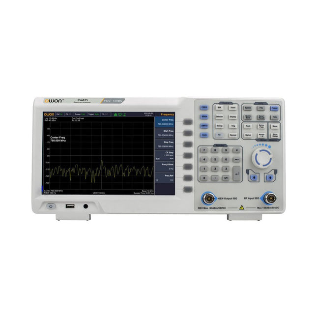
  • OWON XSA815 - TG Spectrum Analyzer (9 kHz – 1.5 GHz) - Elektor

    OWON OWON XSA815-TG Spectrum Analyzer (9 kHz – 1.5 GHz)

    The OWON XSA815-TG (9 kHz-1.5 GHz) is a cost effective spectrum analyzer with tracking generator included and a frequency resolutions of 1 Hz. Features Frequency Range from 9 kHz to 1.500009 GHz 9-inch display 9 kHz to 1 MHz -95 dBm Displayed Average Noise Level, 1 MHz to 500 MHz 140 dBm (Typical), <-130 dBm Phase Noise -10 kHz <-80 dBc/Hz 100 kHz <-100 dBc/Hz 1 MHz <-115 dBc/Hz Resolution Bandwidth (-3 dB): 1 Hz to 1 MHz, in 1-3-5-10 sequence Tracking Generator Kit: 100 kHz to 1.500009 GHz Specifications Frequency Range 9 kHz to 500.009 MHz Frequency Resolution 1 Hz Frequency Span 9 kHz to 1.500009 GHz Span Range 0 Hz, 100 Hz to max frequency of instrument Span Uncertainty ±span / (sweep points-1) SSB Phase Noise (20°C to 30°C, fc=1 GHz) Carrier Offset 10 kHz <-80 dBc/Hz | 100 kHz <-100 dBc/Hz | 1 MHz <-115 dBc/Hz Resolution Bandwidth (-3 dB) 1 Hz to 1 MHz, in 1-3-5-10 sequence RBW Accuracy <5% typical Resolution Filter Shape Factor (60 dB: 3 dB) <5 typical Video Bandwidth (-3 dB) 10 Hz to 1 MHz, in 1-3-5-10 sequence Amplitude measurement range DANL to +10 dBm, 100 kHz to 10 MHz, Preamp Off DANL to +20 dBm, 10 MHz to 1.5 GHz, Preamp Off Reference Level -80 dBm to +30 dBm, 0.01dB by step Preamp 20 dB, nominal, 100 kHz to 1.5 GHz Input Attenuator 0 to 40 dB, 1 dB by step Display Average Noise Level Input attenuation = 0 dB, RBW = VBW = 100 Hz, sample detector, trace average ≥ 50, 20°C to 30°C, input impedance = 50 Ω) Preamp Off 9 kHz to 1 MHz -95 dBm (Typical), <-88 dBm Preamp Off 1 MHz to 500 MHz -140 dBm (Typical), <-130 dBm Preamp On 100 kHz to 1 MHz -135 dBm (Typical), <-128 dBm Preamp On 1 MHz to 500 MHz -160 dBm (Typical),<-150 dBm Tracking Generator (optional) Frequency Range 100 kHz to 1.500009 GHz Output power level range -40 dBm to 0 dBm Output level resolution 1 dB Output flatness Relative to 50 MHz | ±3 dB Tracking generator spurious Harmonic spurious -30 dBc (Tracking generator output power -10 dBm) Non-harmonic spurious -40 dBc (Tracking generator output power -10 dBm) Tracking generator to input terminal isolation -60 dB (Tracking generator output power 0 dBm) Tracking generator to input terminal isolation -60 dB (Tracking generator output power 0 dBm) Tracking generator to input terminal isolation -60 dB (Tracking generator output power 0 dBm) Dimensions 375 x 185 x 120 mm Weight 3.7 kg Included 1x XSA815-TG 1x 220 V AC power cord 1x USB Cable 1x Quickstart guide Downloads Quick Guide Specifications

    € 907,50

  • Electron Plus SPA100 Source Picoammeter - Elektor

    Electron Plus Electron Plus SPA100 Source Picoammeter

    This highly sensitive source picoammeter is designed for measuring and logging very small currents down to the pA range – making it an ideal instrument for scientific and research applications, including physics, materials science and electron microscopy. Full-featured at an affordable price, the SPA100 combines sensitivity, accuracy and stability to allow users to measure low currents with high precision as well as conveniently source bias voltages for experimentation. SPA100 also doubles as an ultra-high resistance meter, measuring accurately into the teraohm range. The SPA100 connects to PC via USB and utilises the complimentary software SPA – enabling users to easily measure, graph and capture readings with timestamps and measurement stability information. Features Input: ±2 mA to ±200 pA in 8 ranges Accuracy and Resolution (2 Hz): ±2 mA range: ±0.1%, resolution <20 nA ±200 uA range: ±0.1%, resolution <2 nA ±20 uA range: ±0.2%, resolution <200 pA ±2 uA range: ±0.2%, resolution <20 pA ±200 nA range: ±0.5%, resolution <2 pA ±20 nA range: ±0.5%, resolution <200 fA ±2 nA range: ±1.0%, resolution <20 fA ±200 pA range: ±1.5%, resolution <2 fA Sample rate: 2 Hz (18 bit) or 10 Hz (16 bit) Adjustable filter: 1 sample to 64 samples Output voltage: -40 V to +40 V (in 1 V increments), output resistance 2.7 Kohms Resistance Measurement: ~1 Kohms to 40 Tohms (e.g 40 V source, 1 pA measure) Accuracy: >±0.5% 1 Mohm to 1 Tohm Powered via USB 2.0 (instrument uses up to 0.3 A when in-use) Included 1x SPA100 Source Picoammeter 1x USB cable Downloads Manual Software

    € 264,99

  • OWON DGE3062 2 - ch Arbitrary Waveform Generator (60 Mhz) - Elektor

    OWON OWON DGE3062 2-ch Arbitrary Waveform Generator (60 MHz)

    The OWON DGE3062 is a 14-bit function generator with a bandwidth of 60 MHz. It has 5 basic waveforms, 160 built-in arbitrary waveforms and the following comprehensive modulation functions: AM, FM, PM, PWM, FSK, 3FSK, 4FSK, PSK, ASK, BPSK, OSK, DSBAM, QPSK, SUM, sweep, Burst. Features Max. 60 MHz frequency output, 300 MSa/s Sample rate 14 bits Vertical Resolution, 100K Arb waveform length Comprehensive waveform output: 5 basic waveforms, and 160 built-in arbitrary waveforms Comprehensive modulation functions: AM, FM, PM, PWM, FSK, 3FSK, 4FSK, PSK, ASK, BPSK, OSK, DSBAM, QPSK, SUM, sweep, Burst SCPI and LabVIEW supported 3.6 inch LCD (480 x 272 pixels) Specifications Channel 2 Frequency Output 60 MHz Sample Rate 300 MSa/s Vertical Resolution 14 bits Waveform Standard Waveform Sine, square, pulse, ramp, noise Arbitrary Waveform Exponential rise, exponential fall, sin(x)/x, step wave, and others, total 160 built-in waveforms Frequency (resolution 1 μHz) Sine 1 μHz-60 MHz Square 1 μHz ~ 20 MHz Pulse 1 μHz ~ 20 MHz Ramp 1 μHz ~ 2 MHz Noise 20 MHz (-3 dB, typical) Arbitrary Waveform 1 μHz ~10 MHz Arbitrary Waveform Length 2 points – 100K points Sample Rate 300 MSa/s Amplitude Into 50Ω load 1mVpp ~ 10Vpp (≤10Hz), 1mVpp ~ 5Vpp (≤60 MHz) DC Offset Range (AD+DC ±(10 Vpk – Amplitude Vpp/2) high resistance±(5 Vpk – Amplitude Vpp/2) 50 Ω DC offset resolution 1 mV or 4 digits Load Impedance 50 Ω (typical) DC offset Accuracy ±(1% of |setting| + 1 mV + amplitude Vpp * 0.5%) Modulation Type AM,FM, PM, PWM, FSK, 3FSK, 4FSK, PSK, ASK, BPSK, OSK, DSB-AM, QPSK, SUM, Sweep, Burst Frequency Counter Function Frequency, period Frequency Range 100 MHz ~ 100 MHz Frequency Resolution 6 digits Input/Output Display 3.6” LCD Input mode External modulation input, external trigger input, external reference clock input/output Communication Interface USB Host, USB Device Mechanical specifications Dimensions (W x H x D) 200 x 92 x 157 mm Weight 0.8 kg Included 1x OWÒN DGE3062 Arbitrary Waveform Generator 1x Power Cord 1x Quick Guide 1x USB Cable 1x Q9 Cable 1x BNC to Alligator Clip Downloads Quick Guide Manual Software

    € 212,50

  • OWON SPS6051 Fanless DC Power Supply (150 W) - Elektor

    OWON OWON SPS6051 Fanless DC Power Supply (150 W)

    The OWON SPS6051 Fanless Programmable DC Power Supply (150 W) delivers ultra-quiet, high-precision performance with 10 mV/1 mA accuracy and advanced heat dissipation for long-term reliability. Featuring comprehensive protection, a USB interface with SCPI support for remote control, and a 2.8-inch TFT LCD screen, it is the perfect choice for laboratories, electronics testing, and research. Features Fanless design: Ultra-quiet operation, reducing vibration noise and minimizing the potential failure risks associated with traditional cooling fans. Excellent heat dissipation design: Ensures a controlled temperature rise, allowing long-term operation under full load conditions and extending internal component longevity. Lightweight and ultra-thin design. Output accuracy up to 10 mV/1 mA. Supports List waveform editing and output, with four memory shortcut parameters for quick and convenient access. Integrated protection features include overvoltage, overcurrent, overtemperature, and input undervoltage protection for enhanced safety. Built-in discharge circuit prevents residual high voltage risks when the power is turned off. USB communication interface with SCPI protocol support, enabling PC programming and remote control for simplified user management. 2.8-inch TFT LCD screen Specifications Model SPS6051 SPS3081 Rated Output (0°C-40°C) Voltage 0-61 V 0-31 V Current 0-5.1 A 0-8.1 A Power 150 W 120 W Load Regulation Voltage ≤30 mV Current ≤20 mA Power Regulation Voltage ≤30 mV Current ≤20 mA Setting Resolution Voltage 10 mV Current 1 mA Readback Resolution Voltage 10 mV Current 1 mA Seting Accuracy (25°C ±5°C) Voltage ≤0.05% ±20 mV ≤0.1% ±20 mV Current ≤0.05% ±20 mA ≤0.2% ±20 mA Readback Accuracy (25°C ±5°C) Current ≤0.05% ±20 mV ≤0.1% ±20 mV Voltage ≤0.05% ±20 mV ≤0.2% ±20 mA Ripple/Noise Voltage ≤30 mVp-p ≤30 mVp-p Voltage ≤4 mVrms ≤5 mVrms Current ≤10 mAp-p ≤30 mAp-p Output temperature coefficient (0°C-40°C) Voltage 100 ppm/°C Current 200 ppm/°C Readback temperature coefficient Voltage 100 ppm/°C Current 200 ppm/°C Response Time (50-100% rated load) ≤1.0 ms Storage 4 groups of data Working Temperature 0-40°C Display 2.8-inch color LCD display Interface USB Dimensions (W x H x D) 82 x 142 x 226 mm Weight 1.8 kg Included 1x OWON SPS6051 Power Supply 2x Test leads 1x Power cord 1x Manual Downloads Datasheet User Manual Programming Manual PC Software

    € 134,31

  • OWON P4603 DC Power Supply (180 W) - Elektor

    OWON OWON P4603 DC Power Supply (180 W)

    This OWON DC Power Supply has a small body and is easy to carry due to its light weight. Featuring a 3.7" TFT LCD display, it has a maximum output power of 180 W and a resolution of 1 mV/1 mA. Features Channel Single Channel Output Total Output Power 180 W Channel Output 0 - 60 V / 0 - 3 A × 1-CH Display 3.7' color LCD display Dimension 117 mm(L) × 194 mm(H) × 295 mm(D) Weight Approx. 5.8 kg Interface RS232 Specifications Rated Output (0 ℃ - 40 ℃) Voltage 0 - 60 V Current 3 A Load Regulation Voltage ≤ 0.01% + 3 mV Current ≤ 0.01% + 3 mA Power Regulation Voltage ≤ 0.01% + 3 mV Current ≤ 0.01% + 3 mA Setting Resolution Voltage 1 mV Current 1 mA Readback Resolution Voltage 1 mV Current 1 mA Setpoint accuracy (within 12 months) (25 ℃ ± 5 ℃) Voltage ≤ 0.03% + 10 mV Current ≤ 0.1% + 5 mA Readback Resolution (25 ℃ ± 5 ℃) Voltage ≤ 0.03% + 10 mV Current ≤ 0.1% + 5 mA Ripple/Noise (20 Hz - 20 MHz) Voltage (Vp-p) ≤ 4 mVp-p Voltage (Vrms) ≤ 1 mVrms Current (rms) ≤ 4 mArms Output temperature coefficient(0 ℃ - 40 ℃) Voltage ≤ 0.03% + 10 mV Current ≤ 0.1% + 5 mA Readback temperature coefficient Voltage ≤ 0.03% + 10 mV Current ≤ 0.1% + 5 mA Response Time 100 μs Storage 5 groups of data Working Temperature 0 - 40 ℃

    € 164,57

  • OWON SDS1104 4 - ch Oscilloscope (100 MHz) - Elektor

    OWON OWON SDS1104 4-ch Oscilloscope (100 MHz)

    The OWON SDS1104 oscilloscope is a practical choice for engineers, technicians, students, and hobbyists who need accurate signal analysis without the cost of high-end instruments. With its 100 MHz bandwidth and 1 GSa/s sampling rate, it reliably captures low- to mid-frequency signals, making it well suited for electronics development, troubleshooting, and educational use. Equipped with a 7-inch color TFT display, the SDS1104 provides clear waveform visualization, while automatic measurement functions and FFT analysis help users quickly evaluate frequency, voltage, and timing parameters. Advanced math operations, cursor measurements, and multiple trigger modes add further flexibility, making the oscilloscope a versatile tool for a wide range of testing scenarios. Specifications Bandwidth 100 MHz Sample Rate 1 GS/s Horizontal Scale (s/div) 5ns/div - 1000s/div, step by 1 - 2 - 5 Channel 4 Display 7" color LCD, 800 x 480 pixels Input Coupling DC, AC and GND Vertical Resolution (A/D) Vertical Resolution (A/D) Vertical Sensitivity 5mV/div - 5V/div (at input) Trigger Type Edge, Video Trigger Mode Auto, Normal and Single Waveform Math +, -, x, ÷, invert, FFT Fuse 2A, T class, 250 V Dimension (W x H x D) 301 x 152 x 70 mm Weight 1.1 kg Included 1x OWON SDS1104 Oscilloscope 1x Mains power cord 1x CD Rom 1x Quickstart Guide 1x USB Cable 4x Oscilloscope probe 1x Probe Adjust Downloads Datasheet Manual

    € 249,00

  • JOY-iT PS1440-C-Pro Programmable Laboratory Power Supply with RS485 (1440 W)

    JOY-iT JOY-iT PS1440-C-Pro Programmable Laboratory Power Supply with RS485 (1440 W)

    With the JOY-iT PS1440-C-Pro, you get a programmable laboratory power supply that delivers DC voltages ranging from 0.01 to 60 V and DC currents from 0.01 to 24 A at the voltage output. The intuitive control panel allows you to program, store, and recall up to 9 different DC voltage settings. You can also configure individual protection and limiting functions—such as overvoltage protection. All settings are easily adjusted via the keypad and/or rotary control and are clearly shown on the high-resolution 2.4" color display. For enhanced connectivity, the PS1440-C-Pro includes an RS485 interface for robust, long-distance communication. This makes it ideal for complex setups where signal stability, noise immunity, and reliable data transfer are critical. The included connector ensures a secure connection, improving the overall reliability and performance of your laboratory equipment setup. Features Complete device ready for immediate use RS485 interface Battery charging function Values can be entered conveniently via keypad Over current & over voltage protection adjustable Integrated RTC, NTC temperature sensor Included detailed documentation in English, German & French Specifications Input voltage 230 V Output voltage 060 V Output current 0-24 A Output power 0-1440 W Input voltage accuracy ±1% +5 digits Output voltage accuracy ±0.3% +3 digits Output current accuracy ±0.5% +5 digits Battery voltage ±0.5% +3 digits Input voltage measurement resolution 0.01 V Output voltage measurement resolution 0.01 V Current measurement resolution 0.01 V Battery voltage measurement resolution 0.01 V Response time in constant voltage mode 2 ms @ 0.1-5 A Load regulation in constant voltage mode ±0.1% +2 digits Load regulation in constant current mode ±0.1% +3 digits Measuring range electric charge 0-9999.99 Ah Measuring range energy 0-9999.99 Wh Statistical errors in electric charge & energy ±2% Output ripple 100 mV VPP @ 12 V150 mV VPP @ 24 V Sensor temperature detection range −10~100°C (0-200°F) Sensor temperature detection accuracy ±3°C (±6°F) Working mode Step-down operation Screen brightness setting Level 0-5, 6 levels in total Permissible working temperature −10~40°C (0-104°F) Dimensions 170 x 93 x 340 mm Included JOY-iT PS1440-C Power Supply 2-pin connector for RS485 interface Power cord Manual Downloads Datasheet MODBUS Protocol PC Software Driver for Windows

    € 499,00

    Members: € 449,10

  • Siglent SPD3303X DC Power Supply - Elektor

    Siglent Siglent SPD3303X 3-ch DC Power Supply (220 W)

    SPD3000X Series Linear Programmable DC Power Supply has a 4.3 inches TFT LCD display, Supports Programmability and Real Time Wave Display, bringing a new experience to users. It has three isolated outputs: two adjustable channels and one selectable channel from 2.5V, 3.3V, and 5V. It also has output short and overload protect function, and can be used in production and development. Features 3 independent controlled and isolated output, 32V/3.2A×2, 2.5V/3.3V/5V/3.2A×1, total 220W. 5 digits Voltage, 4 digits Current Display, Minimum Resolution: 1mV/1mA. Supports panel timing output functions. 4.3 inch true color TFT LCD 480x272 pixel display. 3 kinds of output modes: independent, series, parallel. 100V/120V/220V/230V compatible design to meet the needs of different power grids. Intelligent temperature-controlled fan, effectively reducing noise. Clear graphical interface, with the waveform display function Internal 5 groups of system parameter save/recall, supports data storage space expansion. Provides PC software: Easypower, supports SCPI, LabVIEW driver. High-resolution and high-precision output The highest resolution of 1mV/1mA, provides excellent setting and read back accuracy. This ensures accurate output even with very with small changes in voltage or current. This is impossible for a low resolution power supply. Series/parallel/independent mode function Series and parallel function allows two channels combined into one output with more power output capability, extending the application range. Each of 3 channels power can be turned on or off independently and also can be turned all on or all off. Panel displays the timing output Through the panel operation, 5 groups of timing settings and output control can be displayed, which provides users a simple power programming function. Also a connection can be made with Siglent’s EasyPower PC software providing a full range of communication and control requirements. Save/Recall setting parameters SPD3000X series programmable power supply can save or recall 5 groups of setting parameter in internal storage, also supports external storage expansion. You can easily obtain the settings you needed.

    € 600,50

  • Siglent SDG2042X Arbitrary Waveform Generator (40 MHz) - Elektor

    Siglent Siglent SDG2042X 2-ch Arbitrary Waveform Generator (40 MHz)

    Siglent's SDG2000X is a series of dual-channel function/arbitrary waveform generators with specifications of up to 120 MHz maximum bandwidth, 1.2 GSa/s sampling rate and 16-bit vertical resolution. The proprietary TrueArb & EasyPulse techniques help to solve the weaknesses inherent in traditional DDS generators when generating arbitrary, square and pulse waveforms. With advantages above, SDG2000X can provide users with a variety of high fidelity and low jitter signals, which can meet the growing requirements of complex and extensive applications. Features Dual-channel, 40 MHz bandwidth, 20Vpp maximum output amplitude, high fidelity output with 80dB dynamic range. High-performance sampling system with 1.2GSa/s sampling rate and 16-bit vertical resolution. No detail in your waveforms will be lost. Innovative TrueArb technology, based on a point-by-point architecture, supports any 8pts~8Mpts Arb waveform with a sampling rate in range of 1μSa/s~75MSa/s. Innovative EasyPulse technology, capable of generating lower jitter Square or Pulse waveforms, brings a wide range and extremely high precision in pulse width and rise/fall times adjustment. Plenty of analog and digital modulation types: AM, DSB-AM, FM, PM, FSK, ASK and PWM. Sweep and Burst functions. High precision Frequency Counter. Standard interfaces: USB Host, USB DeviceUSBTMC, LAN (VXI-11) Optional interface: GPIB. 4.3” touch screen display for easier operation. Specifications Maximum output frequency 40 MHz Output channels 2 Sampling rate 1.2 GSa/s (4X Interpolation) Wave length CH1: 16 Kpts, CH2: 512 Kpts Frequency resolution 1 μHz Vertical resolution 16 bit Standard interfaces Standard interfaces: USB Host, USB Device (USBTMC), LAN (VXI-11) High-performance Sampling System Benefiting from a 1.2GSa/s and 16-bit sampling system, SDG2000X achieves extremely high accuracy performance in both time domain and amplitude, which results in more accurately reconstructed waveforms and lower distortion. Innovative EasyPulse Technology When a Square/Pulse waveform is generated by DDS, there will be a one-clock-jitter if the sampling rate is not an integer-related multiple of the output frequency. SDG2000X EasyPulse technology successfully overcomes this weakness in DDS designs and helps to produce low jitter Square/Pulse waveforms. Innovative TrueArb Technology For arbitrary waveforms, TrueArb not only has all the advantages of traditional DDS, but also eliminates the probability that DDS may cause serious jitter and distortion. Easy controll with 4.3” Touch Screen Display and Arbitrary Waveform Software EasyWave The 4.3” touch screen display, makes operation much more convenient. And EasyWave is a powerful arbitrary waveform editing software that supports several ways to generate arbitrary waveform such as manual drawing, line-drawing, equation-drawing, coordinate-drawing, etc. It is quite convenient for users to edit their own arbitrary waveforms through EasyWave. Included Siglent SDG2042X Arbitrary Function Generator User Manual Guarantee Card CD (including EasyWave 1.0 computer software system) Power Cord USB Cable Quick Start Guide

    € 560,39

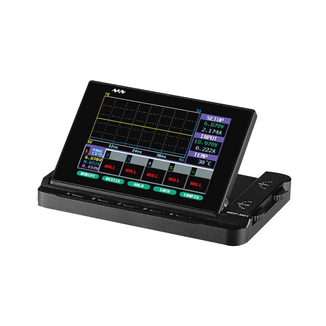
  • Miniware MDP - M01 Smart Digital Monitor - Elektor

    Miniware Miniware MDP-M01 Smart Digital Monitor

    MDP-M01 is a display control module equipped with a 2.8-inch TFT display screen, the screen can be turned 90 degrees, which is convenient for users to view data and waveform. MDP-M01 can realize online display and control with MDP-P906 mini digital power supply modules and other modules of MDP system through 2.4 GHz wireless communication, and can control up to 6 sub-modules at the same time. Specifications Screen size 2.8" TFT Screen resolution 240 x 320 Power Micro USB power input, or taking power from sub-module via dedicated power cable Input DC 5 V/0.3 A Other functions Can control up to 6 sub-modulesUpgrade firmware through Micro USB Dimensions 107 x 66 x 13.6 mm Weight 133 g Included 1x MDP-M01 Smart Digital Monitor 1x Cable (2.5 mm jack to Micro USB) Downloads User Manual v3.4 Firmware v1.32

    € 79,00

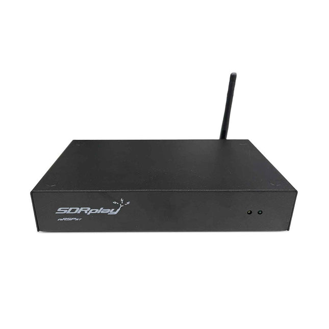
  • SDRplay nRSP - ST Networked Radio Receiver (1 kHz to 2 GHz) - Elektor

    SDRplay SDRplay nRSP-ST Networked Radio Receiver (1 kHz to 2 GHz)

    The nRSP-ST is a networked general coverage radio receiver for frequencies from 1 kHz to 2 GHz with up to 10 MHz of spectrum visibility. The nRSP-ST is your own personal remotely accessible SDR which can also be shared with a small number of trusted friends or colleagues. The nRSP-ST addresses the needs of radio enthusiasts who want a 'plug-and-play' solution for remote reception. As well as achieving this, we have addressed typical internet bandwidth limitations with the creation of a novel IQ Lite mode, which efficiently delivers channels of IQ data. We are also introducing the ability to control and store IQ recordings at the remote location. The nRSP-ST is ideal for anyone wanting a wideband remote receiver without needing computer skills and hours of set-up time and ongoing maintenance at the remote location. Features "Plug and play" integrated, networked general coverage receiver: Combines a receiver, a host computer and a whole lot more – all in one box! Apply power and connect to the internet (Ethernet or Wi-Fi) and the nRSP-ST is automatically accessible from anywhere Multi-platform SDRconnectTM software supports local operation or remote access on Windows, MacOS or Linux platforms The nRSP-ST & SDRconnect are configurable for available network bandwidth: In Full IQ mode, the nRSP-ST provides IQ data transfer of the visible spectrum bandwidth (e.g. for high-speed LAN or superfast internet connectivity) In IQ Lite mode, the nRSP-ST provides IQ data of channels up to 192 kHz wide (e.g. for digital decoding by the client) In Compact mode the nRSP-ST provides compressed audio (ideal for slower internet connections) Supports multiple client connections with a simultaneous mixture of connection modes – an admin tool allows you to assign usernames and timeouts to trusted friends or colleagues. All modes support visualization of up to 10 MHz spectrum bandwidth Two remote connection options: Use a remote SDRconnect client or Use the built-in web-server for remote access from any web browsing capable device, including Android/iOS tablets and phones The nRSP-ST offers the ability to record IQ and audio files to a NAS (network attached storage) device if available on the LAN. The 14-bit ADC full featured wideband SDR receiver covers all frequencies from 1 kHz through VLF, LF, MW, HF, VHF, UHF and L-band to 2 GHz, with no gaps Remotely monitor up to 10 MHz of spectrum at a time from a choice of 3 antennas Flash upgradable for future feature enhancements Included 1x nRSP-ST Receiver 1x WLAN antenna 1x Power supply 1x Manual Downloads Release notes Software

    € 554,18

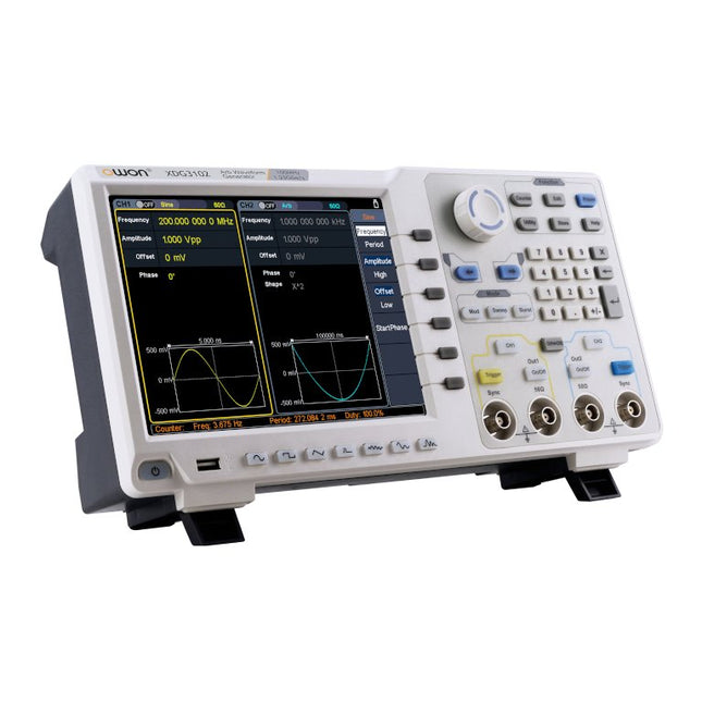
  • OWON XDG3102 2 - ch Arbitrary Waveform Generator (100 MHz) - Elektor

    OWON OWON XDG3102 2-ch Arbitrary Waveform Generator (100 MHz)

    Features Advanced DDS technology, up to 250 MHz frequency output 1.25 GS/s sampling rate, and 1 μHz frequency resolution Up to 1M arbitrary waveform length Vertical resolution: 14 bits Comprehensive waveform output: 6 groups waveforms, and 152 group built-in arbitrary waveforms Comprehensive modulation options: AM, FM, PM, FSK, 3FSK, 4FSK, PSK, OSK, ASK, BPSK, PWM, sweep, and burst High-accuracy frequency counter integrated, ranging from 100MHz till 200MHz SCPI and LabVIEW supported 8-inch 800 x 600 pixels touch screen LCD Specifications XDG3102 Channel 2 Frequency Output 100MHz Sample Rate 1.25GSa/s Vertical Resolution 14 bits Waveform Standard Waveform sine, square, pulse, ramp, noise, and harmonic Arbitrary Waveform exponential rise, exponential fall, sin(x)/x, step wave, and others, total of 150 built-in waveforms, and user-defined arbitrary waveform Frequency (resolution 1μHz) Sine 1μHz - 100MHz Square 1μHz - 40MHz Pulse 1μHz - 25MHz Ramp 1μHz - 5MHz Harmonic 1μHz - 50MHz Noise 120MHz (-3dB, typical) Arbitrary Waveform built-in waveform: 1uHz - 15MHzuser-defined waveform: 1uHz - 50MHz Accuracy ±1ppm, 0°C - 40°C Amplitude Amplitude (50Ω) 1mVpp - 10Vpp (≤40MHz); 1mVpp - 5Vpp (≤80MHz) 1mVpp - 2.5Vpp (≤120MHz); 1mVpp - 1Vpp (≤250MHz) Amplitude(high impedance) 2mVpp - 20Vpp (≤40MHz); 2mVpp - 10Vpp (≤80MHz); 2mVpp - 5Vpp (≤120MHz); 2mVpp - 2Vpp (≤250MHz) Resolution 1mV or 4 digits DC Offset Range (50Ω) ±(5 Vpk - Amplitude Vpp/2) Range (high-Z, open circuit) ±(10 Vpk - Amplitude Vpp/2) Accuracy ±(1% of |setting| + 1mV + Amplitude Vpp x 0.5%) Resolution 1mV or 4 digits Load Impedance 50Ω (typical) Accuracy ±(1% of setting + 1 mVpp) (typical, 1kHz sine, 0V offset) Sine Wave Spectrum Purity Harmonic Distortion Typical (0dB) DC - 1MHz: <-65dBc 1MHz - 10MHz: <-60dBc 10MHz - 120MHz: <-50dBc 120MHz - 200MHz: <-45dBc Total Harmonic Distortion <0.05 %, 10 Hz to 20 kHz, 1 Vpp Spurious (non-harmonic), Typical (0dB) ≤10MHz: <-70dBc >10MHz: <-70dBc + 6dB/ octave Phase Noise Typical (0 dBm, 10 kHz deviation) 10MHz: ≤-110dBc/Hz Square Rise/Fall Time <5ns Overshoot <3% Duty Cycle 50.0% (fixed) Jitter (rms) 300ps + 100ppm Pulse Pulse Width 12ns - 996875s Leading/Trailing Edge Time ≧7ns Overshoot <3% Jitter (rms) 300ps + 100ppm Ramp Linearity ≤1% of peak output (typical, 1kHz, 1 Vpp, 50% symmetry) Symmetry 0% to 100% Harmonic Harmonic Order ≤16 Harmonic Type even, odd, all, user Harmonic Amplitude could be set for all the harmonics Harmonic Phase Arbitrary Waveform Length 2 points - 1M points Vertical Resolution 14 bits Minimum Rise/Fall Time <7ns Jitter (rms) 3ns Modulation Type AM, FM, PM, PWM, FSK, 3FSK, 4FSK, PSK, OSK, ASK, BPSK, sweep, and burst AM Carrier Waveform sine, square, ramp, and arbitrary (except DC) Source internal / external Modulating Waveform sine, square, ramp, noise, and arbitrary Depth 0.0% - 100.0% Modulating Frequency 2 mHz - 100 kHz FM Carrier Waveform sine, square, ramp, and arbitrary (except DC) Source internal / external Modulating Waveform sine, square, ramp, noise, and arbitrary Modulating Frequency 2 mHz - 100 kHz PM Carrier Waveform sine, square, ramp, and arbitrary (except DC) Source internal / external Modulating Waveform sine, square, ramp, noise, and arbitrary Phase Deviation 0° - 180° Modulating Frequency 2 mHz - 100 kHz PWM Carrier Waveform pulse Source internal / external Modulating Waveform sine, square, ramp, noise, and arbitrary Width Deviation 0 ~ minimum (pulse duty ratio, 100% - pulse duty ratio) Modulating Frequency 2 mHz - 100 kHz FSK / 3FSK / 4FSK Carrier Waveform sine, square, ramp, and arbitrary (except DC) Source internal / external Modulating Waveform square with 50% duty cycle Key Frequency 2 mHz - 1MHz PSK Carrier Waveform sine, square, ramp, and arbitrary (except DC) Source internal / external Modulating Waveform square with 50% duty cycle Key Frequency 2 mHz - 1MHz OSK Carrier Waveform sine, square, ramp, and arbitrary (except DC) Source internal Oscillation Time square with 50% duty cycle Key Frequency 2 mHz - 1MHz ASK Carrier Waveform sine, square, ramp, and arbitrary (except DC) Source internal / external Modulating Waveform square with 50% duty cycle Key Frequency 2 mHz - 1MHz BPSK Carrier Waveform sine, square, ramp, and arbitrary (except DC) Source internal Modulating Waveform square with 50% duty cycle Key Frequency 2 mHz - 1MHz Sweep Carrier Waveform sine, square, ramp, and arbitrary (except DC) Type linear, and log Direction up, and down Sweep Time 1 ms to 500s, ± 0.1% Trigger Source internal, external, and manual Burst Carrier Waveform sine, square, ramp, pulse, and arbitrary (except DC) Burst Count 1 to 50,000 period, infinite, gating Internal Period 10 ns - 500 s Gated Source external trigger Frequency Counter Function frequency period, +width, -width, +duty, and -duty Frequency Range 100 MHz - 200 MHz Frequency Resolution 7 digits Input / Output Display 8”800 x 600 pixels touch screen LCD Type frequency counter, external modulation input,external trigger input,external reference clock input / output Communication Interface USB Host, USB Device, and LAN Dimension 340 x 177 x 90 mm Weight 2.50 kg

    € 650,00

  • OWON XDG2035 2 - ch Arbitrary Waveform Generator (35 Mhz) - Elektor

    OWON OWON XDG2035 2-ch Arbitrary Waveform Generator (35 Mhz)

    The 2-channel OWON XDG2035 is a function/waveform generator that can generate signals with a maximum frequency of 35 Hz. The generator has a resolution of 1 µHz and a sample rate of 500 MSa/s. The OWON XDG2035 is capable of generating 6 standard waveforms and 150 arbitrary waveforms. With the included software you can write advanced functions up to 10 million points. Waveforms can be saved to the function generator's internal memory using a PC via USB or LAN. The OWON XDG2035 also supports SCPI commands and LabView. The function generator has an integrated high-quality frequency counter, which can operate from 100 to 200 MHz. Features Max. 35 MHz frequency output 500 MSa/s Sample rate, Vertical resolution 1μHz 14 bits Vertical Resolution, 10 Marb waveform length Comprehensive waveform output: 6 basic waveforms,and 150 built-in arbitrary waveforms Comprehensive modulation functions: AM, FM, PM, FSK, 3FSK, 4FSK, PSK, OSK, ASK, BPSK, PWM, Sweep, and Burst High-accuracy frequency counter integrated, supported range 100-200 MHz SCPI and LabVIEW supported 7 inch multi-touch screen (800 x 480 pixels) Specifications Channel 2 Frequency Output 35 MHz Sample Rate 500 MSa/s Vertical Resolution 14 bits Waveform Standard Waveform sine, square, pulse, ramp, noise, and harmonic Arbitrary Waveform exponential rise, exponential fall, sin(x)/x, step wave, and others, total 150 built-in waveforms, and user-defined arbitrary waveform Frequency (resolution 1 μHz) Sine 1 μHz-100 MHz Square 1 μHz ~ 30 MHz Pulse 1 μHz ~ 25 MHz Ramp 1 μHz ~ 3 MHz Noise (-3 dB, typical) 100 MHz Arbitrary Waveform 1 μHz ~ 15 MHz Harmonic 1 μHz ~ 50 MHz Accuracy ±2ppm, 25°C ±5°C Waveform Length 2 points - 10M points Amplitude Into 50Ω load 1mVpp ~ 10Vpp (≤25 MHz); 1mVpp ~ 5Vpp (≤60 MHz); 1mVpp ~ 2.5Vpp (≤100 MHz) Modulation Type AM, DSB-AM, FM, PM, ASK, FSK, PSK, BPSK, QPSK, 3FSK, 4FSK, OSK, PWM, SUM Frequency Counter Function Frequency, period, +width, -width, +duty, and -duty Frequency Range 100 ~ 200 MHz Frequency Resolution 7 digits Input/Output Input mode frequency counter, external modulation input, external trigger input, internal clock output, external reference clock input/output Communication Interface USB Host, USB Device, LAN, RS232 (optional) Mechanical specifications Dimensions 340 x 177 x 90 mm Weight 2.3 kg Included 1x OWON XDG2035 1x Power Cord 1x CD-ROM 1x Quick start guide 1x USB Cable 1x BNC-BNC Cable Downloads Quick Guide

    € 339,00

  • OWON HDS120 (2 - in - 1) True RMS Multimeter & Oscilloscope - Elektor

    OWON OWON HDS120 (2-in-1) True RMS Multimeter & Oscilloscope

    The OWON HDS120 is a precise 4½-digit True RMS multimeter (20,000 counts), ideal for professionals, makers, and students. It offers intelligent probe detection, automatic waveform measurements (Vmax, Vmin, Vp-p, Vavg, Vrms, and frequency) and a fully featured handheld oscilloscope (1 MHz). Features Multifunctional Measuring Instrument: 4½-digit Multimeter + Oscilloscope Automatic Waveform Measurements: Including Vmax, Vmin, Vp-p, Vavg, Vrms, and frequency. User-Friendly Design: Clearly labeled keys for easy operation and increased device lifespan. Intelligent Probe Detection: Automatically switches measurement functions based on the probe insertion, effectively preventing instrument damage caused by incorrect operation. Efficient Energy Management: Powered by 18650 lithium batteries, ensuring longer operating time and enhanced reliability for extended measurement tasks. Safe High-Voltage Measurement: Complies with CAT Ⅲ 1000 V standards, allowing safe and direct measurement of high-voltage waveforms up to 1000 V, broadening application possibilities. High-Definition Display: Features a 2.8-inch IPS screen with a wide viewing angle, ensuring clear readability from any perspective. Adaptive Environmental Display: High-brightness and high-contrast dual-theme display modes provide optimal visibility under bright and low-light conditions, improving overall usability. Multimeter Specifications Measurement Range Accuracy DC Voltage (V) 20.000mV / 200.00mV / 2.0000V / 20.000V / 200.00V / 1000.0V ±(0.1%+5dig) AC Voltage (V) 20.000mV / 200.00mV / 6.0000V / 60.000V / 600.00V / 750.00V ±(0.6%+10dig) DC Current (A) 200.00uA / 2000.0uA / 20.000mA / 200.00mA / 2.0000A / 10.000A ±(0.5%+10dig) AC Current (A) 200.00uA / 2000.0uA / 20.000mA / 200.00mA / 2.0000A / 10.000A ±(0.8%+10dig) Resistance (Ω) 200.00Ω / 2.0000kΩ / 20.000kΩ / 200.00KΩ / 2.0000MΩ / 20.000MΩ / 100.00MΩ ±(0.3%+5dig) Capacitance (F) 2.000nF / 20.00nF / 200.0nF / 2.000μF / 20.00μF / 200.0μF / 2.000mF / 20.00mF ±(3.0%+10dig) Frequency (Hz) 200.00Hz / 2.0000kHz / 20.000kHz / 200.00kHz / 2.0000MHz / 20.000MHz ±(0.1%+5dig) Duty Cycle 0.1%~99.9% (typical value: Vrms=1V, f=100Hz) ±(1.2%+3dig) 0.1%~99.9% (≥1kHz) ±(2.5%+10dig) Diode 3.0000V ±(1.0%+10dig) On-Off 1000.0Ω Display 20000 Oscilloscope Specifications Analog bandwidth 1 MHz (only ACV scale) Channel 1 Time base range 2.5us~10s/grid Voltage vertical sensitivity range 30 mV~500 V/grid Vertical amplitude accuracy ±(5% + 0.2div) Maximum voltage limit 1000 V DC+AC Peak value Trigger mode Auto/Normal/Single Auto set Time base/Vertical amplitude/Trigger value Maximum sample 5.0 MSa/s Input impedance ≈10 MΩ Time base accuracy ±(0.01% + 0.1div) Current vertical sensitivity range 100 μA~5 A/grid Measurement function Vmax, Vmin, Vp-p, Vavg, Vrms, Hz Maximum current limit 15 A DC+AC Peak value Trigger edge Rise edge/Fall edge General Specifications Display 2.8" LCD (320 x 240) Low battery indication Yes Backlight Yes Sleep Mode Yes Input Protection Yes Relative Measurement Yes Input Impedance ≥10 MΩ Battery 18650 Lithium Safety Compliance CAT III 1000V Dimensions 93 x 41.5 x 188 mm Weight 0.35 kg Included 1x OWON HDS120 Multimeter & Oscilloscope 2x Multimeter leads 1x USB cable 1x Storage bag 1x Manual Downloads Datasheet Manual

    € 59,00

  • Micsig CP2100A AC/DC Current Probe

    Micsig Micsig CP2100A AC/DC Current Probe

    Features Bandwidth: DC-800 KHz Maximum measurable current: 100 Apk (70.7 Arms) Max. conductor diameter: 13 mm Auto & Manual "Zero" function Directly powered by USB port Standard BNC interface, compatible with any oscilloscope Specifications Bandwidth DC-800 KHz Rise time <= 583 ns Ranges 10 A / 100 A Output sensitivity 0.1 V/A (10 A) 0.01 V/A (100 A) DC accuracy 3% ±50 mA (10 A) 4% ±50 mA (100 A, 500 mA - 40 Apk) 15% (100 A, 40 Apk -100 Apk) Signal delay < 150 ns (10 A) < 200ns (100 A) Current measurement range 50 mA - 10 Apk (10 A) 1 A - 100 Apk (100 A) Max. Voltage CAT III 300 V CAT II 600 V Power supply DC 5 V Downloads Quick Guide Datasheet Manual

    € 309,76

  • Seeed Studio RF Explorer WSUB1G+ Slim - Elektor

    Seeed Studio Seeed Studio RF Explorer WSUB1G+ Slim Spectrum Analyzer

    Features Internal LNA amplifier and selectable attenuator Low frequency support from 50KHz covering LF, MF, HF, VHF and UHF up to 960Mhz New HELP and SET buttons to improve user interface and configuration selection with 2-clicks Wide band coverage to all popular sub-1Ghz bands, including FM, TV and DTV, ISM, RFID, GSM, etc. Ideal choice for HAM bands from 160meters to 33cm Pocket size and light weight Solid metal case Spectrum Analyzer mode with Peak Max and Hold, Normal, Overwrite and Averaging modes High capacity internal Lithium battery for 20hs+ of continuous run, rechargeable by USB Multi-platform Windows/Linux/MacOS Open Source software and API libraries Can be extended with internal Expansion Modules for additional band and functionality Specifications Frequency band: 0.05 MHz - 960 MHz Frequency span: 0.1 MHz - 960 MHz Internal selectable LNA 25 dB gain Internal selectable Attenuator 30 dB Graphics LCD 128 x 64 pixels, great visibility outdoors Support included for Windows, Linux and MacOS X Backlight for great visibility indoor Internal Lithium Ion 1800mA/h rechargeable battery Standard SMA 50 Ω connector Wideband 144/433MHz dual band telescopic antenna included UHF 400-900 MHz rubber duck articulated antenna included Amplitude resolution: 0.5dBm Dynamic range: -125 dBm to 10 dBm Absolute Max input power: +30dBm Average noise level (typical LNA): -125 dBm Frequency stability and accuracy (typical): +-10 ppm Amplitude stability and accuracy (typical): +-2d Bm Frequency resolution: 1kHz Resolution bandwidth (RBW): automatic 2.6 kHz to 600 kHz Included 1x RF Explorer WSUB1G+ Spectrum Analyzer 1x Mini USB cable 1x Dual band 144/430MHz Telescopic antenna 1x UHF 400-900Mhz antenna 1x EVA case

    € 204,49

  • UNI - T UT8803E Multimeter - Elektor

    Uni-Trend UNI-T UT8803E True RMS Multimeter

    The UT8803E is a portable, AC-powered 3⅚ digital multimeter with 6000 counts with automatic measuring range and large display with backlight. The UT8803E can be used to measure AC/DC voltage, AC/DC current, resistance, frequency, capacitance, inductance, triode (HFE), diode (LED), thyristor (SCR), and on-off switching. Features Extreme value and reference value operation, with analog bargraph Multiple measurement parameters optional D/Q parameters of capacitance and inductance can be measured Measurement resolution 3.5-inch, maximum measurement value 5999 Specifications Measurement Resolution 3⅚, Maximum Measurement Value 5999 Measurement Rate 2-3 measurements/s DC Voltage Range 600 mV~1000 V DC Current Range 600 µA~20 A AC Voltage Range 600 mV~750 V (True RMS) AC Current Range 600 µA~20 A (True-RMS) Resistance Range 600 Ω~60 MΩ Capacitance Range 6 nF~60 mF Inductance Range 600 µH~100 H Frequency Measurement Range 600 Hz~20 MHz Duty Cycle Measurement Range 5%~95% Mathematical Operation Maximum, minimum, relative value, trend chart Interface USB device (can be connected to the upper computer control software) Frequency response 100 KHz Downloads Datasheet User Manual Programming Manual Software

    € 192,39

  • Seeed Studio RF Explorer 3G Combo - Handheld Spectrum Analyzer - Elektor

    Seeed Studio Seeed Studio RF Explorer 3G Combo Spectrum Analyzer

    You can use RF Explorer 3G Combo equally well outdoor and indoor, and you can also connect it to a PC for extra functionality using standard mini-USB 2.0 connector. This model includes a WSUB1G baseline unit plus an RFEMWSUB3G Expansion Module conveniently assembled and tested. It comes with two SMA connectors and two antennas,a dual band telescopic 144 / 430 MHz antenna for all Sub-GHz frequencies and a whip helical antenna for 2.4 GHz band. Additional, specific band antennas may be needed to cover efficiently some of the frequencies supported. The combination of these two models offer the wide band coverage of the WSUB3G module, together with the highest sensitivity and quick response of the WSUB1G model for the popular sub-1GHz frequencies. Features Pocket size and light weight Solid aluminum metal case Includes a transport EVA carry case for RF Explorer Spectrum Analyzer mode with Peak Max and Hold, Normal, Overwrite and Averaging modes Lifetime free firmware upgrades available, open to community requested features High capacity Lipo for 16 hours+ of continuous run, rechargeable by USB Windows PC client Open Source Can be extended with internal Expansion Modules for additional band and functionality Wide band coverage to all popular RF frequencies, starting at 15 MHz and going up to 2.7 GHz. This includes very interesting frequency areas such as 2 m HAM radio, all VHF and UHF, FM radio, GPS, WiFi and WiMax, Bluetooth, etc. Firmware: RF Explorer 3G Combo is delivered with upgraded firmware v1.09. Note some of the features and operation accuracy will be improved in upcoming free firmware revisions. Specifications Battery Lithium Cells / Batteries contained in equipment UN3481 - PI967 Frequency band 15-2700 MHz Frequency span 112 KHz - 600 MHz Graphics LCD 128 x 64 pixels, great visibility outdoors PC Windows client supports Windows XP/Vista/Win7 both 32 and 64bits Backlight for great indoor visibility 2 standard SMA 50 ohms connector, one for Sub-GHz wideband Nagoya NA-773 telescopic antenna included and another 2.4 GHz one for 15-2700 MHz band with helical antenna included. Amplitude resolution 0.5 dBm Dynamic range Left SMA port (WSUB1G) -115 dBm to 0 dBm Right SMA port (WSUB3G) -110 dBm to -10 dBm Absolute Max input power Left SMA port (WSUB1G) +5 dBm Right SMA port (WSUB3G) +30 dBm Average noise level (typical) -110 dBm Frequency stability and accuracy (typical) +-10 ppm Amplitude stability and accuracy (typical) +-6 dBm Frequency resolution 1 KHz Resolution bandwidth (RBW) automatic 3 KHz to 600 KHz Weight 185 g Size 113 x 70 x 25 mm Included RF Explorer 3G Combo Nagoya NA-773 wideband telescopic antenna 2.4 GHz band antenna EVA Case Documentation For more info and to get started with your RF Explorer, visit the start page. For questions and support, please visit https://support.rf-explorer.com

    € 279,95

  • Last Stock! Red Pitaya STEMlab 125-14 PRO Gen 2 Starter Kit (Bundle)

    Red Pitaya Red Pitaya STEMlab 125-14 PRO Gen 2 Starter Kit (incl. Book)

    2 in stock

    This bundle includes the Red Pitaya STEMlab 125-14 PRO Gen 2 Starter Kit and the new book "Experimenting with Red Pitaya STEMlab Gen 2". The Red Pitaya STEMlab 125-14 PRO Gen 2 Starter Kit is a powerful and flexible platform for signal processing, data acquisition, and electronic measurement applications. Designed for engineers, developers, researchers, and educators, this kit provides everything required to start building advanced measurement and control systems. At the core of the kit is the STEMlab 125-14 PRO Gen 2 board, an upgraded and ultra-lightweight development platform. Powered by the Xilinx Zynq-7010 SoC with 512 MB of RAM, it combines FPGA programmability with ARM processing power to enable high-performance instrumentation and custom signal-processing solutions. The board offers 14-bit ADC and DAC resolution, a 125 MS/s sampling rate, an input range of ±20 V, and up to 60 MHz bandwidth. Its improved low-noise analog front-end, USB-C connectivity, and compact design make it suitable for demanding applications such as RF development, radar systems, photonics research, software-defined radio (SDR), and industrial automation. The Starter Kit includes all essential accessories for immediate use: a microSD card with preinstalled operating system, power supply, Ethernet cable for remote access, two 100 MHz oscilloscope probes, and SMA-to-BNC adapters for flexible signal connections. The Red Pitaya STEMlab 125-14 PRO Gen 2 Starter Kit is an excellent platform for rapid prototyping, FPGA development, measurement instrumentation, and advanced electronics experimentation. Features 14-bit ADC and DAC resolution 125 MS/s sampling rate ±20 V input range Up to 60 MHz bandwidth Xilinx Zynq-7010 SoC (FPGA + ARM processor) 512 MB RAM Low-noise analog front- and back-ends Applications RF development and testing Radar and wireless systems Software-defined radio (SDR) Photonics and optical research Industrial automation and control systems Signal analysis and instrumentation Rapid prototyping of electronic measurement systems Specifications Processor Dual-core ARM Cortex-A9 FPGA AMD Xilinx Zynq-7010 SoC RAM 512 MB (4 Gb) Storage microSD card (up to 32 GB) Operating System Linux-based Red Pitaya OS ADC Resolution 14-bit DAC Resolution 14-bit Bandwidth 60 MHz (DC) Sampling Rate 125 MS/s Analog Input Channels 2 Analog Output Channels 2 Input Voltage Range ±1 V (LV) / ±20 V (HV) Input Impedance 1 MΩ / 10 pF Output Voltage Range ±1 V Ethernet 1x Gigabit Ethernet (RJ45) USB 2x USB-C 2.0 (for power and console) Digital I/O 16x GPIO (3.3 V) Communication Interfaces I²C, SPI, UART, CAN Power Supply 5 V/3 A via USB-C Dimensions 106.8 x 60.0 x 17.9 mm Included 1x Red Pitaya STEMlab 125-14 PRO Gen 2 board 2x 100 MHz oscilloscope probes 2x SMA-to-BNC adapters 1x microSD card with preinstalled OS 1x USB-C Power supply 1x Ethernet cable Downloads Documentation Schematics Book: Experimenting with Red Pitaya STEMlab Gen 2 With this new book, Red Pitaya goes beyond a versatile board. It becomes a powerful laboratory instrument for precision measurement, analysis, and control. From the fundamentals of electronic project development, monitoring, control, and design to testing, this book walks you step-by-step through everything you need to know to harness the full potential of Red Pitaya hardware and software. The book presents real-time, FPGA-based projects that are developed on a PC using the Vivado environment, then transferred to the Red Pitaya for execution and testing. You will learn about enhanced performance, expanded I/O capabilities, improved FPGA features, and advanced connectivity options that open up new frontiers for precision measurement, monitoring, and control in your embedded applications. Inside the book you will discover: A deep dive into Red Pitaya architecture and hardware design Electronic experiments using Red Pitaya for measurement and monitoring Hands-on projects using the Python programming language Practical guidance for FPGA programming using Red Pitaya Red Pitaya FPGA projects using the Verilog HDL under Vivado IDE Practical design of electronic projects including measurement and testing Step-by-step examples that bridge theory and real-world implementation Whether you are designing your own electronic circuits, developing signal analysis tools, or creating real-time control or monitoring systems, this book provides you the knowledge and confidence you need to fully learn and customize the Red Pitaya platform.

    2 in stock

    € 799,00

    Best Price

  •  -17% Elektor Low-Noise Lab Power Supply

    Elektor Labs Elektor Low-Noise Lab Power Supply

    The Elektor Low-Noise Lab Power Supply is a fully analogue, adjustable, medium-power symmetrical bench supply that contains no switching or digital components. It provides an output voltage adjustable between 0 V and ±22 V, and an output current adjustable from 0 A to 1 A. Because it avoids any form of switching circuitry, the design delivers extremely low noise. To display both output voltages and currents, four miniature moving-coil panel meters are used. Most modern laboratory power supplies and AC adapters employ switch-mode techniques. Even the best examples inevitably exhibit high-frequency ripple and other switching artefacts on their output, which can interfere with the testing of sensitive analogue circuits and disturb low-level measurements. To overcome this, the concept here is a completely analogue power supply. Although less efficient than its switch-mode counterparts, the reduced efficiency is of little importance for test-bench use and ensures cleaner, more reliable measurement results. Because many analogue circuits require a symmetrical supply, this design delivers positive and negative output voltages of equal magnitude. A small amount of adjustment is available to compensate for any imbalance. Naturally, a variable current-limit function is also included. Specifications Output Voltage 0…+22 V, 0, −22 V Output Current 0…+1 A, 0…−1 A Noise −85 dBV, (at 0.95 A/20 V, B = 22 kHz) −84 dBV (at 0.95 A/20 V, B > 500 kHz) Ripple 50 µVRMS (at 950 mA/20 V, B = 22 kHz, mainly 100 Hz component) Included 3x PCBs: Regulator (PCB-1), Mains Filter (PCB-2) and Transformer (PCB-3) All the components except the AC transformers 4x moving-coil meters Additional parts for wiring (wires, banana sockets, IEC Power entry module, etc.) Not included The three AC transformers An enclosure Parts List For the Regulator PCB (240386-1) Resistors (250 mW, 1%) R1 = 12 Ω R2, R8, R37, R62 = 1 MΩ R3, R7, R10, R13, R17, R20, R22, R30, R35, R42, R45, R47, R55, R60 = 100 Ω, 600 mW R4, R5 = 4.7 kΩ R6 = 100 kΩ R9, R12, R14, R36, R38, R39, R61, R63, R66, R72, R78, R79 = 10.0 kΩ, 600 mW R11 = 9.76 kΩ, 600 mW R15, R40 = 44.2 kΩ, 600 mW R16, R41, R77 = 1 kΩ R18, R43 = 1.5 kΩ, 1 W, 5% R19, R44 = 470 Ω, 1 W, 5% R21, R46 = 330 Ω, 600 mW R23, R24, R48, R49 = 1.0 Ω, 1 W R25, R50 = 1 kΩ, 1 W, 5% R26, R28, R51, R53 = 1.000 kΩ 0.1%, 15 ppm/C R27, R29, R52, R54 = 10.00 kΩ 0.1%, 15 ppm/C R31, R56 = 1.2 kΩ, 1 W, 5% R32, R57 = 47 kΩ R33, R58 = 270 Ω R34, R59 = 27 kΩ R64, R69 = 12.0 kΩ R65 = 3.0 kΩ, 600 mW R67, R80 = 470 Ω, 600 mW R68, R70 = 6.8 kΩ, 600 mW R71 = 30.0 kΩ,, 600 mW R73, R74, R75, R76 = 10 MΩ P1, P2, P3 = 10 kΩ, 200 mW, 20%, potentiometer, 1 turns, single, lin., panel mount P4, P5 = 500 Ω, 500 mW, 10%, trimmer, 25 turns, 3296Y-1-501LF Bourns P6, P7 = 10 kΩ, 500 mW, 10%, trimmer, 25 turns, 3296Y-1-501LF Bourns Capacitors C1 = 100 nF, 50 V, 10%, ceramic X7R, LS 5 mm C2, C3, C6, C7, C30 = 10 µF, 63V, 20%, LS 2.5 mm, 3000hours@105°C C4, C5, C8, C9, C13, C14, C18, C19, C23, C24, C28, C29, C31, C32, C38, C39 = 100 nF, 250 V, 10%, PET, LS 7.5 mm C10, C20 = 47 nF, 100 V, 5%, PET, LS 5 mm C11, C21 = 10 nF, 100 V, 5%, PET, LS 5 mm C12, C22 = 220 µF, 35 V, 20%, 0.024 Ω, LS2.5/3.5 mm, Ir 3.4 A, 2000hours@125°C, polymer C15, C25 = 120 µF, 50 V, 20%, ESR 0.02 Ω, Diam. 10 mm max., LS 5 mm C16, C26 = 15 nF, 100 V, 5%, PET, LS 5 mm C17, C27 = 47 nF, 100 V, 5%, PET, LS 5 mm C33, C34 = 22 µF, 50 V, 20%, LS 2 mm, 10000 hours @ 105°C C35, C36, C44, C45 = 1 µF, 100 V, 10%, LS 5 mm, ceramic X7R C37 = 100 uF, 50 V, 20%. LS 3.5 mm C40, C41, C42, C43, C46, C47, C48, C49 = 1000 µF, 50 V, 20%, LS 5/7.5 mm, Ir 3.32 A, 10000hours@105°C, D 16 mm C50, C51, C52, C53 = 47 nF, 100 V, 10%, ceramic X7R, LS 5 mm Inductors L1, L2 = 4.7 µH, 3.2 A, 0.033 Ω, LS 5 mm, RLB0914-4R7ML Bourns L3 = Commom mode choke, 14.5 mH, 3 A, SSRH24NH-30145 Kemet Semiconductors D1, D2, D3, D4, D5, D9, D10, D11, D15 = BAT85, DO-34 D6, D7, D12, D13 = SR560, DO-201AD D8, D14, D16 = 1N4148, DO-35 D17 = Zenerdiode, 5.6 V, 0.5 W, DO-41 D18, D19 = 1N4004, DO-41 D20, D21 D22, D23 = V30100CI-M3/P, dual common cathode, TO-220 D24 = Zener diode, 30 V, 1 W, DO-41 LED1, LED2 = LED, red, T-1 (3 mm) LED3, LED4 = LED, green, T-1 (3 mm) TVS1, TVS2 = BZW50-33B, R6 T1, T2, T4 = BC337.25, TO-92 T3 = NJW0302G, TO-3P T5, T6, T8 = BC327.25, TO-92 T7 = NJW0281G, TO-3P T9 = BD139, TO-126 (SOT-32) IC1 = LM334Z, TO-92 IC2 = LM4040AIZ-5.0/NOPB, TO-92 (TO-226AA-3) IC3, IC4 = OPA2992IDR, SOIC-8 IC5, IC6 = OPA4992IDR, SOIC-14 IC7 = OPA992IDBVR, SOT-23-5 IC8 = LM339N, DIP-14 IC9 = LM317, TO-220 IC10 = LM337, TO-220 Others F1, F2 = 5×20 mm fuse, 1.6 A, fast acting HS1, HS2 = Heatsink MC33271 (for T3/T7), 2.7°C/W, PCB mount, height 63.5 mm K1, K4 = 3-way screw terminal block, LS 3.5 mm, max. 1.5 mm² K2, K3 = 3-way screw terminal block, LS 3.5 mm, max. 1 mm² M1, M3 = Moving coil meter, Range 30 V, type 91C4, 45×45 mm M2, M4 = Moving coil meter, Range 1 A, type 91C4, 45×45 mm² RE1 = Relay DPDT,5V, UA2-5NU Miscellaneous 3× 3-way screw terminal block, LS 3.5 mm, max. 1 mm² (for P1, P2, P3) 4× Pin header, 1×2, vertical, pitch 2.54 mm (for LED1, LED2, LED3, LED4) 4× Pin socket, 1×2, vertical. pitch 2.54 mm (for LED1, LED2, LED3, LED4) 2× Heatsink FK222SA220, 20°C/W, PCB mount (for IC9 & IC10) 2× Mica thermal pad for TO-220, 12×18×0.05 mm (for IC9 & IC10) 2× Insulating bushing IB 6, TO-220 (for IC9 & IC10) 2× Ceramic thermal pad, 23×20×2 mm (for T3 & T7) 2× PCB Fuse Holder, for 5×20 mm fuse, 10 A (for F1, F2) 2× Cover for PCB Fuse Holder, transparent (for F1, F2) 2× 2-way screw terminal block, LS 3.5 mm, max. 1 mm² (for M1 & M3) 2× 2-way screw terminal block, LS 3.5 mm, max. 1.5 mm² (for M2 & M4) 8× M3 solder lug, thickness 0.35 mm (for M1…M4) M4 solder lug, thickness 0.35 mm (to connect 4 mm banana connectors) Screened cable, 1 pair, 2×24 AWG/0.22 mm², 1 m (for P1, P2 & P3) IC socket, DIP, 14 contacts (for IC8) M3 washer, plain, steel M3 screw, 16 mm, steel, pan head M3 nut M3 spring washer 50 mm M3 standoff, steel, male-female 12 mm M3 standoff, steel, male-female 10 mm M3 standoff, steel, male-female M3 screw, 8 mm, steel, pan head For the Mains Fiter PCB (240386-2) Resistor R1 = 220 kΩ, 1 W, 500 V, 5% Capacitors C1, C2 = 470 nF, 305 VAC, Class X2, 11 × 27 mm max., LS 15/22.5 mm C3, C4, C5, C6 = 2.2 nF, 300 VAC, Class Y2, 13 × 4 mm, LS 10 mm, PP Inductors L1, L2 = Common-mode choke, 6.8 mH, 1.7 A, TDK B82732R2172B030 Semiconductor MOV1 = TVS varistor, 300 VAC, S14K300 (230 VAC, B72214S0301K101) and SK14K150 (150 VAC, B72214S0151K101) Others K1, K2 = 3-way screw terminal block, LS 7.62 mm F1 = Time-delay fuse, 0.5 A (230 VAC) or 1 A (115 VAC) Miscellaneous 1× Fuse holder, 5×20 mm, 10 A, 500 VAC 1× Transparent fuse cover 4× 10 mm M3 standoff, steel, male–female 4× M3 screw, 8 mm, steel, pan head 4× M3 nut For the Transformer PCB (240386-3) Resistors R1, R2 = 2.7 kΩ, 600 mW, 1% R3 = 10.0 kΩ, 600 mW, 1% Capacitor C1 = 220 µF, 50 V, 20%, Ø10 mm, LS 5 mm, 4000 h @ 105°C Transformers (not included in this kit!) TR1, TR2, TR3 = 2×7 V, 25 VA, PCB-mounted toroid, 70060K Talema Semiconductors D1–D4 = 1N4148, DO-35 D5, D6 = 1N4004, DO-41 D7 = Zener 5.6 V, 1.3 W, DO-41 LED1 = LED, red, T-1 (3 mm) IC1, IC2 = MOC8021M, CTR ≥ 1000%, DIP-6 Others F1, F2, F3 = 160 mA time-delay fuse (230 VAC) or 315 mA time-delay fuse (115 VAC) K1 = 2-way screw terminal block, LS 7.62 mm K2 = 3-way screw terminal block, LS 3.5 mm, max 1.5 mm² K3, K4 = 3-way screw terminal block, LS 3.5 mm, max 1 mm² RE1, RE2 = Relay DPDT, 5 A/250 VAC / 24 VDC Miscellaneaous 1× Pin header 1×2, pitch 2.54 mm + matching socket for LED1 3× Fuse holder 5 × 20 mm, 10 A, 500 VAC + transparent cover 3× M4 screw, 8 mm, pan head + washer for TR1-TR3 8× M3 screw, 8 mm, pan head + nut + washer 8× 10 mm M3 standoff, steel, male–female 2× IC socket, DIP-6 for IC1 & IC2 Additional Parts 1 m red insulated wire, stranded, 1.5 mm² 0.5 m blue insulated wire, stranded, 1.5 mm² 0.5 m black insulated wire, stranded, 1.5 mm², 0.5 m 2 m red insulated wire, stranded, D 0.56 mm (0.25 mm²) 2 m black insulated wire, stranded, D 0.56 mm (0.25 mm²) 0.5 m Multicore Cable, Flexible, 3 Core, 0.75 mm² (24 x 0.2 mm) Red banana socket Black banana socket Blue banana socket Green banana socket IEC Power Entry Module with switch, IEC C14 3 crimp terminals, FASTON, 4.75 x 0.81 mm 3 knobs Links Elektor Labs JumpStarter Page Article (Part 1) Article (Part 2)

    € 299,00€ 249,00

    Best Price

  • Siglent SDS1204X - E 4 - ch Oscilloscope (200 MHz) - Elektor

    Siglent Siglent SDS1204X-E 4-ch Oscilloscope (200 MHz)

    The Siglent SDS1204X-E is a powerful 200 MHz four-channel oscilloscope that is built on the same platform as the very popular SDS1202X-E but with several significant improvements, including two 1 GSa/s ADCs and two 14 Mpt memory modules. Waveform capture rates are up to 100,000 wfms/s in normal mode and 400,000 wfms/s in sequence mode. The SDS1000X-E scopes feature a large 7” 256-level color display with intensity grading and color temperature features. Specifications Bandwidth 200 MHz Sampling Rate (Max.) 1 GSa/s Channels 2CH+EXT4CH Memory Depth (Max.) 7 Mpts/CH (not interleave mode); 14 Mpts/CH (interleave mode) Waveform Capture Rate (Max.) 100,000 wfms/s (normal mode), 400,000 wfms/s (sequence mode) Trigger Types Edge, Slope, Pulse width, Window, Runt, Interval, Dropout, Pattern, Video Serial Trigger (Standard) I²C, SPI, UART/RS232, CAN, LIN Decode Type (Standard) I²C, SPI, UART/RS232, CAN, LIN 16 Digital Channels (four channel series only, option) Maximum waveform capture rate up to 1 GSa/s, Record length up to 14 Mpts/CH USB AWG module (four channel series only, option) One channel, 25 MHz, sample rate of 125 MHz, wave length of 16 kpts Bode plot ( four channel series only) Minimum start frequency of 10 Hz, minimum scan bandwith of 500 Hz, maximum scan bandwidth of 120 MHz (dependent on Oscilloscope and AWG bandwidth), 500 maximum scan frequency points USB WIFI adapter (four channel series only, option) 802.11b/g/b, WPA-PSK, the adapter must be supplied by Siglent to ensure proper functioning Downloads Datasheet Manual Programming Guide

    € 781,44

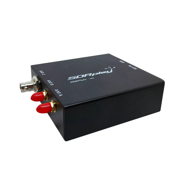
  • SDRplay RSPdx - R2 Single - Tuner 14 - bit SDR Receiver (1 kHz to 2 GHz) - Elektor

    SDRplay SDRplay RSPdx-R2 Single-Tuner 14-bit SDR Receiver (1 kHz to 2 GHz)

    The SDRplay RSPdx-R2 is a wideband full featured single-tuner 14-bit SDR receiver which covers the entire RF spectrum from 1 kHz to 2 GHz giving up to 10 MHz of spectrum visibility. It contains three antenna ports, two of which use SMA connectors and operate across the full 1 kHz to 2 GHz range and the third uses a BNC connector which operates up to 200 MHz. The RSPdx-R2 is an enhanced version of the RSPdx with further design improvements for use at frequencies below 2 MHz. Housed in a strong steel case, in addition to the functionality of the RSP1B, the RSPdx-R2 provides three software selectable antenna inputs and an external clock input. It offers excellent performance through HF and VHF frequencies all the way up to 2 GHz. The RSPdx-R2 also supports an "HDR mode" optimised for the demanding radio reception conditions below 2 MHz. The RSPdx-R2, when used in conjunction with SDRplay’s own software, introduces a special HDR (High Dynamic Range) mode for reception within selected bands below 2 MHz. HDR mode delivers improved intermodulation performance and fewer spurious responses for those challenging bands. Features Covers all frequencies from 1 kHz through VLF, LF, MW, HF, VHF, UHF and L-band to 2 GHz, with no gaps Receive, monitor and record up to 10 MHz of spectrum at a time Significantly improved noise performance below 1 MHz (i.e. for some MF, LF and below) Improved dynamic range below 2 MHz both in tuner mode and HDR mode HDR mode below 2 MHz giving overall dynamic range and selectivity advantages Software selectable choice of 3 antenna ports External clock input for synchronisation purposes, or connection to GPS reference clock for extra frequency accuracy Excellent dynamic range for challenging reception conditions Free use of Windows-based SDRuno software (check website for versions supported) Free use of SDRconnect SDR and server software for Windows, MacOS and Linux (Check website for versions supported) Multiplatform driver and API support including Windows, Linux, Mac and Raspberry Pi 4/5 Strong and growing software support network Calibrated S meter/RF power and SNR measurement with SDRuno (including datalogging to .CSV file capability) Documented API provided to allow demodulator or application development on multiple platforms Applications (Amateur) Shortwave radio listening Broadcast DXing (AM/FM/TV) Panadaptor Aircraft (ADS-B and ATC) Slow Scan TV Multi-amateur band monitoring WSPR & digital modes Weather fax (HF and satellite) Satellite monitoring Geostationary environmental satellites Trunked radio Utility and emergency service monitoring Fast and effective antenna comparison Applications (Industrial) Spectrum Analyser Surveillance Wireless microphone monitoring RF surveying IoT receiver chain Signal logging RFI/EMC detection Broadcast integrity monitoring Spectrum monitoring Power measurement Applications (Educational/Scientific) Teaching Receiver design Radio astronomy Passive radar Ionosonde Spectrum analyser Receiver for IoT sensor projects Antenna research Specifications Frequency Range 1 kHz – 2 GHz Antenna Connector SMA Antenna Impedance 50 Ohms Current Consumption (Typical) 190 mA @ >60 MHz (excl. Bias-T)120 mA @ <60 MHz (excl. Bias-T) USB Connector USB-B Maximum Input Power +0 dBm Continuous+10 dBm Short Duration ADC Sample Rates 2-10.66 MSPS ADC Number of Bits 14 bit 2-6.048 MSPS12 bit 6.048-8.064 MSPS10 bit 8.064-9.216 MSPS8 bit >9.216 MSPS Bias-T 4.7 V100 mA guaranteed Reference 0.5ppm 24 MHz TCXOFrequency error trimmable to 0.01ppm in field Operating Temperature −10˚C to +60˚C Dimensions 113 x 94 x 35 mm Weight 315 g Downloads Datasheet Software RSPdx-R2 vs RSPduo RSPdx-R2 RSPduo Continuous coverage from 1 kHz to 2 GHz ✓ ✓ Up to 10 MHz visible bandwidth ✓ ✓ 14-bit ADC silicon technology plus multiple high-performance input filters ✓ ✓ Software selectable AM/FM & DAB broadcast band notch filters ✓ ✓ 4.7 V Bias-T for powering external remote antenna amplifier ✓ ✓ Powers over the USB cable with a simple type B socket ✓ ✓ 50Ω SMA antenna input(s) for 1 kHz to 2 GHz operation (software selectable) 2 2 Additional software selectable Hi-Z input for up to 30 Mhz operation ✓ Additional software selectable 50Ω BNC input for up to 200 MHz operation ✓ Additional LF/VLF filter for below 500 kHz ✓ 24 MHz reference clock input (+ output on RSPduo) ✓ ✓ Dual tuners enabling reception on 2 totally independent 2 MHz ranges ✓ Dual tuners enabling diversity reception using SDRuno ✓ Rugged black painted steel case ✓ ✓ Overall performance below 2 MHz for MW and LF ++ + Multiple simultaneous applications + ++ Performance in challenging fading conditions (*using diversity tuning) + *++

    € 263,00

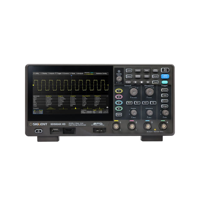
  • Siglent SDS814X HD 4 - ch Oscilloscope (100 MHz) - Elektor

    Siglent Siglent SDS814X HD 4-ch Oscilloscope (100 MHz)

    The Siglent SDS814X HD digital storage oscilloscope is based on 2 GSa/s, 12-bit Analog-Digital Converters and front ends with excellent noise floor performance. With a 100 MHz bandwidth, and a maximum record length of 50 Mpts, and the capability to analyze 4 analog channels alongside 16 digital channels, the SDS814X HD is perfectly suited for mixed signal analysis. Features 12-bit High Resolution 12-bit Analog-Digital Convertors with sample rate up to 2 GSa/s Front ends with 70 μVrms noise floor @ 100 MHz bandwidth 2/4 analog channels, up to 700 MHz bandwidth SPO technology Waveform capture rate up to 80,000 wfm/s (normal mode), and 500,000 wfm/s (sequence mode) Supports 256-level intensity grading and color temperature display modes. Up to 50 Mpts record length Digital trigger system Intelligent trigger: Edge, Slope, Pulse width, Window, Runt, Interval, Dropout, Pattern, Video (HDTV supported), Qualified, Nth edge, Delay, Setup/Hold time. Serial bus triggering and decoder, supports protocols I²C, SPI, UART, CAN, LIN. Segmented acquisition (Sequence) mode, dividing the maximum record length into multiple segments (up to 80,000), according to trigger conditions set by the user, with a very small dead time between segments to capture the qualifying event. History waveform record (History) function, the maximum recorded waveform length is 80,000 frames. Automatic measurements on 50+ parameters, supports statistics with histogram, track, trend, Gating measurement, and measurements on Math, History and Ref. 4 Math traces (2 Mpts FFT, addition, subtraction, multiplication, division, integration, differential, square root, etc.), supports formula editor. Abundant data analysis functions such as Search, Navigate, Counter, Bode plot and Power Analysis High Speed hardware-based Mask Test function, with Mask Editor tool for creating user-defined masks 16 digital channels (optional) 25 MHz waveform generator (optional) 7" TFT-LCD display with 1024 x 600 resolution; Capacitive touch screen supports multi-touch gestures. Interfaces include: USB Hosts, USB Device (USBTMC), LAN (VXI-11/Telnet/Socket), Pass/Fail, Trigger Out Built-in web server supports remote control over the LAN port using a web browser. Supports SCPI remote control commands. Supports external mouse and keyboard. Supports NTP. Specifications Analog Channels 4 Bandwidth 100 MHz Vertical resolution 12-bit Sample rate (Max.) One channel mode: 2 GSa/sTwo channel mode: 1 GSa/sFour channel mode: 500 MSa/s Memory depth (Max.) One channel mode: 50 Mpts/chTwo channel mode: 25 Mpts/chFour channel mode: 10Mpts/ch Waveform capture rate (Max.) Normal mode: 80,000 wfm/sSequence mode: 500,000 wfm/s Trigger type Edge, Slope, Pulse width, Window, Runt, Interval, Dropout, Pattern, Video, Qualified, Nth edge, Delay, Setup/Hold time, Serial Serial trigger and decode (Standard) I²C, SPI, UART, CAN, LIN Measurement 50+ parameters, statistics, histogram, trend, and track supported Math 4 traces 2 Mpts FFT, Filter, +, -, x, ÷, ∫dt, d/dt, √, Identity, Negation, Absolute, Sign, ex, 10x, ln, lg, Interpolation, MaxHold, MinHold, ERES, Average. Supports formula editor Data analysis Search, Navigate, History, Mask Test, Counter, Bode plot, and Power Analysis Digital channel (optional) 16-channel; maximum sample rate up to 1 GSa/s; record length up to 10 Mpts USB AWG module (option) One channel, 25 MHz, sample rate of 125 MHz, wave length of 16 kpts, isolated output I/O 2x USB 2.0 Host, USB 2.0 Device, 10/100 M LAN, Auxiliary output (TRIG OUT, PASS/FAIL), SBUS (Siglent MSO) Probe (Standard) Passive probe PB470 for each channel Display 7 TFT-LCD with capacitive touch screen (1024x600) Included 1x Siglent SDS814X Oscilloscope 4x Passive probe (100 MHz) PP510 1x Power cord (EU) 1x USB cable 1x Certificate of calibration 1x Quick start Downloads Datasheet Manual Programming guide

    € 586,85

Discover Elektor's measuring instruments collection

Elektor is the place for professionals and enthusiasts involved in electronics. We not only offer a source of education and inspiration, but also an extensive range of measuring instruments. These tools are essential for anyone who wants to take their projects to the next level of precision. Whether you are working on a complex design or testing a basic component, Elektor measuring instruments guarantee reliability and quality.

Essential measuring tools for your Projects

Elektor understands that good measuring instruments are the heart of every electronics project. That is why we have a wide range of oscilloscopes, multimeters, signal generators and more in our range. These tools have been carefully selected to meet the needs of both the hobbyist and the professional. With our measuring instruments you can tackle any electronics challenge with confidence.

In the rapidly changing world of electronics, it is crucial to have access to the latest technology. Our measuring instruments are equipped with the latest developments in electronics, so that you are always ahead of the curve. At Elektor you will find everything you need to support your electronics projects, from simple tools to advanced measuring equipment.

More than just measuring instruments

At Elektor it is more than just offering tools; we provide a community and a platform for knowledge sharing. In addition to measuring instruments, Elektor magazine offers ideas, information and inspiration for your next project. We are a source of innovation for electronics designers, both for professional use and for hobby projects.

Order your measuring instruments from Elektor

  • Quality and Diversity: An extensive range of high-quality measuring instruments.
  • Competitive Prices: Competitive prices with extra benefits for Elektor members.
  • Expertise and Support: Years of experience in electronics and a reliable source of knowledge and inspiration.

Prepare for success in your electronics projects with Elektor measuring instruments. Visit our collection today and find the perfect tools to suit your needs. With Elektor you choose quality, innovation and a community that is as passionate about electronics as you are.

Login

Forgot password?

Don't have an account yet?
Create account