
Branded
-
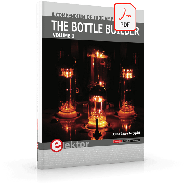
Elektor Digital The Bottle Builder (E-book)
The author, Johan Basse Bergqvist, is an engineer, a musician, and an audiophile with a knack for building projects that produce the desired results. The combination of these skills leads to a uniquely valuable perspective on audio design that is routinely reflected in the book and passed on to the readers. Several design projects are provided, 40 in total. The designs are explained, and the unique features or methods he uses are described in further detail. Each design includes detailed schematics and a complete parts list. Many of the projects also include layout documentation in the form of CAD photos of the PCB layouts. The range of projects is very diverse and includes something that will appeal to everyone. Stereo amplifiers, guitar and bass amplifiers, preamplifiers for phono, and microphones are all covered. Several variants for each type are included, and the power amplifier designs range from a few watts to several hundred watts, which meet almost any power level you might tackle.
€ 64,95
Members: € 58,46
-
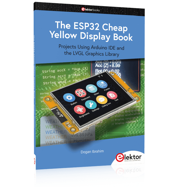
Elektor Publishing The ESP32 Cheap Yellow Display Book
Projects Using Arduino IDE and the LVGL Graphics Library The ESP32 is probably one of the most popular microcontrollers used by many people, including students, hobbyists, and professional engineers. Its low cost, coupled with rich features makes it a popular device to use in many projects. Recently, a board called the ESP32 Cheap Yellow Display (CYD for short) is available from its manufacturers. The board includes a standard ESP32 microcontroller together with a 320x240 pixel TFT display. Additionally, the board provides several connectors for interfaces such as GPIO, serial port (TX/RX), power and Ground. The inclusion of a TFT display is a real advantage as it enables users to design complex graphics-based projects without resorting to an external LCD or graphics displays. The book describes the basic hardware of the ESP32 CYD board and provides details of its on-board connectors. Many basic, simple, and intermediate-level projects are given in the book based on the ESP32 CYD, using the highly popular Arduino IDE 2.0 integrated development environment. The use of both the basic graphics functions and the use of the popular LVGL graphics library are discussed in the book and projects are given that use both types of approaches. All the projects given in the book have been tested and are working. The block diagram, circuit diagram, and the complete program listings and program descriptions of all the projects are given with explanations. Readers can use the LVGL graphics library to design highly popular eye-catching full-color graphics projects using widgets such as buttons, labels, calendars, keypads, keyboards, message boxes, spinboxes, sliders, charts, tables, menus, bars, switches, drop-down lists, animations, and many more widgets.
€ 34,95
Members: € 31,46
-
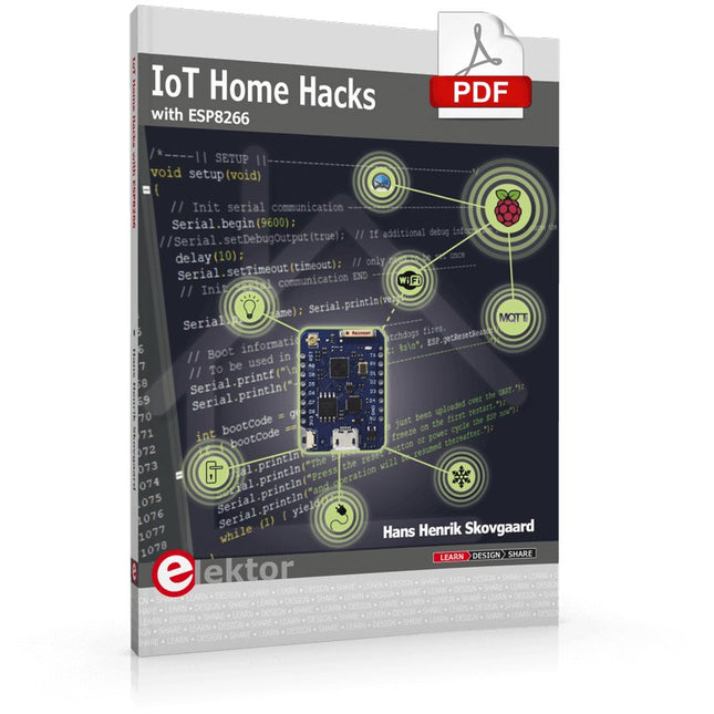
Elektor Digital IoT Home Hacks with ESP8266 (E-book)
There are many so-called 'Arduino compatible' platforms on the market. The ESP8266 – in the form of the WeMos D1 Mini Pro – is one that really stands out. This device includes WiFi Internet access and the option of a flash file system using up to 16 MB of external flash memory. Furthermore, there are ample in/output pins (though only one analogue input), PWM, I²C, and one-wire. Needless to say, you are easily able to construct many small IoT devices! This book contains the following builds: A colourful smart home accessory refrigerator controller 230 V power monitor door lock monitor and some further spin-off devices. All builds are documented together with relevant background information for further study. For your convenience, there is a small PCB for most of the designs; you can also use a perf board. You don’t need to be an expert but the minimum recommended essentials include basic experience with a PC, software, and hardware, including the ability to surf the Internet and assemble PCBs. And of course: A handle was kept on development costs. All custom software for the IoT devices and PCB layouts are available for free download from at Elektor.com.
€ 34,95
Members: € 31,46
-
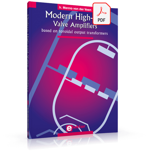
Elektor Digital Modern High-End Valve Amplifiers (E-book)
Valve Amplifiers are regarded by many to be the ne plus ultra when it comes to processing audio signals. The combination of classical technology and modern components has resulted in a revival of the valve amplifier. The use of toraidal-core output transformers, developed by the author over the past 15 years, has contributed to this revival. The most remarkable features of these transformers are their extremely wide frequency ranges and their very low levels of linear and nonlinear distortion. This book explains the whys and wherefores of toroidal output transformers at various technical levels, starting with elementary concepts and culminating in complete mathematical descriptions. In all of this, the interactions of the output valves, transformer and loudspeaker form the central theme. Next come the practical aspects. The schematic diagram of a valve amplifier often appears to be very simple at first glance, but anyone who has built a modern valve amplifier knows that a lot of critical details are hidden behind this apparent simplicity. These are discussed extensively, in connection with designs for amplifiers with output powers ranging from 10 to 100 watts. Finally, the author gives some attention to a number of special valve amplifiers, and to the theory and practice of negative feedback. In summary, this book offers innovative solutions for achieving perfect audio quality. Do-it-yourself builders, as well as persons who want to gain a deeper technical understanding of the complex world of audio transformers, valve amplifiers and audio signal processing, will find this book a rich and useful source of information.
€ 34,95
Members: € 31,46
-
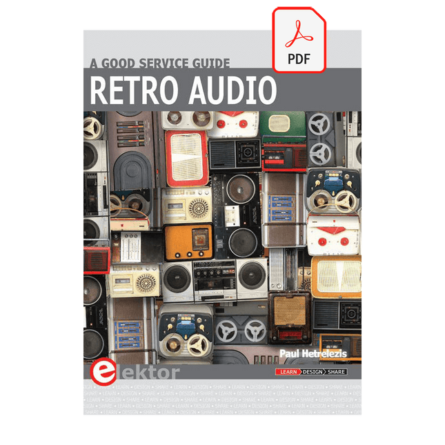
Elektor Digital Retro Audio (E-book)
The intention of this book is to offer the reader understandings, ideas and solutions from the perspective of a workbench technician and electronics hobbyist. It is a descriptive text with many tables of useful data, servicing tips and supplementary notes of not so common knowledge. Today there is a re-emerging, nostalgic interest in vinyl records and associated music entertainment gear. With this interest, there is a paralleled market for the repair of this gear. This ‘hands-on’ servicing guide opens with fundamental considerations of the work space of repair and servicing. This includes a comprehensive discussion of essential test equipment and tools. Two chapters are devoted to obtaining servicing information about repair and obtaining spare parts. A key chapter is on general diagnosis and testing and includes the discussion of resistance, capacitance and inductance. These electrical properties are regularly in the mind of the repairer, so understanding of them is a key objective of this book. The next chapter is about time saving repair techniques and ensuring quality repair. The remaining chapters discuss entertainment equipment itself. Each of the chapters begins with an orderly discussion of the theory of operation and common and not so common problems specific to the equipment. All chapters conclude with a summary.
€ 24,95
Members: € 22,46
-

Elektor Publishing The Connected Autonomous Vehicle and its Environment
An Introduction to Real and Reduced-Scale Autonomous Vehicles Want to cut through the hype and get to the core of autonomous and connected vehicles? Then this book is your clear, accessible guide to a complex and fast-moving field. Starting with Intelligent Transport Systems (ITS), it walks you through the essential foundations, including Advanced Driver Assistance Systems (ADAS) – the stepping stones to full autonomy. Explore how self-driving cars mimic human behavior through a loop of perception, analysis, decision, and action. Discover the key functions that make it possible: localization, obstacle detection, driver monitoring, cooperative awareness – and the most challenging of all, trajectory planning, across strategic, tactical, and operational levels. Will vehicles be connected? The debate is on – but the standards are already here. Learn how connectivity, infrastructure, and vehicles can work in synergy through the innovative concept of floating car data (FCD). Dive into real-world implementation: with embedded electronics account-ing for over 30% of a modern vehicle‘s cost, we unpack the architecture, coordination, and tools required to manage the complexity – brought to life with a hands-on case study. To finish, we open the door to the future: building your own 1:10 scale autonomous vehicle. No plug-and-play solutions – just the foundations for a collaborative, creative, and geek-friendly challenge. Let’s drive the future together.
€ 34,95
Members: € 31,46
-

Elektor Labs Elektor Low-Noise Lab Power Supply
The Elektor Low-Noise Lab Power Supply is a fully analogue, adjustable, medium-power symmetrical bench supply that contains no switching or digital components. It provides an output voltage adjustable between 0 V and ±22 V, and an output current adjustable from 0 A to 1 A. Because it avoids any form of switching circuitry, the design delivers extremely low noise. To display both output voltages and currents, four miniature moving-coil panel meters are used. Most modern laboratory power supplies and AC adapters employ switch-mode techniques. Even the best examples inevitably exhibit high-frequency ripple and other switching artefacts on their output, which can interfere with the testing of sensitive analogue circuits and disturb low-level measurements. To overcome this, the concept here is a completely analogue power supply. Although less efficient than its switch-mode counterparts, the reduced efficiency is of little importance for test-bench use and ensures cleaner, more reliable measurement results. Because many analogue circuits require a symmetrical supply, this design delivers positive and negative output voltages of equal magnitude. A small amount of adjustment is available to compensate for any imbalance. Naturally, a variable current-limit function is also included. The kit includes the components required to build the power supply, except for the transformers. Specifications Output Voltage 0…+22 V, 0, −22 V Output Current 0…+1 A, 0…−1 A Noise −85 dBV, (at 0.95 A/20 V, B = 22 kHz) −84 dBV (at 0.95 A/20 V, B > 500 kHz) Ripple 50 µVRMS (at 950 mA/20 V, B = 22 kHz, mainly 100 Hz component) Included 3x PCBs: Regulator (PCB-1), Mains Filter (PCB-2) and Transformer (PCB-3) All the components except the AC transformers 4x moving-coil meters Additional parts for wiring (wires, banana sockets, IEC Power entry module, etc.) Not included The three AC transformers An enclosure Parts List For the Regulator PCB (240386-1) Resistors (250 mW, 1%) R1 = 12 Ω R2, R8, R37, R62 = 1 MΩ R3, R7, R10, R13, R17, R20, R22, R30, R35, R42, R45, R47, R55, R60 = 100 Ω, 600 mW R4, R5 = 4.7 kΩ R6 = 100 kΩ R9, R12, R14, R36, R38, R39, R61, R63, R66, R72, R78, R79 = 10.0 kΩ, 600 mW R11 = 9.76 kΩ, 600 mW R15, R40 = 44.2 kΩ, 600 mW R16, R41, R77 = 1 kΩ R18, R43 = 1.5 kΩ, 1 W, 5% R19, R44 = 470 Ω, 1 W, 5% R21, R46 = 330 Ω, 600 mW R23, R24, R48, R49 = 1.0 Ω, 1 W R25, R50 = 1 kΩ, 1 W, 5% R26, R28, R51, R53 = 1.000 kΩ 0.1%, 15 ppm/C R27, R29, R52, R54 = 10.00 kΩ 0.1%, 15 ppm/C R31, R56 = 1.2 kΩ, 1 W, 5% R32, R57 = 47 kΩ R33, R58 = 270 Ω R34, R59 = 27 kΩ R64, R69 = 12.0 kΩ R65 = 3.0 kΩ, 600 mW R67, R80 = 470 Ω, 600 mW R68, R70 = 6.8 kΩ, 600 mW R71 = 30.0 kΩ,, 600 mW R73, R74, R75, R76 = 10 MΩ P1, P2, P3 = 10 kΩ, 200 mW, 20%, potentiometer, 1 turns, single, lin., panel mount P4, P5 = 500 Ω, 500 mW, 10%, trimmer, 25 turns, 3296Y-1-501LF Bourns P6, P7 = 10 kΩ, 500 mW, 10%, trimmer, 25 turns, 3296Y-1-501LF Bourns Capacitors C1 = 100 nF, 50 V, 10%, ceramic X7R, LS 5 mm C2, C3, C6, C7, C30 = 10 µF, 63V, 20%, LS 2.5 mm, 3000hours@105°C C4, C5, C8, C9, C13, C14, C18, C19, C23, C24, C28, C29, C31, C32, C38, C39 = 100 nF, 250 V, 10%, PET, LS 7.5 mm C10, C20 = 47 nF, 100 V, 5%, PET, LS 5 mm C11, C21 = 10 nF, 100 V, 5%, PET, LS 5 mm C12, C22 = 220 µF, 35 V, 20%, 0.024 Ω, LS2.5/3.5 mm, Ir 3.4 A, 2000hours@125°C, polymer C15, C25 = 120 µF, 50 V, 20%, ESR 0.02 Ω, Diam. 10 mm max., LS 5 mm C16, C26 = 15 nF, 100 V, 5%, PET, LS 5 mm C17, C27 = 47 nF, 100 V, 5%, PET, LS 5 mm C33, C34 = 22 µF, 50 V, 20%, LS 2 mm, 10000 hours @ 105°C C35, C36, C44, C45 = 1 µF, 100 V, 10%, LS 5 mm, ceramic X7R C37 = 100 uF, 50 V, 20%. LS 3.5 mm C40, C41, C42, C43, C46, C47, C48, C49 = 1000 µF, 50 V, 20%, LS 5/7.5 mm, Ir 3.32 A, 10000hours@105°C, D 16 mm C50, C51, C52, C53 = 47 nF, 100 V, 10%, ceramic X7R, LS 5 mm Inductors L1, L2 = 4.7 µH, 3.2 A, 0.033 Ω, LS 5 mm, RLB0914-4R7ML Bourns L3 = Commom mode choke, 14.5 mH, 3 A, SSRH24NH-30145 Kemet Semiconductors D1, D2, D3, D4, D5, D9, D10, D11, D15 = BAT85, DO-34 D6, D7, D12, D13 = SR560, DO-201AD D8, D14, D16 = 1N4148, DO-35 D17 = Zenerdiode, 5.6 V, 0.5 W, DO-41 D18, D19 = 1N4004, DO-41 D20, D21 D22, D23 = V30100CI-M3/P, dual common cathode, TO-220 D24 = Zener diode, 30 V, 1 W, DO-41 LED1, LED2 = LED, red, T-1 (3 mm) LED3, LED4 = LED, green, T-1 (3 mm) TVS1, TVS2 = BZW50-33B, R6 T1, T2, T4 = BC337.25, TO-92 T3 = NJW0302G, TO-3P T5, T6, T8 = BC327.25, TO-92 T7 = NJW0281G, TO-3P T9 = BD139, TO-126 (SOT-32) IC1 = LM334Z, TO-92 IC2 = LM4040AIZ-5.0/NOPB, TO-92 (TO-226AA-3) IC3, IC4 = OPA2992IDR, SOIC-8 IC5, IC6 = OPA4992IDR, SOIC-14 IC7 = OPA992IDBVR, SOT-23-5 IC8 = LM339N, DIP-14 IC9 = LM317, TO-220 IC10 = LM337, TO-220 Others F1, F2 = 5×20 mm fuse, 1.6 A, fast acting HS1, HS2 = Heatsink MC33271 (for T3/T7), 2.7°C/W, PCB mount, height 63.5 mm K1, K4 = 3-way screw terminal block, LS 3.5 mm, max. 1.5 mm² K2, K3 = 3-way screw terminal block, LS 3.5 mm, max. 1 mm² M1, M3 = Moving coil meter, Range 30 V, type 91C4, 45×45 mm M2, M4 = Moving coil meter, Range 1 A, type 91C4, 45×45 mm² RE1 = Relay DPDT,5V, UA2-5NU Miscellaneous 3× 3-way screw terminal block, LS 3.5 mm, max. 1 mm² (for P1, P2, P3) 4× Pin header, 1×2, vertical, pitch 2.54 mm (for LED1, LED2, LED3, LED4) 4× Pin socket, 1×2, vertical. pitch 2.54 mm (for LED1, LED2, LED3, LED4) 2× Heatsink FK222SA220, 20°C/W, PCB mount (for IC9 & IC10) 2× Mica thermal pad for TO-220, 12×18×0.05 mm (for IC9 & IC10) 2× Insulating bushing IB 6, TO-220 (for IC9 & IC10) 2× Ceramic thermal pad, 23×20×2 mm (for T3 & T7) 2× PCB Fuse Holder, for 5×20 mm fuse, 10 A (for F1, F2) 2× Cover for PCB Fuse Holder, transparent (for F1, F2) 2× 2-way screw terminal block, LS 3.5 mm, max. 1 mm² (for M1 & M3) 2× 2-way screw terminal block, LS 3.5 mm, max. 1.5 mm² (for M2 & M4) 8× M3 solder lug, thickness 0.35 mm (for M1…M4) M4 solder lug, thickness 0.35 mm (to connect 4 mm banana connectors) Screened cable, 1 pair, 2×24 AWG/0.22 mm², 1 m (for P1, P2 & P3) IC socket, DIP, 14 contacts (for IC8) M3 washer, plain, steel M3 screw, 16 mm, steel, pan head M3 nut M3 spring washer 50 mm M3 standoff, steel, male-female 12 mm M3 standoff, steel, male-female 10 mm M3 standoff, steel, male-female M3 screw, 8 mm, steel, pan head For the Mains Fiter PCB (240386-2) Resistor R1 = 220 kΩ, 1 W, 500 V, 5% Capacitors C1, C2 = 470 nF, 305 VAC, Class X2, 11 × 27 mm max., LS 15/22.5 mm C3, C4, C5, C6 = 2.2 nF, 300 VAC, Class Y2, 13 × 4 mm, LS 10 mm, PP Inductors L1, L2 = Common-mode choke, 6.8 mH, 1.7 A, TDK B82732R2172B030 Semiconductor MOV1 = TVS varistor, 300 VAC, S14K300 (230 VAC, B72214S0301K101) and SK14K150 (150 VAC, B72214S0151K101) Others K1, K2 = 3-way screw terminal block, LS 7.62 mm F1 = Time-delay fuse, 0.5 A (230 VAC) or 1 A (115 VAC) Miscellaneous 1× Fuse holder, 5×20 mm, 10 A, 500 VAC 1× Transparent fuse cover 4× 10 mm M3 standoff, steel, male–female 4× M3 screw, 8 mm, steel, pan head 4× M3 nut For the Transformer PCB (240386-3) Resistors R1, R2 = 2.7 kΩ, 600 mW, 1% R3 = 10.0 kΩ, 600 mW, 1% Capacitor C1 = 220 µF, 50 V, 20%, Ø10 mm, LS 5 mm, 4000 h @ 105°C Transformers (not included in this kit!) TR1, TR2, TR3 = 2×7 V, 25 VA, PCB-mounted toroid, 70060K Talema Semiconductors D1–D4 = 1N4148, DO-35 D5, D6 = 1N4004, DO-41 D7 = Zener 5.6 V, 1.3 W, DO-41 LED1 = LED, red, T-1 (3 mm) IC1, IC2 = MOC8021M, CTR ≥ 1000%, DIP-6 Others F1, F2, F3 = 160 mA time-delay fuse (230 VAC) or 315 mA time-delay fuse (115 VAC) K1 = 2-way screw terminal block, LS 7.62 mm K2 = 3-way screw terminal block, LS 3.5 mm, max 1.5 mm² K3, K4 = 3-way screw terminal block, LS 3.5 mm, max 1 mm² RE1, RE2 = Relay DPDT, 5 A/250 VAC / 24 VDC Miscellaneaous 1× Pin header 1×2, pitch 2.54 mm + matching socket for LED1 3× Fuse holder 5 × 20 mm, 10 A, 500 VAC + transparent cover 3× M4 screw, 8 mm, pan head + washer for TR1-TR3 8× M3 screw, 8 mm, pan head + nut + washer 8× 10 mm M3 standoff, steel, male–female 2× IC socket, DIP-6 for IC1 & IC2 Additional Parts 1 m red insulated wire, stranded, 1.5 mm² 0.5 m blue insulated wire, stranded, 1.5 mm² 0.5 m black insulated wire, stranded, 1.5 mm², 0.5 m 2 m red insulated wire, stranded, D 0.56 mm (0.25 mm²) 2 m black insulated wire, stranded, D 0.56 mm (0.25 mm²) 0.5 m Multicore Cable, Flexible, 3 Core, 0.75 mm² (24 x 0.2 mm) Red banana socket Black banana socket Blue banana socket Green banana socket IEC Power Entry Module with switch, IEC C14 3 crimp terminals, FASTON, 4.75 x 0.81 mm 3 knobs Links Elektor Labs JumpStarter Page Article (Part 1) Article (Part 2)
€ 299,00€ 249,00Best Price
-
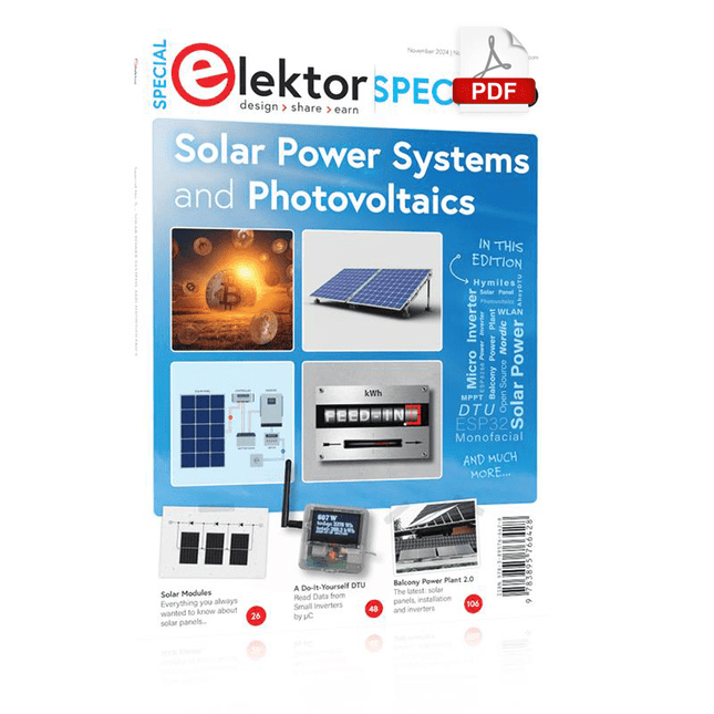
Elektor Digital Elektor Special: Solar Power Systems and Photovoltaics (PDF)
As demand for solar panel installation has risen sharply, especially for installations larger than balcony power plants, the order books of solar companies are full. If you ask for a quote today, you may have to wait a while, if your request isn't simply postponed indefinitely. Another consequence of the solar boom is that some companies are charging very high prices for installations. Yet there is an obvious and radical solution to the problem of excessive prices: Do it yourself, as the English say. The price of materials is currently affordable, and it's the ideal time for those who do the work themselves. They couldn't save more. Add to this the satisfaction of doing something useful, both economically and ecologically, and the pleasure of building yourself. In this special issue, you'll find a wide selection of Elektor assemblies, from solar panel controllers to solar water heaters and solar panel orientation systems. The issue also contains practical information on solar panel installation and the technology behind them. Finally, there are a number of articles on the subject of balcony power plants, from how to install them to how to connect them to the Internet... Contents BASICS Dimensioning Photovoltaic Panel ArraysAn introduction to photovoltaic energy and the commonest techniques,followed by simplified calculation models and setup guidelines. Light Sensor TechnologyMeasuring daylight using LEDs. Solar Power Made SimpleSolar charging with and without a controller. Cable Cross-sections and Energy Losses in Solar SystemsKey considerations on the minimum values to respect for electricalcurrent in solar panel cabling. Solar ModulesEverything you always wanted to know about solar panels... Ideal Diode ControllerDiode Circuits with Low Power Dissipation. TIPS Tracking for Solar Modules zBot Solar/Battery Power Supply Solar Cell Array Charger with Regulator Solar Cell Voltage Regulator Solar-Powered Night Light Alternative Solar Battery Charger PROJECTS Energy LoggerMeasuring and Recording Power Consumption. Tiny Solar SupplySunlight In, 3.3 V Out. A Do-It-Yourself DTURead Data from Small Inverters by μC. Solar ChargerPortable energy for people on the move. Solar Thermal Energy RegulatorMaximum power point tracking explored. 2-amp Maximum Power Tracking ChargerSolar Power To The Max. Computer-driven HeliostatFollow the sun or the stars. Garden LightingUsing solar cells. Solar Panel Voltage Converter for IoT DevicesYes we CAN exploit indoor lighting. Travel ChargerFree power in the mountains. Solar Cell Battery Charger/MonitorWith protection against deep discharge. Solar-powered Battery ChargerPIC12C671 avoids overcharging and deep charging. Converters for Photovoltaic PanelsContributed by TME (Transfer MultisortElektronik). Solar Charging RegulatorFor panels up to 53 watts. Solar-Powered ChargerFor lead-acid batteries. CAN Bus + Arduino for Solar PV Cell MonitoringDetect and locate serviceable panels in large arrays. Balcony Power Plant 2.0The latest: solar panels, installation and inverters
€ 14,95
Members: € 13,46
-
Elektor Digital Assembly Language Essentials (E-book)
A Guide to Powerful Programming for Embedded Systems You must be a well-rounded professional to excel in the ever-evolving, rapidly developing embedded design and programming industry. Simply put, when it comes to electronics design and programming, the more topics you can master, the more you’ll flourish at your workplace and at your personal workbench. This shouldn’t be a surprise, as the line between the skills of a hardware engineer and software engineer is blurring. The former should have a good grasp of programming in order to build efficient systems. The latter should understand the details of the design (whether it’s a physical or virtual application) for which he or she is writing code. Thus, to be successful, a modern professional electronics engineer must have a solid grasp of both hardware design and programming. Assembly Language Essentials is a matter-of-fact guide to Assembly that will introduce you to the most fundamental programming language of a processor. Unlike other resources about Assembly that focus exclusively on specific processors and platforms, this book uses the architecture of a fictional processor with its own hardware and instruction set. This enables you to consider the importance of Assembly language without having to deal with predetermined hardware or architectural restrictions. You’ll immediately find this thorough introduction to Assembly to be a valuable resource, whether you know nothing about the language or you have used it before. The only prerequisite is that you have a working knowledge of at least one higher-level programming language, such as C or Java. Assembly Language Essentials is an indispensible resource for electronics engineering professionals, academics, and advanced students looking to enhance their programming skills. The book provides the following, and more: An introduction to Assembly language and its functionality Significant definitions associated with Assembly language, as well as essential terminology pertaining to higher-level programming languages and computer architecture Important algorithms that may be built into high-level languages, but must be done the “hard way” in Assembly language — multiplication, division, and polynomial evaluation A presentation of Interrupt Service Routines with examples A free, downloadable Assembler program for experimenting with Assembly
€ 29,95
Members: € 26,96
-
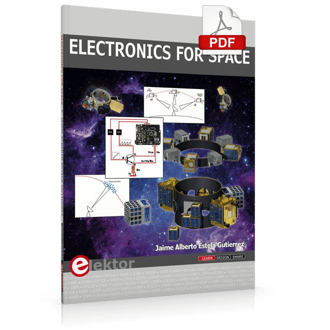
Elektor Digital Electronics for Space (E-book)
Space, the final frontier, will become more and more popular. The space industry is continually growing and new products and services will be required. Innovation is needed for the development of this industry. Today it is no longer possible to follow all the events in field of space. The space market is growing and activities are increasing, especially the market for small-satellites. This book wants to help close the gap and encourage electronic engineers to enter into the fascinating field of space electronics. One of the main difficulties is finding people with knowledge of space electronics design. Nowadays companies have to invest a lot of time and resources to instruct electronic engineers with no experience of space. Only a brief and basic introduction of this topic is typically achieved at university in space engineering lectures. Professionals with practical experience and the necessary theoretical knowledge are scarce. Companies from the space sector are searching for staff with knowledge of space electronics. This book will bring space closer aspiring to the space electronic hobbyists.
€ 24,95
Members: € 22,46
-

Elektor Bundles Learn Edge AI with Raspberry Pi
This hands-on bundle lets you build real Edge AI applications with the Raspberry Pi Raspberry Pi AI HAT+ (13 TOPS) The Raspberry Pi AI HAT+ (13 TOPS) is an expansion board designed for the Raspberry Pi 5, featuring an integrated Hailo AI accelerator. This add-on offers a cost-effective, efficient, and accessible approach to incorporating high-performance AI capabilities, with applications spanning process control, security, home automation, and robotics. The AI HAT+ connects via the Raspberry Pi 5’s PCIe Gen3 interface. When the Raspberry Pi 5 is running a current version of the Raspberry Pi OS, it automatically detects the onboard Hailo accelerator, making the neural processing unit (NPU) available for AI tasks. Additionally, the rpicam-apps camera applications included in Raspberry Pi OS seamlessly support the AI module, automatically using the NPU for compatible post-processing functions. Raspberry Pi Camera Module 3 Raspberry Pi Camera Module 3 is a compact camera from Raspberry Pi. It offers an IMX708 12-megapixel sensor with HDR, and features phase detection autofocus. Camera Module 3 is available in standard and wide-angle variants, both of which are available with or without an infrared cut filter. Camera Module 3 can be used to take full HD video as well as stills photographs, and features an HDR mode up to 3 megapixels. Its operation is fully supported by the libcamera library, including Camera Module 3’s rapid autofocus feature: this makes it easy for beginners to use, while offering plenty for advanced users. Camera Module 3 is compatible with all Raspberry Pi computers. Book: Edge AI Made Practical – AI Projects for the Raspberry Pi with the AI HAT+ Edge AI is transforming everyday devices by putting intelligence where it matters most: directly inside the hardware. With on-device inference, a camera can recognize a visitor instantly, a phone can translate speech without streaming audio to the cloud, and a wearable can detect anomalies in real time—fast, private, and reliable even when the network disappears. This book is your practical guide to building exactly those kinds of systems with the Raspberry Pi AI HAT+ and the Hailo-8L accelerator. You’ll start with clear foundations: core AI and machine-learning concepts, how neural networks work, and what truly distinguishes Edge AI from cloud AI—plus an honest look at ethical considerations and future impacts. This bundle contains: Book: Edge AI Made Practical Raspberry Pi AI HAT+ (13 TOPS) Raspberry Pi Camera Module 3 Active Cooler for Raspberry Pi 5 FPC Display Cable for Raspberry Pi 5 (300 mm) Elektor Component Kit 40-pin GPIO Header Traffic Light Module LED red 5 V with built-in resistor LED yellow 5 V with built-in resistor LED green 5 V with built-in resistor LED blue 5 V with built-in resistor Breadboard (400 Tie-points) 10 Dupont wires male-female DHT22 sensor module Servo motor Required Raspberry Pi 5
€ 169,95
Best Price
-

Elektor Digital Learning Digital Electronics (E-book)
With 20+ Practical Projects in Logic and Circuit Design This book is a practical guide to digital electronics, covering the essential components of modern digital systems: number systems, logic gates, Boolean algebra, combinational and sequential logic, and more. Through more than 20 structured projects, you’ll design and build digital systems using real-world components such as logic gates, multiplexers, decoders, flip-flops, counters, and shift registers. The projects range from basic LED logic circuits to digital locks, display systems, traffic light controllers, and timing-based designs. Selected projects introduce the use of tools such as CircuitVerse for circuit simulation, while several designs make use of 74HC-series logic devices, commonly used in digital hardware prototyping. Inside, you’ll find: Clear coverage of number systems and binary arithmetic Logic gate fundamentals and universal gate implementations Step-by-step projects using flip-flops, counters, and registers Real-world design with 74HC-series logic chips Techniques for designing combinational and sequential systems This book takes a design-first, application-driven approach to digital electronics—built around working circuits, tested logic, and hands-on experimentation.
€ 24,95
Members: € 22,46
-
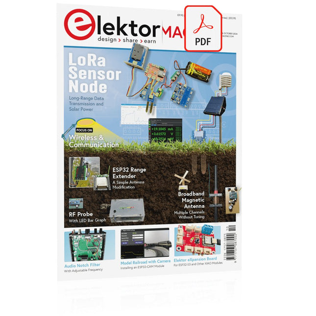
Elektor Digital Elektor September/October 2024 (PDF)
Elektor GREEN and GOLD members can download their digital edition here. Not a member yet? Click here. An Autonomous Sensor NodeLoRa-Based Data Transmission and Power by Solar Cells Elektor eXpansion Board v1.0For ESP32-S3 and other XIAO controller boards Model Railroad with CameraInstalling an ESP32 CAM Module Broadband Magnetic Antenna for Long WaveMultiple Channels Without Tuning TensorFlow Lite on Small MicrocontrollersA (Very) Beginner’s Point of View A Hub for RS-422 and RS-485 DevicesWire Your Bus Like a Star RF ProbeWith LED Bar Graph Starting Out in Electronics……Reviews More Opamp Circuits Open VarioThe Open-Source Multifunction Variometer for Paragliding From Life’s ExperienceAbout Taking Things for Granted AI-Based Water Meter Reading (Part 2)Get Your Old Meter Onto the IoT! ML-Based Pest DetectionSmart Agriculture Device With IoT Connectivity Why Anybus CompactCom Is the Ideal Choice for Embedded Industrial Communication IQRF Communication StandardReliability for Lossy, Low-Rate Wireless Mesh Networks How to Build a Smart Agricultural RobotEssential Technical Considerations and Challenges Audio Notch Filter with Adjustable FrequencyUniversal Solution for Suppressing Frequencies in Audio Applications The LeoINAGPS SystemGets Useful Insights on Your Electric Vehicle Solar-Powered LoRa NodeA Modular, Compact, and Versatile IoT Solution AWS for Arduino and Co. (2)Sending Data Using AWS IoT ExpressLink Err-lectronicsCorrections, Updates, and Readers’ Letters 2024: An AI OdysseyDesktop Versus Embedded Accelerators: A Look at Some Options ESP32 Range ExtenderA Simple Antenna Modification
€ 7,50
-

Elektor Digital Arduino 8-bit Sound Generation (E-book)
Arduinonext is an initiative powered by an electronics and microcontrollers specialist team aiming to help all those who are entering in the technology world, using the well-known Arduino platform to take the next step in electronics. We strive to bring you the necessary knowledge and experience for developing your own electronics applications; interacting with environment; measuring physical parameters; processing them and performing the necessary control actions. This is the first title in the 'Hands-On' series in which Arduino platform co-founder, David Cuartielles, introduces board programming, and demonstrates the making of an 8-bit Sound Generator.
€ 7,95
Members: € 7,16
-
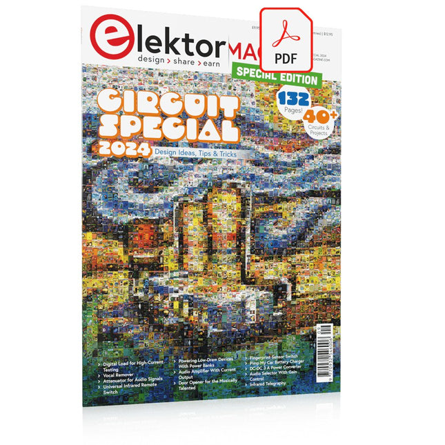
Elektor Digital Elektor Circuit Special 2024 PDF (EN)
Elektor GREEN and GOLD members can download their digital edition here. Not a member yet? Click here. Digital Load for High-Current TestingFrom Necessity to Innovation Vocal RemoverInstant Karaoke Circuit Audio A/B Selector With Gain ControlSwitches from Microphone to Line Inputs Better Charging for the LIR2032Be Kind to Your Coin Cells Touch Sensing Made SimpleA DIY Guide for Any Microcontroller Universal Infrared Remote SwitchA New Life for Old Remotes Microcontroller-Powered Moo BoxMaking Playful Sounds With a Microcontroller USB Battery Interface Powering Low-Draw Devices With Power BanksA “Stay Alive” Solution Small Class-A Audio Amplifier With Current OutputDrive Speakers with Current Instead of Voltage Pseudo-Balanced ModuleHigh CMRR with Unbalanced Audio Links Ni-MH Cells Automatic ChargerRefill All Your Battery Packs in One Go! Thyristor-Based Power Supply Protection Fingerprint Sensor SwitchA Useful Proof-of-Identity Device DC-DC 3-A Power ConverterUpgrade Your Fixed-Voltage Sources Remote Water Heater MonitorVoltage and Current Detection for AC Lines Attenuators for Audio Signals (1)Adjustable Via Jumpers Pimp My Car Battery Charger (Part 1)Don’t Throw It Away, Mod It! A Board for the Blue OnePCB for Alps Motorized Potentiometer with Feedback 50-Hz Reference from 60-Hz Mains VoltageHow to Use 50-Hz Electronics in 60-Hz Environments Digital IsolatorsRealizing Galvanic Isolation Easily Compact 12-W Hi-Fi Mono AmplifierSmall But Powerful LM386 Ramp Generator Three-Phase GeneratorWith Raspberry Pi Pico Door Opener for the Musically Talented Elektor Classic: Surf SynthesizerOcean Watersports Background Sound Generator (OWBSG) Pimp my Car Battery Charger (Part 2)Don’t Throw It Away, Mod It! Lamp Current MonitorWith a Raspberry Pi Pico Infrared Telegraphy Fnirsi SWM-10Repair Battery Packs With This Portable Intelligent Spot Welding Machine Stereo Audio Codec for the ESP32 and Co.No Need to Be Afraid of Audio Measurement Technology Tin Soldering TechniquesMake Them Well Right Away! Attenuators for Audio Signals (2)Switching Via Relays USB-C PowerDrawing Power from USB-C Power Adapters Three Circuits with Two and Three Counter ICs4017 ICs Working Together Active Components – The Diode A Timer For Ultra-Long DelaysSet It, and Forget It! Jack In and Jack OutA Useful Insert Option for Audio Circuits Power an ESP32 from a Single Li-ion Cell Hexadoku
€ 7,50
-
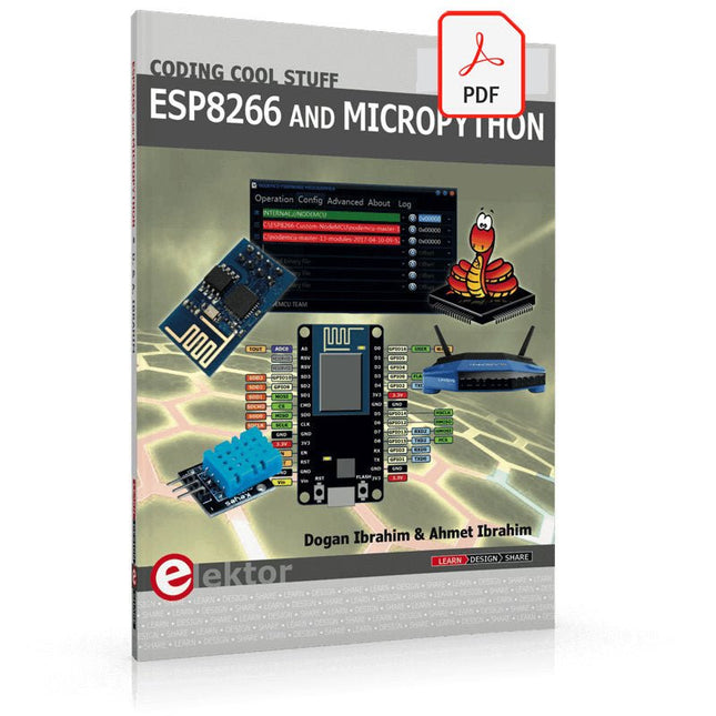
Elektor Digital ESP8266 and MicroPython (E-book)
Recently, the development of a tiny chip called the ESP8266 has made it possible to interface any type of microcontroller to a Wi-Fi AP. The ESP8266 is a low-cost tiny Wi-Fi chip having fully built-in TCP/IP stack and a 32-bit microcontroller unit. This chip, produced by Shanghai based Chinese manufacturer Espressif System, is IEEE 802.11 b/g/n Wi-Fi compatible with on-chip program and data memory, and general purpose input-output ports. Several manufacturers have incorporated the ESP8266 chip in their hardware products (e.g. ESP-xx, NodeMCU etc) and offer these products as a means of connecting a microcontroller system such as the Android, PIC microcontroller or others to a Wi-Fi. The ESP8266 is a low-power chip and costs only a few Dollars. ESP8266 and MicroPython – Coding Cool Stuff is an introduction to the ESP8266 chip and describes the features of this chip and shows how various firmware and programming languages such as the MicroPython can be uploaded to the chip. The main aim of the book is to teach the readers how to use the MicroPython programming language on ESP8266 based hardware, especially on the NodeMCU. Several interesting and useful projects are given in the e-book (pdf) to show how to use the MicroPython in NodeMCU type ESP8266 hardware: Project “What shall I wear today?”: You will be developing a weather information system using a NodeMCU development board together with a Text-to-Speech processor module. Project “The Temperature and Humidity on the Cloud”: You will be developing a system that will get the ambient temperature and humidity using a sensor and then store this data on the cloud so that it can be accessed from anywhere. Project “Remote Web Based Control”: You will be developing a system that will remotely control two LEDs connected to a NodeMCU development board using an HTTP Web Server application.
€ 29,95
Members: € 26,96
-
Elektor Digital C Programming for Embedded Microcontrollers (E-book)
Technology is constantly changing. New microcontrollers become available every year and old ones become redundant. The one thing that has stayed the same is the C programming language used to program these microcontrollers. If you would like to learn this standard language to program microcontrollers, then this book is for you! ARM microcontrollers are available from a large number of manufacturers. They are 32-bit microcontrollers and usually contain a decent amount of memory and a large number of on-chip peripherals. Although this book concentrates on ARM microcontrollers from Atmel, the C programming language applies equally to other manufacturer’s ARMs as well as other microcontrollers. Features of this book Use only free or open source software. Learn how to download, set up and use free C programming tools. Start learning the C language to write simple PC programs before tackling embedded programming - no need to buy an embedded system right away! Start learning to program from the very first chapter with simple programs and slowly build from there. No programming experience is necessary! Learn by doing - type and run the example programs and exercises. Sample programs and exercises can be downloaded from the Internet. A fun way to learn the C programming language. Ideal for electronic hobbyists, students and engineers wanting to learn the C programming language in an embedded environment on ARM microcontrollers.
€ 29,95
Members: € 26,96
-

Elektor Digital SDR with HackRF One & HackRF Pro (E-book)
Programming with GNU Radio HackRF is an open-source hardware platform developed by Great Scott Gadgets and serves as a versatile front end for software-defined radio (SDR). With HackRF One and its successor, HackRF Pro, users can develop their own SDR applications, build powerful receivers and transmitters, and tackle demanding RF measurement tasks. This book provides a practical introduction to the world of SDR. Step by step, the author shows how powerful SDR projects can be implemented with HackRF – from the fundamentals of RF technology to advanced applications using GNU Radio. In addition to working with SDR Sharp (SDR#), RadioConda, and GNU Radio, the book also covers the fundamentals of modern digital signal processing. Numerous experiments and easy-to-follow practical examples guide readers through topics such as AM, FM, and SSB reception, digital filters, shortwave radio, amateur radio, signal generators, and custom RF projects up to 6 GHz. Whether you are a maker, radio amateur, electronics enthusiast, or SDR beginner, this book provides solid knowledge, practical applications, and the motivation to creatively explore the possibilities of modern SDR technology.
€ 19,95
Members: € 17,96
-

Elektor Digital Controller Area Network Projects with ARM and Arduino (E-book)
This book details the use of the ARM Cortex-M family of processors and the Arduino Uno in practical CAN bus based projects. Inside, it gives a detailed introduction to the architecture of the Cortex-M family whilst providing examples of popular hardware and software development kits. Using these kits helps to simplify the embedded design cycle considerably and makes it easier to develop, debug, and test a CAN bus based project. The architecture of the highly popular ARM Cortex-M processor STM32F407VGT6 is described at a high level by considering its various modules. In addition, the use of the mikroC Pro for ARM and Arduino Uno CAN bus library of functions are described in detail. This book is written for students, for practising engineers, for hobbyists, and for everyone else who may need to learn more about the CAN bus and its applications. The book assumes that the reader has some knowledge of basic electronics. Knowledge of the C programming language will be useful in later chapters of the book, and familiarity with at least one microcontroller will be an advantage, especially if the reader intends to develop microcontroller based projects using CAN bus. The book should be useful source of reference to anyone interested in finding an answer to one or more of the following questions: What bus systems are available for the automotive industry? What are the principles of the CAN bus? What types of frames (or data packets) are available in a CAN bus system? How can errors be detected in a CAN bus system and how reliable is a CAN bus system? What types of CAN bus controllers are there? What are the advantages of the ARM Cortex-M microcontrollers? How can one create a CAN bus project using an ARM microcontroller? How can one create a CAN bus project using an Arduino microcontroller? How can one monitor data on the CAN bus?
€ 32,95
Members: € 29,66
-

Elektor Digital Controller Area Network Projects (E-book)
The Controller Area Network (CAN) was originally developed to be used as a vehicle data bus system in passenger cars. Today, CAN controllers are available from over 20 manufacturers, and CAN is finding applications in other fields, such as medical, aerospace, process control, automation, and so on. This book is written for students, for practising engineers, for hobbyists, and for everyone else who may be interested to learn more about the CAN bus and its applications. The aim of this book is to teach you the basic principles of CAN networks and in addition the development of microcontroller based projects using the CAN bus. In summary, this book enables the reader to: Learn the theory of the CAN bus used in automotive industry Learn the principles, operation, and programming of microcontrollers Design complete microcontroller based projects using the C language Develop complete real CAN bus projects using microcontrollers Learn the principles of OBD systems used to debug vehicle electronics You will learn how to design microcontroller based CAN bus nodes, build a CAN bus, develop high-level programs, and then exchange data in real-time over the bus. You will also learn how to build microcontroller hardware and interface it to LEDs, LCDs, and A/D converters. The book assumes that the reader has some knowledge on basic electronics. Knowledge of the C programming language will be useful in later chapters of the book, and familiarity with at least one member of the PIC series of microcontrollers will be an advantage, especially if the reader intends to develop microcontroller based projects using the CAN bus.
€ 29,95
Members: € 26,96
-

Elektor Digital The Connected Autonomous Vehicle and its Environment (E-book)
An Introduction to Real and Reduced-Scale Autonomous Vehicles Want to cut through the hype and get to the core of autonomous and connected vehicles? Then this book is your clear, accessible guide to a complex and fast-moving field. Starting with Intelligent Transport Systems (ITS), it walks you through the essential foundations, including Advanced Driver Assistance Systems (ADAS) – the stepping stones to full autonomy. Explore how self-driving cars mimic human behavior through a loop of perception, analysis, decision, and action. Discover the key functions that make it possible: localization, obstacle detection, driver monitoring, cooperative awareness – and the most challenging of all, trajectory planning, across strategic, tactical, and operational levels. Will vehicles be connected? The debate is on – but the standards are already here. Learn how connectivity, infrastructure, and vehicles can work in synergy through the innovative concept of floating car data (FCD). Dive into real-world implementation: with embedded electronics account-ing for over 30% of a modern vehicle‘s cost, we unpack the architecture, coordination, and tools required to manage the complexity – brought to life with a hands-on case study. To finish, we open the door to the future: building your own 1:10 scale autonomous vehicle. No plug-and-play solutions – just the foundations for a collaborative, creative, and geek-friendly challenge. Let’s drive the future together.
€ 29,95
Members: € 26,96
-
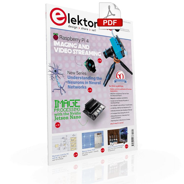
Elektor Digital Elektor September/October 2021 (PDF)
UNDERSTANDING THE NEURONS IN NEURAL NETWORKS (PART 1)Artificial Neurons EMC PRE-COMPLIANCE TEST FOR YOUR DC-POWERED PROJECT (PART 1)Dual DC LISN ELECTRONIC LOAD FOR DC AND ACUp to 400 V and 10 A (Peak) STARTING OUT IN ELECTRONICSEasier Than Imagined! ...Taking on the Choke! IMAGE PROCESSING WITH THE NVIDIA JETSON NANO (PART 1)The Hardware and Software AN IN-DEPTH LOOK AT MAINS TRANSFORMERSHow Do They Behave When They Are Switched On and Off? YES WE CAN WITH PICAN 3A CAN Bus HAT for the Raspberry Pi 4 BALCONY POWER PLANTDIY Solar Balcony = Speedy Payback! IMAGING AND VIDEO-STREAMING WITH A RASPBERRY PI 4The Raspberry Pi High-Quality Camera in Practice USING DISPLAYS IN RASPBERRY PI PROJECTSSample Chapter: Organic Light Emitting Diode Displays (OLED) HANDS ON THE PARALLAX PROPELLER 2 (PART 4)Sending Strings ELEKTOR @ 60A Look Back at Previous Septembers HOMELAB TOURSIn the Friesian Countryside, Where the Tubes Bloom ... HYBRIDSPeculiar Parts, the series A COMPASS ROSE USING THE GY-271Or Why We Move in Figures of Eight to Calibrate a Sensor FINDING YOUR FOOTPRINTCalculate the Carbon Footprint of Your Electronics ESP32-CONNECTED THERMOSTATKeep Your Wine at the Right Temperature! MAGNETIC LEVITATION THE DIGITAL WAYESP32 Pico Replaces the Analog Comparator ULTIMATE ARDUINO UNO HARDWARE MANUALSample Chapter: Main Microcontroller Bootloader MICROPYTHON FOR THE ESP32 AND FRIENDS (PART 2)Control Matrix Displays Easily MADMACHINE SWIFTIO BOARDModern Language Meets Modern Hardware FROM LIFE’S EXPERIENCEOn-Again, Off-Again Relationship HEXADOKUThe Original Elektorized Sudoku
€ 7,50
-
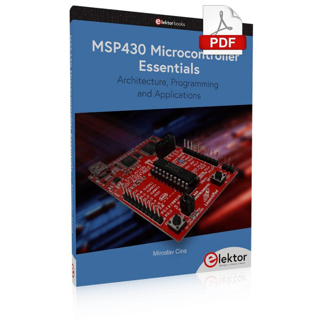
Elektor Digital MSP430 Microcontroller Essentials (E-book)
Architecture, Programming and Applications The MSP430 is a popular family of microcontrollers from Texas Instruments. In this book we will work with the smallest type, which is the powerful MSP430G2553. We will look at the capabilities of this microcontroller in detail, as it is well-suited for self-made projects because it is available in a P-DIP20 package. We will take a closer look at the microcontroller and then build, step by step, some interesting applications, including a 'Hello World' blinking LED and a nice clock application, which can calculate the day of the week based on the date. You also will learn how to create code for the MSP microcontroller in assembler. In addition to that, we will work with the MSP-Arduino IDE, which makes it quite easy to create fast applications without special in-depth knowledge of the microcontrollers. All the code used in the book is available for download from the Elektor website.
€ 32,95
Members: € 29,66
-

Elektor Publishing H0W2: Get Started with the MAX78000FTHR Development Board
Build your own AI microcontroller applications from scratch The MAX78000FTHR from Maxim Integrated is a small development board based on the MAX78000 MCU. The main usage of this board is in artificial intelligence applications (AI) which generally require large amounts of processing power and memory. It marries an Arm Cortex-M4 processor with a floating-point unit (FPU), convolutional neural network (CNN) accelerator, and RISC-V core into a single device. It is designed for ultra-low power consumption, making it ideal for many portable AI-based applications. This book is project-based and aims to teach the basic features of the MAX78000FTHR. It demonstrates how it can be used in various classical and AI-based projects. Each project is described in detail and complete program listings are provided. Readers should be able to use the projects as they are, or modify them to suit their applications. This book covers the following features of the MAX78000FTHR microcontroller development board: Onboard LEDs and buttons External LEDs and buttons Using analog-to-digital converters I²C projects SPI projects UART projects External interrupts and timer interrupts Using the onboard microphone Using the onboard camera Convolutional Neural Network
€ 39,95
Members: € 35,96


