
Search results for "arith OR matic OR s1 OR mu OR memory OR unit"
-

Elektor Bundles Arduino UNO Q (Bundle)
This bundle includes the Arduino UNO Q (2 GB) and the book "Arduino UNO Q and AI". The Arduino UNO Q is the first UNO board with a hybrid dual-brain architecture, combining a powerful Linux processor with a real-time microcontroller – bringing advanced computing and precise control together on one board. Powered by a Qualcomm Dragonwing QRB2210 MPU running Debian Linux and a STM32U585 MCU for real-time tasks, the UNO Q is built for next-generation applications. From Edge Computing and AI to robotics and automation, it delivers high performance without sacrificing ease of use. Simply connect your peripherals and get started – no extra hardware required. Features Dual-core architecture: Linux MPU + real-time MCU Qualcomm Dragonwing QRB2210 with Debian Linux support STM32U585 microcontroller for deterministic control Runs Arduino sketches via Zephyr OS Ideal for AI, IoT, robotics, and industrial projects Specifications Microprocessor (MPU) Qualcomm Dragonwing QRB2210:Quad-core Arm Cortex-A53 @ 2.0 GHzAdreno GPU 3D graphics accelerator2× ISP (13 MP + 13 MP or 25 MP) @ 30 fps Microcontroller (MCU) STM32U585Arm Cortex-M33 up to 160 MHz2 MB flash memory786 KB SRAM RAM 2 GB LPDDR4 Power Supply From USB-C connector 5 V max at 3 AInput Voltage (VIN): 7-24 V Storage 16 GB eMMC USB 1× USB-C port with host/device role switching, power role switch and video output Connectivity Wi-Fi 5 (2.4/5 GHz) with onboard antennaBluetooth 5.1 with onboard antenna Interfaces I²C/I³CSPIPWMCANUARTPSSIGPIOJTAGADC Video Video output support via USB-CMIPI DSI pins on JMEDIA header Extra 4× RGB user-controllable LEDs8×13 Blue LED Matrix1× Qwiic connector voltage 3V3, I²C1× User push-buttonJCTL: MPU Remote Debug connector Audio Microphone IN / Headphone OUT / Line OUT on JMISC MPU Operating System Linux Debian OS with upstream support Real-time Operating System Arduino Core on Zephyr OS Containerization Docker and Docker Compose support Support Operating Systems for Arduino App Lab Windows: Windows 10 or later (64-bit)macOS: macOS 11 or later (64-bit)Linux: Ubuntu 22.04 or later, and Debian Trixie (64-bit) Dimensions 68.85 × 53.34 mm (UNO form factor) Downloads Datasheet User Manual Pinout Schematics Book: Arduino UNO Q and AI – Learn to Build Intelligent Embedded Systems Build smarter embedded systems with Arduino UNO Q. This book gives you the tools, knowledge, and confidence to turn ideas into intelligent, working solutions using the Arduino UNO Q platform. Discover how to build intelligent embedded systems with the Arduino UNO Q and AI. Unlock the full potential of the Arduino UNO Q, a next-generation platform that combines the real-time power of the STM32U585 microcontroller with the flexibility of a Qualcomm Dragonwing QRB2210 microprocessor. Learn how to rapidly prototype real-world applications using the Arduino IDE for low-level embedded control and Python in Arduino App Lab for high-level development. Build confidence through hands-on projects that guide you step by step from basic board features to complete working systems. Explore ready-to-use, AI based Arduino App Lab examples and see how they can jump-start your development and reduce time to deployment. Step into the world of Edge AI with a clear, practical introduction to Edge Impulse Studio—no prior AI experience required. Follow a complete, real-world workflow to create a Keyword Spotting AI application, covering data collection, model training, optimization, and on-device inference using the Edge Impulse Studio. Bridge the gap between embedded systems and machine learning and learn how to bring intelligence directly onto your hardware. Perfect for embedded engineers, educators, students, and makers looking to stay ahead in AI-enabled product development. This bundle contains: Arduino UNO Q (2 GB) (normal price: €50) Book: Arduino UNO Q and AI (normal price: €35)
€ 84,95€ 74,95Best Price
-

Elektor Bundles Arduino Uno R4 WiFi (Bundle)
Book: Mastering the Arduino Uno R4 Based on the low-cost 8-bit ATmega328P processor, the Arduino Uno R3 board is likely to score as the most popular Arduino family member, and this workhorse has been with us for many years. Eleven years later, the long-overdue successor, the Arduino Uno R4, was released. It is built around a 48 MHz, 32-bit Arm Cortex-M4 microcontroller and provides significantly expanded SRAM and Flash memory. Additionally, a higher-precision ADC and a new DAC are added to the design. The Uno R4 board also supports the CAN Bus with an interface. Two versions of the board are available: Uno R4 Minima, and Uno R4 WiFi. This book is about using these new boards to develop many different and interesting projects with just a handful of parts and external modules. All projects described in the book have been fully tested on the Uno R4 Minima or the Uno R4 WiFi board, as appropriate. The project topics include the reading, control, and driving of many components and modules in the kit as well as on the relevant Uno R4 board, including LEDs 7-segment displays (using timer interrupts) LCDs Sensors RFID Reader 4x4 Keypad Real-time clock (RTC) Joystick 8×8 LED matrix Motors DAC (Digital-to-analog converter) LED matrix WiFi connectivity Serial UART CAN bus Infrared controller and receiver Simulators … all in creative and educational ways with the project operation and associated software explained in great detail. Arduino Uno R4 WiFi The Arduino Uno R4 is powered by the Renesas RA4M1 32-bit ARM Cortex-M4 processor, providing a significant boost in processing power, memory, and functionality. The WiFi version comes with an ESP32-S3 WiFi module in addition to the RA4M1, expanding creative opportunities for makers and engineers. The Arduino Uno R4 runs at 48 MHz, which provides a 3x increase over the popular Uno R3. Additionally, SRAM has been upgraded from 2 kB to 32 kB, and flash memory from 32 kB to 256 kB to support more complex projects. Responding to community feedback, the USB port is now USB-C, and the maximum power supply voltage has been raised to 24 V with an enhanced thermal design. The board includes a CAN bus and an SPI port, enabling users to reduce wiring and perform parallel tasks by connecting multiple shields. A 12-bit analog DAC is also provided on the board. Specifications Microcontroller Renesas RA4M1 (ARM Cortex-M4) USB USB-C Programming Port Pins Digital I/O Pins 14 Pins Analog input pins 6 DAC 1 RTC 1 PWM pins 6 Communication UART 1x I²C 1x SPI 1x Qwiic I²C connector 1x CAN 1x CAN Bus Power Circuit operating voltage 5 V Input voltage (VIN) 6-24 V DC Current per I/O Pin 8 mA Clock speed Main core 48 MHz Memory RA4M1 256 kB Flash, 32 kB RAM LED Matrix 12 x 8 (96 red LEDs) Dimensions 68.9 x 53.4 mm Downloads Datasheet Schematics This bundle contains: Book: Mastering the Arduino Uno R4 (normal price: €45) Arduino Uno R4 WiFi (normal price: €30)
€ 74,95€ 64,95Best Price
-

Elektor Bundles Learn Edge AI with Raspberry Pi
This hands-on bundle lets you build real Edge AI applications with the Raspberry Pi Raspberry Pi AI HAT+ (13 TOPS) The Raspberry Pi AI HAT+ (13 TOPS) is an expansion board designed for the Raspberry Pi 5, featuring an integrated Hailo AI accelerator. This add-on offers a cost-effective, efficient, and accessible approach to incorporating high-performance AI capabilities, with applications spanning process control, security, home automation, and robotics. The AI HAT+ connects via the Raspberry Pi 5’s PCIe Gen3 interface. When the Raspberry Pi 5 is running a current version of the Raspberry Pi OS, it automatically detects the onboard Hailo accelerator, making the neural processing unit (NPU) available for AI tasks. Additionally, the rpicam-apps camera applications included in Raspberry Pi OS seamlessly support the AI module, automatically using the NPU for compatible post-processing functions. Raspberry Pi Camera Module 3 Raspberry Pi Camera Module 3 is a compact camera from Raspberry Pi. It offers an IMX708 12-megapixel sensor with HDR, and features phase detection autofocus. Camera Module 3 is available in standard and wide-angle variants, both of which are available with or without an infrared cut filter. Camera Module 3 can be used to take full HD video as well as stills photographs, and features an HDR mode up to 3 megapixels. Its operation is fully supported by the libcamera library, including Camera Module 3’s rapid autofocus feature: this makes it easy for beginners to use, while offering plenty for advanced users. Camera Module 3 is compatible with all Raspberry Pi computers. Book: Edge AI Made Practical – AI Projects for the Raspberry Pi with the AI HAT+ Edge AI is transforming everyday devices by putting intelligence where it matters most: directly inside the hardware. With on-device inference, a camera can recognize a visitor instantly, a phone can translate speech without streaming audio to the cloud, and a wearable can detect anomalies in real time—fast, private, and reliable even when the network disappears. This book is your practical guide to building exactly those kinds of systems with the Raspberry Pi AI HAT+ and the Hailo-8L accelerator. You’ll start with clear foundations: core AI and machine-learning concepts, how neural networks work, and what truly distinguishes Edge AI from cloud AI—plus an honest look at ethical considerations and future impacts. This bundle contains: Book: Edge AI Made Practical Raspberry Pi AI HAT+ (13 TOPS) Raspberry Pi Camera Module 3 Active Cooler for Raspberry Pi 5 FPC Display Cable for Raspberry Pi 5 (300 mm) Elektor Component Kit 40-pin GPIO Header Traffic Light Module LED red 5 V with built-in resistor LED yellow 5 V with built-in resistor LED green 5 V with built-in resistor LED blue 5 V with built-in resistor Breadboard (400 Tie-points) 10 Dupont wires male-female DHT22 sensor module Servo motor Required Raspberry Pi 5
€ 169,95
Best Price
-

Elektor Labs Elektor Arduino Nano MCCAB Training Board
The Elektor Arduino Nano MCCAB Training Board contains all the components (incl. Arduino Nano) required for the exercises in the "Microcontrollers Hands-on Course for Arduino Starters", such as light-emitting diodes, switches, pushbuttons, acoustic signal transmitters, etc. External sensors, motors or assemblies can also be queried or controlled with this microcontroller training system. Specifications (Arduino Nano MCCAB Training Board) Power Supply Via the USB connection of the connected PC or an external power supply unit (not included) Operating Voltage +5 Vcc Input Voltage All inputs 0 V to +5 V VX1 and VX2 +8 V to +12 V (only when using an external power supply) Hardware periphery LCD 2x16 characters Potentiometer P1 & P2 JP3: selection of operating voltage of P1 & P2 Distributor SV4: Distributor for the operating voltagesSV5, SV6: Distributor for the inputs/outputs of the microcontroller Switches and buttons RESET button on the Arduino Nano module 6x pushbutton switches K1 ... K6 6x slide switches S1 ... S6 JP2: Connection of the switches with the inputs of the microcontroller Buzzer Piezo buzzer Buzzer1 with jumper on JP6 Indicator lights 11 x LED: Status indicator for the inputs/outputs LED L on the Arduino Nano module, connected to GPIO D13 JP6: Connection of LEDs LD10 ... LD20 with GPIOs D2 ... D12 Serial interfacesSPI & I²C JP4: Selection of the signal at pin X of the SPI connector SV12 SV9 to SV12: SPI interface (3.3 V/5 V) or I²C interface Switching output for external devices SV1, SV7: Switching output (maximum +24 V/160 mA, externally supplied) SV2: 2x13 pins for connection of external modules 3x3 LED matrix(9 red LEDs) SV3: Columns of the 3x3 LED matrix (outputs D6 ... D8) JP1: Connection of the rows with the GPIOs D3 ... D5 Software Library MCCABLib Control of hardware components (switches, buttons, LEDs, 3x3 LED matrix, buzzer) on the MCCAB Training Board Operating Temperature Up to +40 °C Dimensions 100 x 100 x 20 mm Specifications (Arduino Nano) Microcontroller ATmega328P Architecture AVR Operating Voltage 5 V Flash Memory 32 KB, of which 2 KB used by bootloader SRAM 2 KB Clock Speed 16 MHz Analog IN Pins 8 EEPROM 1 KB DC Current per I/O Pins 40 mA on one I/O pin, total maximum 200 mA on all pins together Input Voltage 7-12 V Digital I/O Pins 22 (6 of which are PWM) PWM Output 6 Power Consumption 19 mA Dimensions 18 x 45 mm Weight 7 g Included 1x Elektor Arduino Nano Training Board MCCAB 1x Arduino Nano
€ 79,95€ 69,95Best Price
-
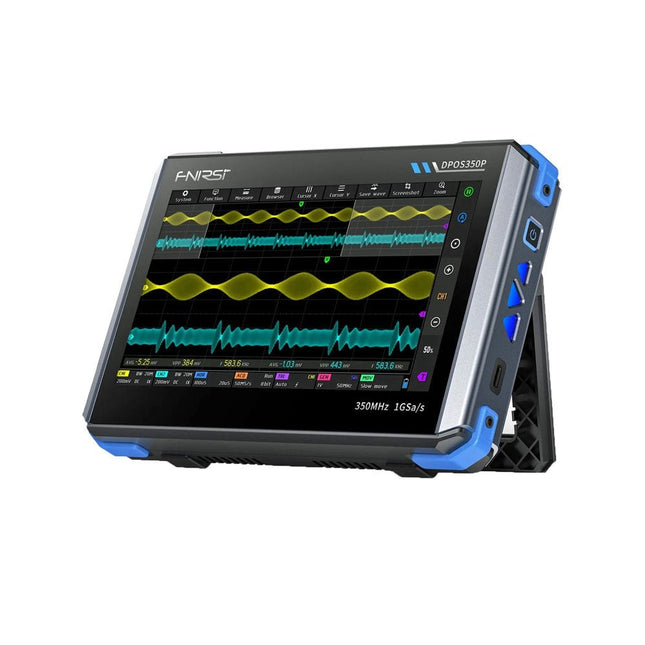
FNIRSI FNIRSI DPOS350P (4-in-1) 2-ch Tablet Oscilloscope (350 MHz) + Signal Generator + Frequency Response Analyzer + Spectrum Analyzer
2 Channels • 350 MHz • 1 GSa/s • 50,000 wfm/s • 7 inch Touchscreen The FNIRSI DPOS350P is a sleek 4-in-1 powerhouse in tablet form! This compact and portable device packs serious functionality: it combines a 2-channel oscilloscope (350 MHz), a signal generator (50 MHz), a frequency response analyzer (50 MHz), and a spectrum analyzer (200 kHz–350 MHz) – all in one unit. Whether you're in R&D, troubleshooting, or field testing, the DPOS350P delivers the tools you need to measure, generate, analyze, and visualize electronic signals with precision and clarity. Its responsive high-resolution touchscreen and intuitive controls make signal analysis fast, flexible and efficient. Features Powerful Multi-Function Integration 350 MHz 2-channel oscilloscope with 1 GSa/s real-time sampling 50 MHz signal generator with 14 standard + custom waveforms Spectrum analyzer (200 kHz–350 MHz): Perfect for EMI, RF & HF testing Frequency response analyzer (FRA) up to 50 MHz High-Performance Waveform Capture 50,000 wfm/s refresh rate for real-time signal clarity 350 MHz bandwidth (single-channel mode) Detects rare and low-probability anomalies Crisp Display & Smooth Operation 7" IPS touchscreen (1024 x 600 resolution) Switch between grayscale and color temperature display Easy to operate in various test environments Reliable, Protected & Fast-Charging High-voltage protection up to 400 V Fast charging with QC 18 W (full charge in 2 hours) Built for stable long-term operation Data Storage & Export Save up to 500 waveform records + 90 screenshots USB export for easy reporting and offline analysis Specifications General Display 7 inch (IPS full viewing angle) Resolution 1024 x 600 pixels Interaction mode Capacitive touch screen Total power consumption 10 W Power-on configuration 5 presets Charging QC 18 W, 12 V/1.5 A (USB-C) Battery 3.7 V, 8000 mAh lithium battery Battery life approx. 3 hours in operation, 5 hours standby Heat dissipation Air cooling Expansion interface USB data port Automatic shutdown 15~60 minutes / off Firmware upgrade Support .iso image upgrade Languages English / Portuguese / Russian / Chinese Dimensions 190 x 128 x 37 mm Oscilloscope Analog channels 2 Analog bandwidth 350 MHz Rise time 1ns Real-time sampling rate 1 GSa/s Memory depth 60 Kpts Input impedance 1 MΩ / 14PF Time base range 5ns ~ 50s Roll time base 50ms ~ 50s Vertical sensitivity 2 mV ~ 20 V (1X) Vertical range 16 mV ~ 160 V (1X) DC accuracy ±2% Time accuracy ±0.01% Input coupling DC / AC Probe attenuation 1X / 10X / 100X Hardware bandwidth limit 150M / 20M High resolution mode 8bit ~ 16bit Parameter measurements 12 types Cursor measurement Time, period, frequency, level, voltage Trigger detection Digital trigger Trigger channel CH1 / CH2 Trigger mode Auto / Single / Normal Trigger edge Rising edge / Falling edge Trigger suppression L1 ~ L3 Trigger level Manual / automatic 10% ~ 90% Screenshot storage 90 pictures Waveform storage 500 groups Background grid Display / hide Waveform movement Coarse adjustment / fine adjustment Overvoltage protection Withstand voltage 400 V Waveform brightness Adjustable Simple FFT display Yes Digital fluorescence Yes Color temperature display Yes X-Y mode Yes ZOOM time base Yes One-key automatic adjustment Yes One-key return to zero Yes Data browser Yes Signal Generator Waveform types 14 standard functions + captured waveform Frequency 0~50 MHz (sine wave only, other waveforms up to 10M/5M/3M) Amplitude 0~5 VPP Offset -2.5 V ~ +2.5V Duty cycle 0.1~99.9% Frequency resolution 1 Hz Amplitude resolution 1 mV Offset resolution 1 mV Duty cycle resolution 0.1% Customizable captured waveform 500 groups Frequency Response Analyzer (FRA) Excitation signal frequency 100 Hz ~ 50 MHz Excitation signal amplitude 0~5 VPP Excitation signal offset -2.5V ~ +2.5V Excitation frequency count 20~500 Cursor measurement Frequency / gain / phase Operating mode Single / cyclic System calibration Yes Spectrum Analyzer Conversion method FFT FFT length 4K ~ 32K Frequency range 200 KHz ~ 350 MHz Level range -60 dBmV ~ +260 dBmV Cursor measurement Frequency / amplitude Marking parameter Maximum energy harmonic Waterfall chart Yes 3D waterfall chart Yes Automatic adjustment Yes System calibration Yes Included 1x FNIRSI DPOS350P Oscilloscope (4-in-1) 2x 350 MHz Probes 1x QC 18 W Fast Charger (EU) 1x USB-C Cable 1x Alligator Clip 1x Storage Bag 1x Manual Downloads Manual Firmware
€ 309,00€ 259,00Best Price
-
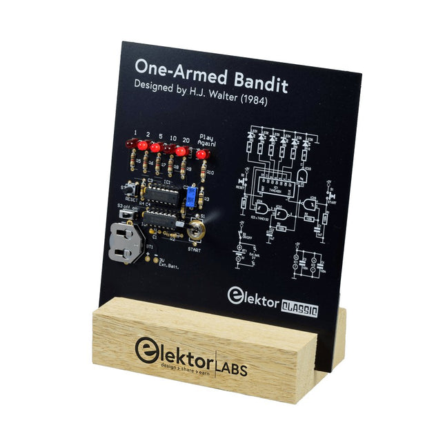
Elektor Labs Elektor One-armed Bandit
Pull Down Lever For Highest Score! This Elektor Circuit Classic from 1984 shows a playful application of CMOS 400x series logic ICs in combination with LEDs, a highly popular combination at the time. The project imitates a spinning-digit type slot machine. The Game To play the game, first agree on the number of rounds. Player 1 actuates the switch lever as long as desired and releases it. The LEDs then show the score which is the sum of the 50-20-10-5 digits lit up. If the Play Again! LED lights, Player 1 has another, “free” round. If not, it’s Player 2’s turn. The players keep tab of their scores, and the highest score wins. Features LEDs Indicate Score Multi-Player and Play Again! Elektor Heritage Circuit Symbols Tried & Tested by Elektor Labs Educational & Geeky Project Through-Hole Parts Only Included Printed Circuit Board All Components Wooden Stand Bill of Materials Resistors (5%, 250 mW) R1,R2,R3,R4 = 100kΩ R5,R6,R7,R8,R9,R10 = 1kΩ Capacitors C1 = 4.7nF, 10%, 50V, 5mm C2 = 4.7μF, 10%, 63V, axial C3,C4 = 100nF, 10 %, 50V, ceramic X7R, 5mm Semiconductors LED1-LED6 = red, 5mm (T1 3/4) IC1 = 74HC4024 IC2 = 74HC132 Miscellaneous S1 = switch, toggle, 21mm lever, SPDT, momentary S2 = switch, tactile, 24V, 50mA, 6x6mm S3 = switch, slide, SPDT IC1,IC2 = IC socket, DIP14 BT1 = PCB-mount CR2032 battery retainer clip Desktop Stand PCB 230098-1 Not included: BT1 = CR2032 coin cell battery
€ 39,95€ 15,98Best Price
-

FNIRSI FNIRSI 2D15P (3-in-1) 2-ch Oscilloscope (100 MHz) + Multimeter + Signal Generator
The FNIRSI 2D15P is a compact 3-in-1 test tool combining a 2-channel digital oscilloscope, True RMS multimeter, and waveform generator in one device. With a 4.3" capacitive touchscreen, 100 MHz bandwidth, 500 MSa/s sampling rate, and up to 1,200 fps capture speed, it’s ideal for fast troubleshooting, signal analysis, and electronics testing. Features Dual-Channel Input (100 MHz single-channel, 50 MHz dual-channel operation) Selectable Memory Depths 20 MHz Bandwidth Limit Grayscale & Color Temperature Visualization Math Operations (Add, Subtract, Multiply, Divide, etc.) XY Mode & Infinite Persistence Cursor Function & 13 Auto Measurements Auto / Normal / Single Trigger Modes True RMS Multimeter (19,999 Counts) 10 MHz DDS Signal Generator Specifications General Display 4.3" IPS Capacitive Touchscreen Operation Touch + Knob + Physical Buttons Charging USB-C (12 V/1 A fast charging) Battery 5000 mAh Lithium battery Dimensions 19.6 x 12.9 x 5.7 cm Weight 1.1 kg Oscilloscope Channels 2 Analog Bandwidth 100 MHz Sample Rate 500 MSa/s Memory Depth 10K, 100K, 1M Input Impedance 1 MΩ Timebase Range 5ns - 50s Vertical Sensitivity 10 mV - 10 V/div Max Input Voltage 800 V (x10 Probe) Trigger Mode Auto, Normal, Single Trigger Type Rising, Falling, Both Edges Coupling AC/DC Persistence min / 2s / 5s / 10s / 20s / 50s / ∞ Math Operations Yes Waveform Capture Yes Waveform Export Yes Cursor Measurement Yes Multimeter DC Voltage 1.9999V / 19.999V / 199.99V / 1000V AC Voltage 1.9999V / 19.999V / 199.99V / 750.0V DC Current 19.999mA / 199.99mA / 1.9999A / 9.999A AC Current 19.999mA / 199.99mA / 1.9999A / 9.999A Resistance 19.999MΩ / 1.9999MΩ / 199.99KΩ / 19.999KΩ / 1.9999KΩ / 199.99Ω Capacitance 999.9uF / 99.99uF / 9.999uF / 999.9nF / 99.99nF / 9.999nF / 9.999mF / 99.99mF Diode Yes Continuity Yes Signal Generator Channels 1 Frequency 0–10 MHz Amplitude 0.1–3.0 Vpp Duty Cycle 0–100% Included 1x FNIRSI 2D15P Oscilloscope 2x P6100 Oscilloscope Probes 1x Multimeter Probe 1x Alligator Clip Probe 1x USB Data Cable 1x Manual Downloads Manual Firmware V2.7.0.7
€ 209,00€ 179,95Best Price
-
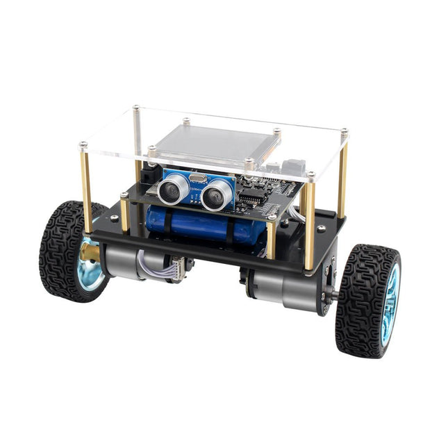
Elektor Labs Elektor Mini-Wheelie Self-Balancing Robot
Arduino-compatible, ESP32-controlled, 2-wheeled Balancing Robot The Elektor Mini-Wheelie is an experimental autonomous self-balancing robot platform. Based on an ESP32-S3 microcontroller, the self-balancing robot is fully programmable using the Arduino environment and open-source libraries. Its wireless capabilities allow it to be controlled remotely over Wi-Fi, Bluetooth or ESP-NOW or to communicate with a user or even another robot. An ultrasonic transducer is available for detecting obstacles. Its color display can be used for displaying cute facial expressions or, for the more down-to-earth users, cryptic debug messages. The robot comes as a neat kit of parts that you must assemble yourself. Everything is included, even a screwdriver. Note: The Mini-Wheelie is an educational development platform intended for learning, experimentation, and robotics development. It is not classified as a toy for children, and its features, documentation, and intended audience reflect this purpose. The product is aimed at students, educators, and developers who wish to explore robotics, programming, and hardware integration in an educational setting. Specifications ESP32-S3 microcontroller with Wi-Fi and Bluetooth MPU6050 6-axis Inertial Measurement Unit (IMU) Two independently controlled 12 V electric motors with tachometer Ultrasonic transducer 2.9" TFT color display (320 x 240) MicroSD card slot Battery power monitor 3S rechargeable Li-Po battery (11.1 V/2200 mAh) Battery charger included Arduino-based open-source software Dimensions (W x L x H): 23 x 8 x 13 cm Included 1x ESP32-S3 Mainboard + MPU6050 module 1x LCD board (2.9 inch) 1x Ultrasonic sensor 1x Battery pack (2200 mAh) 1x Battery charger 1x Motor tyre kit 1x Case board 1x Acrylic board 1x Screwdriver 1x Protective strip 1x Flex cable B (8 cm) 1x Flex cable A (12 cm) 1x Flex cable C 4x Copper column A (25 mm) 4x Copper column B (55 mm) 4x Copper column C (5 mm) 2x Plastic nylon column 8x Screws A (10 mm) 24x Screws B (M3x5) 8x Nuts 24x Metal washers 2x Zip tie 1x MicroSD card (32 GB) Downloads Documentation
€ 99,95€ 79,95Best Price
-
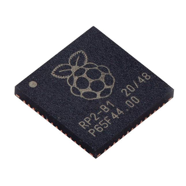
Raspberry Pi Foundation Raspberry Pi RP2040 Microcontroller (10 pcs)
Specifications Dual ARM Cortex-M0+ @ 133 MHz 264 kB on-chip SRAM in six independent banks Support for up to 16 MB of off-chip Flash memory via dedicated QSPI bus DMA controller Fully-connected AHB crossbar Interpolator and integer divider peripherals On-chip programmable LDO to generate core voltage 2x on-chip PLLs to generate USB and core clocks 30x GPIO pins, 4 of which can be used as analogue inputs Peripherals 2x UARTs 2x SPI controllers 2x I²C controllers 16x PWM channels USB 1.1 controller and PHY, with host and device support 8x PIO state machines What you'll get 10x bare RP2040 chips
€ 7,95€ 3,18Best Price
-

Great Scott Gadgets Great Scott Gadgets HackRF Pro SDR (100 kHz – 6 GHz) + FREE E-book
DEAL: Order the HackRF Pro now and get the new e-book "SDR with HackRF One & HackRF Pro" worth €20 for FREE! HackRF Pro is latest Software Defined Radio (SDR) from Great Scott Gadgets and the powerful successor to the legendary HackRF One. With a frequency range from 100 kHz to 6 GHz, it covers an enormous spectrum for transmitting and receiving radio signals. Designed as an open-source hardware platform, the HackRF Pro is the ideal tool for analyzing and developing modern wireless technologies. It can be used flexibly as a USB peripheral or programmed for standalone operation. Specifications Frequency: 100 kHz to 6 GHz Adjustable from 0 Hz to 7.1 GHz Half-duplex transceiver Up to 20 million samples per second 8-bit quadrature samples (8-bit I and 8-bit Q) Compatible with GNU Radio, SDR#, and more Software-configurable RX and TX gain and baseband filter Software-controlled RF port power (50 mA at 3.3 V) SMA RF connector SMA clock input and output for synchronization and triggering Convenient buttons for programming Internal pin headers for expansion High-Speed USB 2.0 with USB-C connector USB-powered Open source hardware Compared to its predecessor, HackRF Pro offers a variety of new features, including: Wider operating frequency range Improved RF performance with flatter frequency response USB-C connector Built-in TCXO crystal oscillator for superior timing stability Logic upgrade from a CPLD to a power-efficient FPGA Elimination of the DC spike Extended-precision mode with 16-bit samples for low sample rates (typical ENOB: 9-11) Half-precision mode with 4-bit samples at up to 40 Msps More RAM and flash memory for custom firmware Installed shielding around the radio section Trigger input and output accessible through clock connectors Cutout in the PCB provides space for future add-ons Improved power management Enhanced RF port protection Facility to hardware-disable transmit mode Full Compatibility: Thanks to its proven architecture, existing software for the HackRF One can also be used directly with the HackRF Pro. The HackRF Pro offers seamless backward compatibility while significantly increasing performance. Note: An antenna is not included. We recommend the ANT500 for the best experience. Included HackRF Pro SDR with plastic enclosure NEW e-book: SDR with HackRF One & HackRF Pro (normal price: €20) Downloads Documentation GitHub
€ 489,00€ 429,00Best Price


-
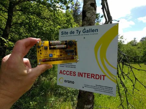
, by Clemens Valens Review: Detect Radiation with the MightyOhm Geiger Counter Kit
The MightyOhm Geiger Counter is a device for detecting beta and gamma radiation levels. Because radiation is so harmful, you may want to keep an...
-
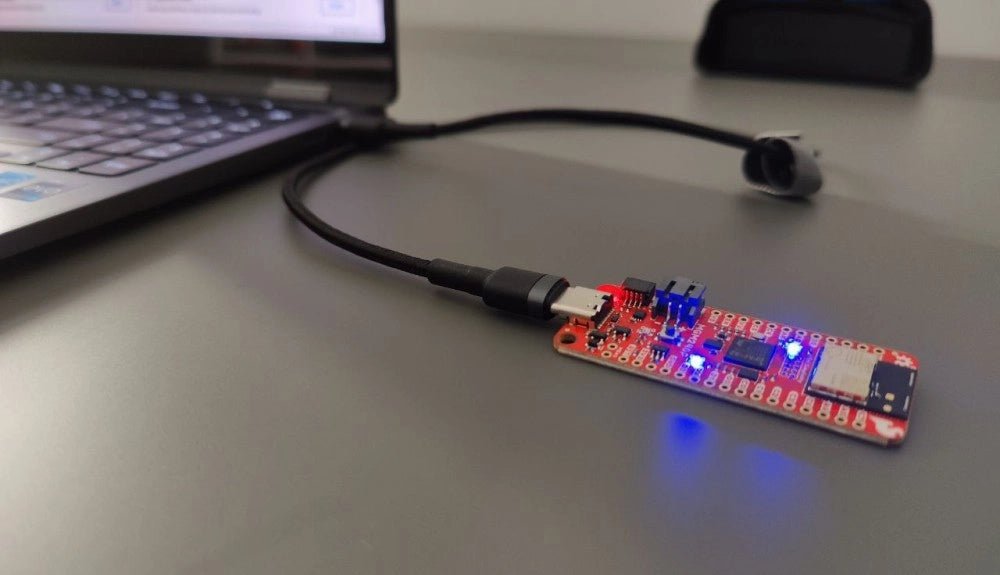
, by Saad Imtiaz SparkFun Thing Plus Matter (MGM240P): A Versatile Matter-Based IoT Development Board (Review)
The SparkFun Thing Plus Matter (MGM240P) is a versatile and feature-rich development board designed for creating Matter-based IoT devices. Matter, formerly known as Project CHIP...
