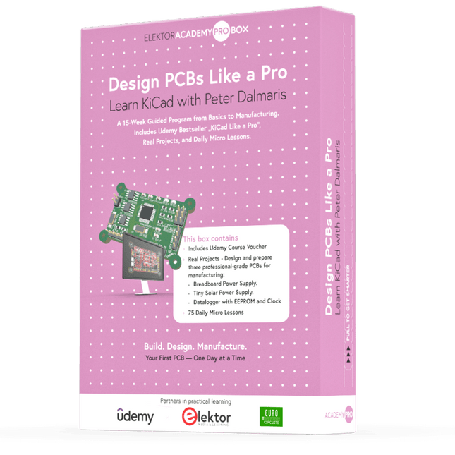
Learn KiCad with Peter Dalmaris
The Academy Pro Box "Design PCBs like a Pro" offers a complete, structured training programme in PCB design, combining online learning with practical application. Based on Peter Dalmaris’ KiCad course, the 15-week programme integrates video lessons, printed materials (2 books), and hands-on projects to ensure participants not only understand the theory but also develop the skills to apply it in practice.
Unlike standard courses, the Academy Pro Box provides a guided learning path with weekly milestones and physical components to design, test, and produce working PCBs. This approach supports a deeper learning experience and better knowledge retention.
The box is ideal for engineers, students, and professionals who want to develop practical PCB design expertise using open-source tools. With the added option to have their final project manufactured, participants complete the programme with real results – ready for use, testing, or further development.
Learn by doing
Build skills. Design real boards. Generate Gerbers. Place your first order. This isn’t just a course – it’s a complete project journey from idea to product.
You’ll walk away with:
Working knowledge of KiCad’s tools
Confidence designing your own PCBs
A fully manufacturable circuit board – made by you
What's inside the Box (Course)?
Both volumes of "KiCad Like a Pro" (valued at €105)
Vol 1: Fundamentals and Projects
Vol 2: Advanced Projects and Recipes
Coupon code to join the bestselling KiCad 9 online course by Peter Dalmaris on Udemy, featuring 20+ hours of video training. You'll complete three full design projects:
Breadboard Power Supply
Tiny Solar Power Supply
Datalogger with EEPROM and Clock
Voucher from Eurocircuits for the production of PCBs (worth €85 excl. VAT)
Learning Material (of this Box/Course)
15-Week Learning Program
▶ Click here to open
Week 1: Setup, Fundamentals, and First Steps in PCB Design
Week 2: Starting Your First PCB Project – Schematic Capture
Week 3: PCB Layout – From Netlist to Board Design
Week 4: Design Principles, Libraries, and Workflow
Week 5: Your First Real-World PCB Project
Week 6: Custom Libraries – Symbols, Footprints, and Workflow
Week 7: Advanced Tools – Net Classes, Rules, Zones, Routing
Week 8: Manufacturing Files, BOMs, and PCB Ordering
Week 9: Advanced Finishing Techniques – Graphics, Refinement, and Production Quality
Week 10: Tiny Solar Power Supply – From Schematic to Layout
Week 11: Tiny Solar Power Supply – PCB Layout and Production Prep
Week 12: ESP32 Clone Project – Schematic Design and Layout Prep
Week 13: ESP32 Clone – PCB Layout and Manufacturing Prep
Week 14: Final Improvements and Advanced Features
Week 15: Productivity Tools, Simulation, and Automation
KiCad Course with 18 Lessons on Udemy (by Peter Dalmaris)
▶ Click here to open
Introduction
Getting started with PCB design
Getting started with KiCad
Project: A hands-on tour of KiCad (Schematic Design)
Project: A hands-on tour of KiCad (Layout)
Design principles and PCB terms
Design workflow and considerations
Fundamental KiCad how-to: Symbols and Eeschema
Fundamental KiCad how-to: Footprints and Pcbnew
Project: Design a simple breadboard power supply PCB
Project: Tiny Solar Power Supply
Project: MCU datalogger with build-in 512K EEPROM and clock
Recipes
KiCad 9 new features and improvements
Legacy (from previous versions of KiCad)
KiCad 7 update (Legacy)
(Legacy) Gettings started with KiCad
Bonus lecture
About the Author
Dr. Peter Dalmaris, PhD is an educator, an electrical engineer and Maker. Creator of online video courses on DIY electronics and author of several technical books. As a Chief Tech Explorer since 2013 at Tech Explorations, the company he founded in Sydney, Australia, Peter's mission is to explore technology and help educate the world.
What is Elektor Academy Pro?
Elektor Academy Pro delivers specialized learning solutions designed for professionals, engineering teams, and technical experts in the electronics and embedded systems industry. It enables individuals and organizations to expand their practical knowledge, enhance their skills, and stay ahead of the curve through high-quality resources and hands-on training tools.
From real-world projects and expert-led courses to in-depth technical insights, Elektor empowers engineers to tackle today’s electronics and embedded systems challenges. Our educational offerings include Academy Books, Pro Boxes, Webinars, Conferences, and industry-focused B2B magazines – all created with professional development in mind.
Whether you're an engineer, R&D specialist, or technical decision-maker, Elektor Academy Pro bridges the gap between theory and practice, helping you master emerging technologies and drive innovation within your organization.
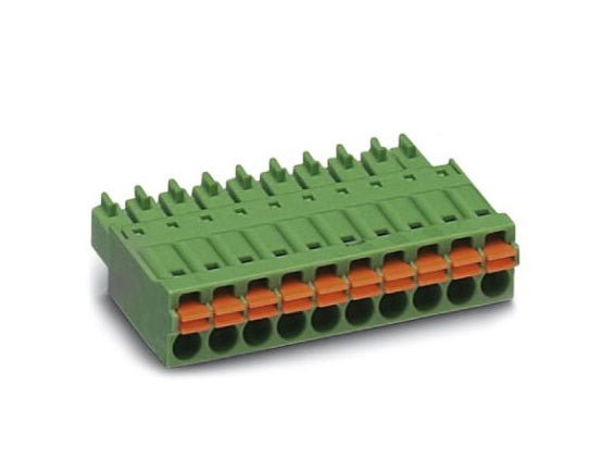
This 14-way MonoDAQ-compatible connector allows the user to create, reuse and archive test fixtures instead of rewiring the connector furnished with the MonoDAQ everytime a measurement or test has to be repeated. Helps the user to build a library of plug-and-play test setups. Features Time saving push-in connection, tools not required Defined contact force ensures that contact remains stable over the long term Intuitive use through colour coded actuation lever Operation and conductor connection from one direction enable integration into front of device All necessary technical data can be found here.
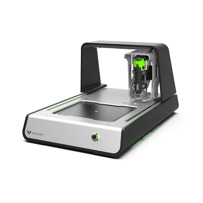
Solder Paste Dispensing and Reflow All-in-One
The Voltera V-One creates two-layer prototype circuit boards on your desk. Gerber files go in, printed circuit boards come out. The dispenser lays down a silver-based conductive ink to print your circuit right before your eyes. Assembling traditional and additive boards is easy with the V-One’s solder paste dispensing and reflow features. Simply mount your board on the print bed and import your Gerber file into Voltera’s software.
No more stencils required
Voltera’s software is designed to be understood easily. From importing your Gerber files to the moment you press print, the software safely walks you through each step.
Compatible with EAGLE, Altium, KiCad, Mentor Graphics, Cadence, DipTrace, Upverter.
Included
V-One PCB printer
V-One dispenser
V-One probe
Nozzle pack
Tip caps
3 x 4" FR1 substrate pack
2 x 3" FR1 substrate pack
Substrate clamps
Thumbscrew pack
Hello World kit
Solder wire
Tweezers
Power supply
Power adapter
Cables
User guides
Downloads
Specifications
V-One Software
Manuals
Safety Datasheets
Technical Datasheets
Voltera CAM file for EAGLE
Substrates and Templates
More Info
Frequently Asked Questions
More from the Voltera community
Technical Specifications
Printing Specifications
Minimum trace width
0.2 mm
Minimum passive size
1005
Minimum pin-to-pin pitch (conductive ink)
0.8 mml
Minimum pin-to-pin pitch (solder paste)
0.5 mml
Resistivity
12 mΩ/sq @ 70 um height
Substrate material
FR4
Maximum board thickness
3 mm
Soldering Specifications
Solder paste alloy
Sn42/Bi57.6/Ag0.4
Solder wire alloy
SnBiAg1
Soldering iron temperature
180-210°C
Print Bed
Print area
135 x 113.5 mm
Max. heated bed temperature
240°C
Heated bed ramp rate
~2°C/s
Footprint
Dimensions
390 x 257 x 207 mm (L x W x H)
Weight
7 kg
Computing Requirements
Compatible operating systems
Windows 7 or higher, MacOS 10.11 or higher
Compatible file format
Gerber
Connection type
Wired USB
Certification
EN 61326-1:2013
EMC requirements
IEC 61010-1
Safety requirements
CE Marking
Affixed to the Voltera V-One printers delivered to European customers
Designed and assembled in Canada.
More technical information
Quickstart
Explore Flexible Printed Electronics on the V-One
Voltera V-One Capabilities Reel
Voltera V-One PCB Printer Walkthrough
Unpacking the V-One
V-One: Solder Paste Dispensing and Reflow All-in-One
Voltera @ Stanford University's Bao Research Group: Robotic Skin and Stretchable Sensors
Voltera @ Princeton: The Future of Aerospace Innovation
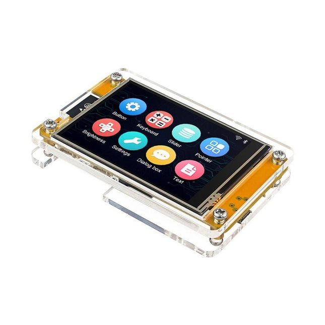
This development board (also known as "Cheap Yellow Display") is powered by the ESP-WROOM-32, a dual-core MCU with integrated Wi-Fi and Bluetooth capabilities. It operates at a main frequency of up to 240 MHz, with 520 KB SRAM, 448 KBROM, and a 4 MB Flash memory. The board features a 2.8-inch display with a resolution of 240x320 and resistive touch.
Furthermore, the board includes a backlight control circuit, touch control circuit, speaker drive circuit, photosensitive circuit, and RGB-LED control circuit. It also provides a TF card slot, serial interface, DHT11 temperature and humidity sensor interface, and additional IO ports.
The module supports development in Arduino IDE, ESP-IDE, MicroPython, and Mixly.
Applications
Image transmission for Smart Home device
Wireless monitoring
Smart agriculture
QR wireless recognition
Wireless positioning system signal
And other IoT applications
Specifications
Microcontroller
ESP-WROOM-32 (Dual-core MCU with integrated Wi-Fi and Bluetooth)
Frequency
Up to 240 MHz (computing power is up to 600 DMIPS)
SRAM
520 KB
ROM
448 KB
Flash
4 MB
Operating voltage
5 V
Power consumption
approx. 115 mA
Display
2.8-inch color TFT screen (240x320)
Touch
Resistive Touch
Driver chip
ILI9341
Dimensions
50 x 86 mm
Weight
50 g
Included
1x ESP32 Dev Board with 2.8" Display and acrylic Shell
1x Touch pen
1x Connector cable
1x USB cable
Downloads
GitHub
This e-book (pdf), a software-only follow up to the best-selling Elektor Visual Studio C# range of books, is aimed at Engineers, Scientists and Enthusiasts who want to learn about the C# language and development environment.
It covers steps from installation, the .NET framework and object oriented programming, through to more advanced concepts including database applications, threading and multi-tasking, internet/network communications and writing DLLs. The DirectX chapters also include video capture. The e-book concludes with several chapters on writing Android applications in C# using the Xamarin add-on.
This e-book is based on the Visual Studio 2015 development environment and latest C# additions including WPF applications, LINQ queries, Charts and new commands such as await and async. The latest Visual Studio debugging features (PerfTips, Diagnostic Tool window and IntellTrace) are covered. Finally, the Android chapters include GPS, E-mail and SMS applications.
Additionally, the e-book provides free on-line access to extensive, well-documented examples — in a try for yourself style — together with links to the author’s videos, guiding you through the necessary steps to get the expected results.
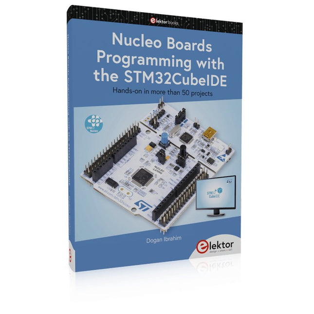
Hands-on in more than 50 projects
STM32 Nucleo family of processors are manufactured by STMicroelectronics. These are low-cost ARM microcontroller development boards. This book is about developing projects using the popular STM32CubeIDE software with the Nucleo-L476RG development board. In the early Chapters of the book the architecture of the Nucleo family is briefly described.
The book covers many projects using most features of the Nucleo-L476RG development board where the full software listings for the STM32CubeIDE are given for each project together with extensive descriptions. The projects range from simple flashing LEDs to more complex projects using modules, devices, and libraries such as GPIO, ADC, DAC, I²C, SPI, LCD, DMA, analogue inputs, power management, X-CUBE-MEMS1 library, DEBUGGING, and others. In addition, several projects are given using the popular Nucleo Expansion Boards. These Expansion Boards plug on top of the Nucleo development boards and provide sensors, relays, accelerometers, gyroscopes, Wi-Fi, and many others. Using an expansion board together with the X-CUBE-MEMS1 library simplifies the task of project development considerably.
All the projects in the book have been tested and are working. The following sub-headings are given for each project: Project Title, Description, Aim, Block Diagram, Circuit Diagram, and Program Listing for the STM32CubeIDE.
In this book you will learn about
STM32 microcontroller architecture;
the Nucleo-L476RG development board in projects using the STM32CubeIDE integrated software development tool;
external and internal interrupts and DMA;
DEBUG, a program developed using the STM32CubeIDE;
the MCU in Sleep, Stop, and in Standby modes;
Nucleo Expansion Boards with the Nucleo development boards.
What you need
a PC with Internet connection and a USB port;
STM32CubeIDE software (available at STMicroelectronics website free of charge)
the project source files, available from the book’s webpage hosted by Elektor;
Nucleo-L476RG development board;
simple electronic devices such as LEDs, temperature sensor, I²C and SPI chips, and a few more;
Nucleo Expansion Boards (optional).
The LuckFox Pico Ultra is a compact single-board computer (SBC) powered by the Rockchip RV1106G3 chipset, designed for AI processing, multimedia, and low-power embedded applications.
It comes equipped with a built-in 1 TOPS NPU, making it ideal for edge AI workloads. With 256 MB RAM, 8 GB onboard eMMC storage, integrated WiFi, and support for the LuckFox PoE module, the board delivers both performance and versatility across a wide range of use cases.
Running Linux, the LuckFox Pico Ultra supports a variety of interfaces – including MIPI CSI, RGB LCD, GPIO, UART, SPI, I²C, and USB – providing a simple and efficient development platform for applications in smart home, industrial control, and IoT.
Specifications
Chip
Rockchip RV1106G3
Processor
Cortex-A7 1.2 GHz
Neural Network Processor (NPU)
1 TOPS, supports int4, int8, int16
Image Processor (ISP)
Max input 5M @30fps
Memory
256 MB DDR3L
WiFi + Bluetooth
2.4GHz WiFi-6 Bluetooth 5.2/BLE
Camera Interface
MIPI CSI 2-lane
DPI Interface
RGB666
PoE Interface
IEEE 802.3af PoE
Speaker interface
MX1.25 mm
USB
USB 2.0 Host/Device
GPIO
30 GPIO pins
Ethernet
10/100M Ethernet controller and embedded PHY
Default Storage Medium
eMMC (8 GB)
Included
1x LuckFox Pico Ultra W
1x LuckFox PoE module
1x IPX 2.4G 2 db antenna
1x USB-A to USB-C cable
1x Screws pack
Downloads
Wiki
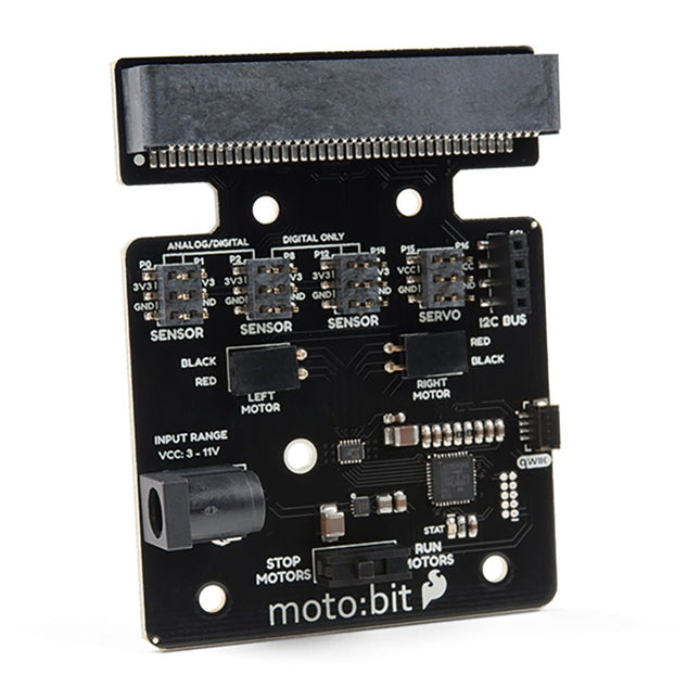
Onboard each moto:bit are multiple I/O pins, as well as a vertical Qwiic connector, capable of hooking up servos, sensors and other circuits. At the flip of the switch, you can get your micro:bit moving! The moto:bit connects to the micro:bit via an updated SMD, edge connector at the top of the board, making setup easy. This creates a handy way to swap out micro:bits for programming while still providing reliable connections to all of the different pins on the micro:bit. We have also included a basic barrel jack on the moto:bit that is capable of providing power to anything you connect to the carrier board. Features More reliable Edge connector for easy use with the micro:bit Full H-Bridge for control of two motors Control servo motors Vertical Qwiic Connector I²C port for extending functionality Power and battery management onboard for the micro:bit
The FRDM-MCXN947 is a compact and versatile development board designed for rapid prototyping with MCX N94 and N54 microcontrollers. It features industry-standard headers for easy access to the MCU's I/Os, integrated open-standard serial interfaces, external flash memory, and an onboard MCU-Link debugger.
Specifications
Microcontroller
MCX-N947 Dual Arm Cortex-M33 cores @ 150 MHz each with optimized performance efficiency, up to 2 MB dual-bank flash with optional full ECC RAM, External flash
Accelerators: Neural Processing Unit, PowerQuad, Smart DMA, etc.
Memory Expansion
*DNP Micro SD card socket
Connectivity
Ethernet Phy and connector
HS USB-C connectors
SPI/I²C/UART connector (PMOD/mikroBUS, DNP)
WiFi connector (PMOD/mikroBUS, DNP)
CAN-FD transceiver
Debug
On-board MCU-Link debugger with CMSIS-DAP
JTAG/SWD connector
Sensor
P3T1755 I³C/I²C Temp Sensor, Touch Pad
Expansion Options
Arduino Header (with FRDM expansion rows)
FRDM Header
FlexIO/LCD Header
SmartDMA/Camera Header
Pmod *DNP
mikroBUS
User Interface
RGB user LED, plus Reset, ISP, Wakeup buttons
Included
1x FRDM-MCXN947 Development Board
1x USB-C Cable
1x Quick Start Guide
Downloads
Datasheet
Block diagram
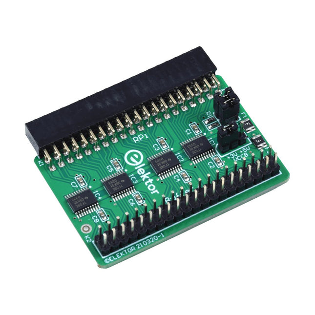
When you experiment with the Raspberry Pi on a regular basis and you connect a variety of external hardware to the GPIO port via the header you may well have caused some damage in the past. The Elektor Raspberry Pi Buffer Board is there to prevent this! The board is compatible with Raspberry Pi Zero, Zero 2 (W), 3, 4, 5, 400 and 500.
All 26 GPIOs are buffered with bi-directional voltage translators to protect the Raspberry Pi when experimenting with new circuits. The PCB is intended to be inserted in the back of Raspberry Pi 400/500. The connector to connect to the Raspberry Pi is a right angled 40-way receptacle (2x20). The PCB is only a fraction wider. A 40-way flat cable with appropriate 2x20 headers can be connected to the buffer output header to experiment for instance with a circuit on a breadboard or PCB.
The circuit uses 4x TXS0108E ICs by Texas Instruments. The PCB can also be put upright on a Raspberry Pi.
Downloads
Schematics
Layout
The Power Delivery Board uses a standalone controller to negotiate with the power adapters and switch to a higher voltage other than just 5V. This uses the same power adapter for different projects rather than relying on multiple power adapters to provide different output; it can deliver the board as part of SparkFun’s Qwiic connect system, so you won’t have to do any soldering to figure out how things are oriented.
The SparkFun Power Delivery Board takes advantage of the power delivery standard using a standalone controller from STMicroelectronics, the STUSB4500. The STUSB4500 is a USB power delivery controller that addresses sink devices. It implements a proprietary algorithm to negotiate a power delivery contract with a source (i.e. a power delivery wall wart or power adapter) without the need for an external microcontroller. However, you will need a microcontroller to configure the board. PDO profiles are configured in an integrated non-volatile memory. The controller does all the heavy lifting of power negotiation and provides an easy way to configure over I²C.
To configure the board, you will need an I²C bus. The Qwiic system makes it easy to connect the Power Delivery board to a microcontroller. Depending on your application, you can also connect to the I²C bus via the plated through SDA and SCL holes.
Features
Input and output voltage range of 5-20V
Output current up to 5A
Three configurable power delivery profiles
Auto-run Type-C™ and USB PD sink controller
Certified USB Type-C™ rev 1.2 and USB PD rev 2.0 (TID #1000133)
Integrated VBUS voltage monitoring
Integrated VBUS switch gate drivers (PMOS)
The SparkFun GPS-RTK2 raises the bar for high-precision GPS and is the latest in a line of powerful RTK boards featuring the ZED-F9P module from u-blox. The ZED-F9P is a top-of-the-line module for high accuracy GNSS and GPS location solutions, including RTK capable of 10 mm, three-dimensional accuracy. With this board, you will be able to know where your (or any object's) X, Y, and Z location is within roughly the width of your fingernail! The ZED-F9P is unique in that it is capable of both rover and base station operations. Utilizing our handy Qwiic system, no soldering is required to connect it to the rest of your system. However, we still have broken out 0.1"-spaced pins if you prefer to use a breadboard.
We've even included a rechargeable backup battery to keep the latest module configuration and satellite data available for up to two weeks. This battery helps 'warm-start' the module decreasing the time-to-first-fix dramatically. This module features a survey-in mode allowing the module to become a base station and produce RTCM 3.x correction data.
The number of configuration options of the ZED-F9P is incredible! Geofencing, variable I²C address, variable update rates, even the high precision RTK solution can be increased to 20 Hz. The GPS-RTK2 even has five communications ports which are all active simultaneously: USB-C (which enumerates as a COM port), UART1 (with 3.3 V TTL), UART2 for RTCM reception (with 3.3V TTL), I²C (via the two Qwiic connectors or broken out pins), and SPI.
Sparkfun has also written an extensive Arduino library for u-blox modules to easily read and control the GPS-RTK2 over the Qwiic Connect System. Leave NMEA behind! Start using a much lighter weight binary interface and give your microcontroller (and its one serial port) a break. The SparkFun Arduino library shows how to read latitude, longitude, even heading and speed over I²C without the need for constant serial polling.
Features
Concurrent reception of GPS, GLONASS, Galileo and BeiDou
Receives both L1C/A and L2C bands
Voltage: 5 V or 3.3 V, but all logic is 3.3 V
Current: 68 mA - 130 mA (varies with constellations and tracking state)
Time to First Fix: 25 s (cold), 2 s (hot)
Max Navigation Rate:
PVT (basic location over UBX binary protocol) - 25 Hz
RTK - 20 Hz
Raw - 25 Hz
Horizontal Position Accuracy:
2.5 m without RTK
0.010 m with RTK
Max Altitude: 50k m
Max Velocity: 500 m/s
2x Qwiic Connectors
Dimensions: 43.5 x 43.2 mm
Weight: 6.8 g